Mô tả:
CIVIL ENGINEERING CONSTRUCTION CORPORATION No.4
PROJECT MANAGEMENT BOARD – NHAT TAN P-3
REPORT ON COUNTERMEASURE OF CRACKING OF SUPER T GIRDER
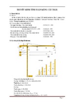
I. General
After first girder casting finished, through process of monitoring, we found that there are some cracks and breaking concrete at locations
as follows:
Location: 1. Crack at contiguous location of void and solid section;
2. Location: Crack at angle of contiguous location of void and solid section;
3. Location: Crack of angle on girder end;
4. Location: Traverse crack of girder end;
5. Location: Breaking angle of bottom of girder;
6. Location: Breaking of partition of girder.
Reasons:
During process of construction, cracks may be appear: because of Creation of formwork, sequence of disassemble formwork, cut PC
strands…. are not suitable which cause local stress in concrete of girder over allowable limitation, simultaneously some steel re-bars of girder
end is short of length comparing with technical design drawing.
Reference of some projects constructed (Ring Road No. 3) also happened situation as the above mentioned. After applied some solutions to
treat, it reached good result, therefore we would like to propose some solutions as follows:
Page 1 of 13
CIVIL ENGINEERING CONSTRUCTION CORPORATION No.4
PROJECT MANAGEMENT BOARD – NHAT TAN P-3
II. Countermeasure:
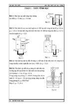
1. Location: Crack at contiguous location of void and solid section:
(See picture in Appendix 1)
+ Countermeasure: Add more 6 rebars A1-D12, L=1000 mm, @200mm at the connection between void and solid of the girder
Page 2 of 13
CIVIL ENGINEERING CONSTRUCTION CORPORATION No.4
PROJECT MANAGEMENT BOARD – NHAT TAN P-3
2. Location: Crack at angle of contiguous location of void and solid section:
(See picture in Appendix 2)
+ Countermeasure: Add a re-bar A2-D12, L=3421 mm and a re-bar A3-D12, L=2928 mm
Page 3 of 13
CIVIL ENGINEERING CONSTRUCTION CORPORATION No.4
PROJECT MANAGEMENT BOARD – NHAT TAN P-3
3. Location: Crack of angle on girder end
(See picture in Appendix 3)
+ Countermeasure: Add 2 re-bars A4-D12, L=720 mm and add 2 re-bars A5-D12, L=610 mm, @50 mm.
And cut 1.3m formwork of girder flange so that when cut cable we can disassemble formwork
Page 4 of 13
CIVIL ENGINEERING CONSTRUCTION CORPORATION No.4
PROJECT MANAGEMENT BOARD – NHAT TAN P-3
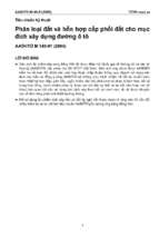
4. Location: Traverse crack of girder end
(See picture in Appendix 4)
+ Countermeasure: Extend bar NY10-D16 and bar NY11-D16 with length 1329 mm into length 1440 mm.
A
B
Page 5 of 13
CIVIL ENGINEERING CONSTRUCTION CORPORATION No.4
PROJECT MANAGEMENT BOARD – NHAT TAN P-3
5. Location: Breaking angle of bottom of girder
(See picture in Appendix 5)
+ Countermeasure:
- Cutting bottom formwork of girder end and change by rubber cushion (panel).
- Be careful during compacting concrete
6. Location: Breaking of partition of girder
(See picture in Appendix 6)
+ Countermeasure:
- Surface grinding of angle of internal formwork, cleaning carefully before installing
- When disassemble internal formwork, using 6 jacks to lift internal formwork up (replace the use 4 jacks as used on site) after that using gantry
crane to crane internal formwork out of.
Page 6 of 13
CIVIL ENGINEERING CONSTRUCTION CORPORATION No.4
PROJECT MANAGEMENT BOARD – NHAT TAN P-3
7. We propose change sequence to cut cable as follows:
- The procedure of cutting strands as follows: from strand No. 18→ 6→ 30→ 31→ 17→ 19→ 5→ 7→ 29→ 32→ 16→ 20→ 4→ 8 → 28→
33→ 15→ 21→ 27→ 34→ 14→ 22→ 38→ 39→ 26→ 35→ 13→ 23→ 37→ 40→ 25→ 36 → 12→ 24→ 41→42 → 3→ 9→ 2→10 → 1→11.
Page 7 of 13
CIVIL ENGINEERING CONSTRUCTION CORPORATION No.4
PROJECT MANAGEMENT BOARD – NHAT TAN P-3
Appendix 1
Crack at contiguous location of void and solid section
Page 8 of 13
CIVIL ENGINEERING CONSTRUCTION CORPORATION No.4
PROJECT MANAGEMENT BOARD – NHAT TAN P-3
Appendix 2
Crack at angle of contiguous location of void and solid section:
Page 9 of 13
CIVIL ENGINEERING CONSTRUCTION CORPORATION No.4
PROJECT MANAGEMENT BOARD – NHAT TAN P-3
Appendix 3
Crack of angle on top of girder end
Page 10 of 13
CIVIL ENGINEERING CONSTRUCTION CORPORATION No.4
PROJECT MANAGEMENT BOARD – NHAT TAN P-3
Appendix 4
Traverse crack of girder end
Page 11 of 13
CIVIL ENGINEERING CONSTRUCTION CORPORATION No.4
PROJECT MANAGEMENT BOARD – NHAT TAN P-3
Appendix 5
Breaking angle of bottom of girder
Page 12 of 13
CIVIL ENGINEERING CONSTRUCTION CORPORATION No.4
PROJECT MANAGEMENT BOARD – NHAT TAN P-3
Appendix 6
Breaking of partition of girder
Page 13 of 13
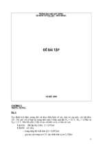
photographs of super t production
1
Contents:
2
Cleaning formwork, Installation of rebar and PC strand
3
Contents:
Contents:
4
Tensioning of PC strand
5
Installation of inner formwork and casting concrete
Pic No. 1 & 2
Pic No. 3 & 4
6
Pic No. 5 & 6
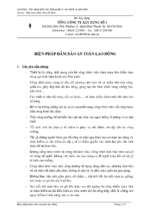
photographs of super t production
Contents:
Installation of inner formwork and casting concrete
7
Contents:
8
Checking temperature and slump of concrete
9
Contents:
Pic No. 5 & 6
Pic No. 7 & 8
10
Cutting of PC strand
11
Pic No. 9 & 10
12
Nhat Tan Bridge Construction Project
Contract Package 3
Tokyu Construction Co., Ltd
Report on casting figure, crack happen and Construction
countermeasure to prevent reoccurrence
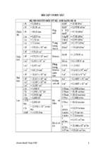
TABLE OF CONTENTS
1. General Description ......................................................................................................................... 2
2. Report of Casting Figure.................................................................................................................. 2
2.1
Location Map ..................................................................................................................... 2
2.2
Casting time ....................................................................................................................... 2
2.3
Casting sequence................................................................................................................ 2
2.4
Curing concrete.................................................................................................................. 2
2.5
Removal of inner formwork............................................................................................... 3
2.6
Compressive strength of concrete ................................................................................. … 4
3. Cutting PC strand and monitoring camber and cracks…………………………………………… . 4
4.
3.1
Cutting PC strand…………………………………………………………………………..4
3.2
Monitoring camber……………………………………………………………………… ..4
3.3
Monitoring cracks………………………………………………………………………….5
3.4
The reasons of incident……………………………………………………………………..6
Countermeasure to prevent reoccurence……………………………………………………… ... 11
4.1
Summary of crack locations………………………………………………………………. 11
4.2
Countermeasure………………………………………………………………………….…11
4.2.1 Crack at contiguous location of void and solid section (at girder web)………………..11
4.2.2 Crack at contiguous location of void and solid section (at girder wing)…………………13
4.2.3 Crack of angle on girder end (wing part)…………………………………………………14
4.2.4 Tranverse crack at girder end……………………………………………………………..16
4.2.5 Breaking at the bottom of girder end…………………………………………………..…17
4.2.6 Breaking of partition of girder…………………………………………………...……..18
5.
Changing of cutting sequence………………………………………………………………..... .18
6.
Appendix 1 ……………………………………………………………………………………….19
7.
Appendix 2 …………………………………………………………………………………….....21
8.
Appendix 3 …………………………………………………………………………………….....23
Total: 24 pages
1
Nhat Tan Bridge Construction Project
Contract Package 3
Tokyu Construction Co., Ltd
1
Report on casting figure, crack happen and Construction
countermeasure to prevent reoccurrence
General Description
This report describes actual casting figure of first super T girder of Thiep River bridge, mention the reasons of the
cracks happened after cutting PC strand and cranning girder out of formwork and propose the coutermeasure to
prevent re-occurrence.
2
Report of casting Figure
2.1 Location Map
Super T girder production for Thiep River Bridge was carried out at Vinh Ngoc Temporary Facilities
( appendix 1).
Girder No. G-1-12
2.2 Casting time :
Casting date
: 28th , May 2011
Casting duration
: 17h30’ to 22h27’
It toke 5 hours to finish casting concrete, this is unexpected time. The reasonable countermeasure shall be
propose to shorten the casting time.
( See Appendix 2 –Inspection sheet for placing concrete)
2.3 Casting sequence.
2.3.1. Supplying concrete.
Concrete grade : C50.
Design Slump : 15 ± 2.5 cm.
2.3.2. Work procedure.
Concrete was mixed at site Batching Plant ( 60m3/h) and delivered to casting yard by mixer truck.
Temperature and slump of concrete was checked prior to casting concrete to ensure the temperature is
always less than 32oC and the slump is 15 ± 2.5 cm.
Concrete was poured directly to girder formwork by concrete chute from mixer truck..
Detail ( Appendix 3).
2.4 Curing concrete.
Using wet jute sheet to cover on wing of girder after casting concrete 6 hours and supplying water to keep
the jute in wet condition.
Curing layout
2
Nhat Tan Bridge Construction Project
Contract Package 3
Tokyu Construction Co., Ltd
Report on casting figure, crack happen and Construction
countermeasure to prevent reoccurrence
H.1
2.5 Removal of inner formwork.
Inner formwork were removed on 30th May, 2011. Gantry crane was used to crane formwork out with
support of 04 hydraulic jacks.
H.2
2.6 Compressive strength of concrete
15 cylinder specimens were casted for 01st super T girder with the Engineer’s approval. 06 specimens
3
Nhat Tan Bridge Construction Project
Contract Package 3
Tokyu Construction Co., Ltd
Report on casting figure, crack happen and Construction
countermeasure to prevent reoccurrence
were cured on site at the same curing condition of girder, strength test shall be carried out at 03 and 04
days after casting and compressive strength of these specimens will be used to confirm the time for
cutting PC strand, remaining specimens were cured at site Laboratory, strength Test shall be carried out
at 07 and 28 days after casting.
Compressive strength at 03 days:
41.3 MPa ( average)
Compressive strength at 04 days:
43.8 Mpa ( average)
Compressive strength at 07 days:
54.45 Mpa ( average)
3. Cutting PC strand and monitoring camber and cracks.
3.1
Cutting PC Strand.
Cutting PC strand was carried out when compressive strength of concrete is not less than 42.5 Mpa
( 85% design strength).
Date of cutting : 02rd June, 2011.
Concrete strength at 04 days : 43.8 MPa.
PC strand were cut individually and simultaneously at two end of girder, cutiing procedure was shown as
below sketch.
H.3
3.2 Monitoring camber.
- Camber after cutting PC strand
: 34 mm
3.3 Monitoring cracks.
a) When removing inner formwork,
4
Nhat Tan Bridge Construction Project
Contract Package 3
Tokyu Construction Co., Ltd
Report on casting figure, crack happen and Construction
countermeasure to prevent reoccurrence
H4
b) After cutting PC strand and cranning girder out of formwork, there were some crack appear at the
end of girder.( see the sketch below).
H.5
c) After cutting PC strand and move girder to stock yard (after 03 days), there were some crack appear
at the end, the web and the wing of girder .( see the sketch below).
+ At girder web and wing:
5
- Xem thêm -