Chapter 1
Design for Flexure
By Murat Saatcioglu1
1.1 Introduction
Design of reinforced concrete elements for flexure involves; i) sectional design and ii) member
detailing. Sectional design includes the determination of cross-sectional geometry and the required
longitudinal reinforcement as per Chapter 10 of ACI 318-05. Member detailing includes the
determination of bar lengths, locations of cut-off points and detailing of reinforcement as governed by
the development, splice and anchorage length requirements specified in chapter 12 of ACI 318-05.
This Chapter of the Handbook deals with the sectional design of members for flexure on the basis of
the Strength Design Method of ACI 318-05. The Strength Design Method requires the conditions of
static equilibrium and strain compatibility across the depth of the section to be satisfied.
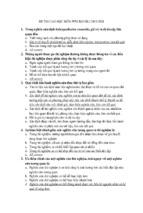
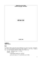
The following are the assumptions for Strength Design Method:
i. Strains in reinforcement and concrete are directly proportional to the distance from neutral axis.
This implies that the variation of strains across the section is linear, and unknown values can be
computed from the known values of strain through a linear relationship.
ii. Concrete sections are considered to have reached their flexural capacities when they develop
0.003 strain in the extreme compression fiber.
iii. Stress in reinforcement varies linearly with strain up to the specified yield strength. The stress
remains constant beyond this point as strains continue increasing. This implies that the strain
hardening of steel is ignored.
iv. Tensile strength of concrete is neglected.
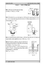
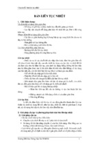
v. Compressive stress distribution of concrete can be represented by the corresponding stressstrain relationship of concrete. This stress distribution may be simplified by a rectangular stress
distribution as described in Fig. 1-1.
1
Professor and University Research Chair, Dept. of Civil Engineering, University of Ottawa, Ottawa, CANADA
1
β1 = 0.85
β1 = 0.85− 0.05
for f c ' ≤ 4000 psi
f c '−4000
≥ 0.65 for f 'c > 4000psi
1000
Fig. 1-1 Ultimate strain profile and corresponding rectangular stress distribution
1.2 Nominal and Design Flexural Strengths (Mn, and φMn)
Nominal moment capacity Mn of a section is computed from internal forces at ultimate strain profile
(when the extreme compressive fiber strain is equal to 0.003). Sections in flexure exhibit different
modes of failure depending on the strain level in the extreme tension reinforcement. Tensioncontrolled sections have strains either equal to or in excess of 0.005 (Section 10.3.4 of ACI 318-05).
Compression-controlled sections have strains equal to or less than the yield strain, which is equal to
0.002 for Grade 60 reinforcement (Section 10.3.3 of ACI 318-05). There exists a transition region
between the tension-controlled and compression-controlled sections (Section 10.3.4 of ACI 318-05).
Tension-controlled sections are desirable for their ductile behavior, which allows redistribution of
stresses and sufficient warning against an imminent failure. It is always a good practice to design
reinforced concrete elements to behave in a ductile manner, whenever possible. This can be ensured by
limiting the amount of reinforcement such that the tension reinforcement yields prior to concrete
crushing. Section 10.3.5 of ACI 318-05 limits the strain in extreme tension reinforcement to 0.004 or
greater. The amount of reinforcement corresponding to this level of strain defines the maximum
amount of tension reinforcement that balances compression concrete. The ACI Code requires a lower
strength reduction factor (φ-factor) for sections in the transition zone to allow for increased safety in
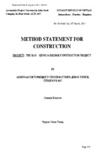
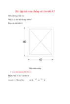
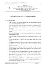
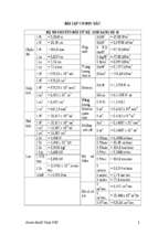
sections with reduced ductility. Figure 1-2 illustrates the variation of φ-factors with tensile strain in
reinforcement for Grade 60 steel, and the corresponding strain profiles at ultimate.
The ACI 318-05 Code has adopted strength reduction factors that are compatible with ASCE7-02 load
combinations, except for the tension controlled section for which the φ-factor is increased from 0.80 to
0.90. These φ-factors appear in Chapter 9 of ACI 318-05. The φ-factors used in earlier editions of ACI
318 and the corresponding load factors have been moved to Appendix C of ACI 318-05. The designer
has the option of using either the φ-factors in the main body of the Code (Chapter 9) or those given in
Appendix C, so long as φ-factors are used with the corresponding load factors. The basic design
inequality remains the same, irrespective of which pair of φ and load factors is used:
Factored (ultimate) moment ≤ Reduced (design) strength
Mu ≤ φMn
2
Appendix C
=0.57+67 t
0.003
=0.90
te
Reinforcement
closest to the
tension face
nc
o
i
ns
led
l
o
tr
tra
n
zo sitio
ne n
dt
on
t
=0.70
compression =0.65
controlled
= 0.002
t=0.004
Chapter 9
=0.48+83 t
t = 0.002
t = 0.005
minimum permitted
for beams
= 0.004 min. strain permitted
t
for pure flexure
t = 0.005
Fig. 1-2 Capacity reduction (φ) factors for Grade 60 reinforcement
1.2.1 Rectangular Sections with Tension Reinforcement
Nominal moment capacity of a rectangular section with tension reinforcement is computed from the
internal force couple shown in Fig. 1-1. The required amount of reinforcement is computed from the
equilibrium of forces. This computation becomes easier for code permitted sections where the tension
steel yields prior to the compression concrete reaching its assumed failure strain of 0.003. Design aids
Flexure 1 through Flexure 4 (included at the end of the chapter) were developed using this condition.
Accordingly;
T =C
As f y = 0.85f' c β1cb
ρ =
(1-2)
0.85 f ' c β 1 c
df y
(1-3)
As
bd
(1-4)
ρ=
where;
(1-1)
The c/d ratio in Eq. (1-3) can be written in terms of the steel strain εs illustrated in Fig. 1-1. For
sections with single layer of tension reinforcement, d = dt and εs = εt. The c/d ratio for this case
becomes;
c
c
0.003
=
=
d
dt
0.003 + ε t
(1-5)
0.85 f c ' β1 0.003
fy
0.003 + ε t
(1-6)
ρ=
3
Eq. (1-6) was used to generate the values for reinforcement ratio ρ (%) in Flexure 1 through Flexure 4
for sections with single layer of tension reinforcement. For other sections, where the centroid of
tension reinforcement does not necessarily coincide with the centroid of extreme tension layer, the ρ
values given in Flexure 1 through Flexure 4 should be multiplied by the ratio dt/d.
The nominal moment capacity is computed from the internal force couple as illustrated below:
M n = As f y (d −
From Eq. (1-2);
Where;
β1 c =
β1 c
)
2
As f y
0.85f' c b
(1-7)
(1-8)
ρ fy ⎤
⎡
M n = bd 2 ⎢1 −
⎥ρ fy
1.7f c ' ⎦
⎣
(1-9)
M n = bd 2 K n
(1-10)
ρ fy ⎤
⎡
K n = ⎢1 −
⎥ρ f y
1 .7 f c ' ⎦
⎣
(1-11)
Flexure 1 through Flexure 4 contains φKn values computed by Eq. (1-11), where the φ-factor is
obtained from Fig. 1-2 for selected values of εt listed in the design aids.
Design Examples 1 through 4 illustrate the application of Flexure 1 to Flexure 4.
1.2.2 Rectangular Sections with Compression Reinforcement
Flexural members are designed for tension reinforcement. Any additional moment capacity required in
the section is usually provided by increasing the section size or the amount of tension reinforcement.
However, the cross-sectional dimensions in some applications may be limited by architectural or
functional requirements, and the extra moment capacity may have to be provided by additional tension
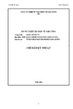
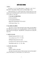
and compression reinforcement. The extra steel generates an internal force couple, adding to the
sectional moment capacity without changing the ductility of the section. In such cases, the total
moment capacity consists of two components; i) moment due to the tension reinforcement that
balances the compression concrete, and ii) moment generated by the internal steel force couple
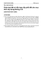
consisting of compression reinforcement and equal amount of additional tension reinforcement, as
illustrated in Fig. 1-3.
4
Fig. 1-3 A rectangular section with compression reinforcement
M n = M1 + M 2
(1-12)
M 1 = K n bd 2
(1-13)
M 2 = As ' f ' s (d − d ' )
(1-14)
M 2 = Kn 'b d 2
(1-15)
Assuming f’s is equal to or greater than fy;
where;
and
K n ' = ρ' f y ( 1 −
ρ'=
d'
)
d
As '
bd
(1-16)
(1-17)
Since the steel couple does not involve a force in concrete, it does not affect the ductility of the section,
i.e., adding more tension steel over and above the maximum permitted by the Code does not create an
over-reinforced section, and is permissible by ACI 318-05 so long as an equal amount is placed in the
compression zone. This approach is employed for design, as well as in generating Flexure 5, which
provides the amount of compression reinforcement. The underlining assumption in computing the steel
force couple is that the steel in compression is at or near yield, developing compressive stress equal to
the tensile yield strength. While this assumption is true in most heavily reinforced sections since the
compression reinforcement is near the extreme compression fiber with a strain of 0.003, especially for
Grade 60 steel with 0.002 yield strain, it is possible to design sections with non-yielding compression
reinforcement. The designer, in this case, has to adjust (increase) the amount of compression
reinforcement in proportion to the ratio of yield strength to compression steel stress. The strain in
compression steel ε’s can be computed from Fig. 1-3 as ε’s = εs (c-d’)/(d-d’), once εs is determined
from flexural design tables for sections with tension reinforcement (Flexure 1 through Flexure 4) to
assess if the compression steel is yielding.
The application of Flexure 5 is illustrated in Design Example 5.
5
1.2.3 T-Sections
Most concrete slabs are cast monolithically with supporting beams, with portions of the slab
participating in flexural resistance of the beams. The resulting one-way structural system has a Tsection. The flange of a T-section is formed by the effective width of the slab, as defined in Section
8.10 of ACI 318-05, and also illustrated in Flexure 6. The rectangular beam forms the web of the Tsection. T-sections may also be produced by the precast industry as single and double T’s because of
their superior performance in positive moment regions. A T-section provides increased area of
compression concrete in the flange, where it is needed under positive bending, with reduced dead load
resulting from the reduced area of tension concrete in the web.
The flange width in most T-sections is significantly wider than the web width. Therefore, the amount
of tension reinforcement placed in the web can easily be equilibrated by a portion of the flange
concrete in compression, placing the neutral axis in the flange. Therefore, most T-sections behave as
rectangular sections, even though they have T geometry, and are designed using Flexure 1 through
Flexure 4 as rectangular sections with section widths equal to flange widths.
Rarely, the required amount of tension reinforcement in the web (or the applied moment) is high
enough to bring the neutral axis below the flange, creating an additional compression zone in the web.
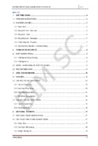
In such a case, the section behaves as a T-section with total moment capacity consisting of components
due to; i) compression concrete in the overhangs (b-bw) and a portion of total tension steel balancing
the overhangs, ρf and ii) the remaining tension steel, ρw balancing the web concrete. The condition for
T-section behavior is expressed below:
M u > φ [0.85 f c ' bh f (d −
hf
2
)]
(1-18)
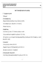
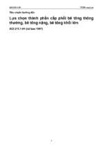
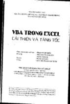
The components of moment for T-section behavior are illustrated in Fig. 1-4, and are expressed below.
b
d
As
hf
=
bw
Cf
+
Mnf
Asf
bw
Tf
n.a.
Asw
Cw
Mnw
Tw
Fig. 1-4 T-section behavior
M n = M nf + M nw
(1-19)
M nf = K nf (b − bw )d 2
(1-20)
M nw = K nwbw d 2
(1-21)
6
ρf =
and;
ρw =
Asf
(b − bw )d
Asw
bw d
(1-22)
(123)
Moment components, Mnf and Mnw can be obtained from Flexure 1 though Flexure 4 when the tables
are entered with ρf and ρw values, respectively. For design, however, ρf needs to be found first and this
can be done from the equilibrium of internal forces for the portion of total tension steel balancing the
overhang concrete. This is illustrated below.
Tf = C f
Asf f y = 0.85 f c ' h f ( b − bw )
ρf =
0.85 f c ' h f
fy
d
(1-24)
(1-25)
(1-26)
Eq. (1-26) was used to generate Flexure 7 and Flexure 8. Flexure Example 6 through Flexure
Example 8 illustrate the use of Flexure 7 and Flexure 8.
When T-beam flanges are in tension, part of the flexural tension reinforcement is required to be
distributed over an effective area as illustrated in Flexure 6 or a width equal to one-tenth the span,
whichever is smaller (Sec. 10.6.6). This requirement is intended to control cracking that may result
from widely spaced reinforcement. If one-tenth of the span is smaller than the effective width,
additional reinforcement shall be provided in the outer portions of the flange to minimize wide cracks
in these regions.
1.3 Minimum Flexural Reinforcement
Reinforced concrete sections that are larger than required for strength, for architectural and other
functional reasons, may need to be protected by minimum amount of tension reinforcement against a
brittle failure immediately after cracking. Reinforcement in a section becomes effective only after the
cracking of concrete. However, if the area of reinforcement is too small to generate a sectional capacity
that is less than the cracking moment, the section can not sustain its strength upon cracking. To
safeguard against such brittle failures, ACI 318 requires a minimum area of tension reinforcement both
in positive and negative moment regions (Sec. 10.5.1).
As ,min =
3 fc '
bw d ≥ 200bw d / f y
(1-27)
fy
The above requirement is indicated in Flexure 1 through Flexure 4 by a horizontal line above which
the reinforcement ratio ρ is less than that for minimum reinforcement.
7
When the flange of a T-section is in tension, the minimum reinforcement required to have a sectional
capacity that is above the cracking moment is approximately twice that required for rectangular
sections. Therefore, Eq. (1-27) is used with bw replaced by 2bw or the width of the flange, whichever is
smaller (Sec. 10.5.2). If the area of steel provided in every section of a member is high enough to
provide at least one-third greater flexural capacity than required by analysis, then the minimum steel
requirement need not apply (Sec. 10.5.3). This exception prevents the use of excessive reinforcement
in very large members that have sufficient reinforcement.
For structural slabs and footings, minimum reinforcement is used for shrinkage and temperaturecontrol (Sec. 10.5.4). The minimum area of such reinforcement is 0.0018 times the gross area of
concrete for Grade 60 deformed bars (Sec. 7.12.2.1). Where higher grade reinforcement is used, with
yield stress measured at 0.35% strain, the minimum reinforcement ratio is proportionately adjusted as
(0.0018 x 60,000)/fy. The maximum spacing of shrinkage and temperature reinforcement is limited to
three times the slab or footing thickness or 18 in, whichever is smaller (Sec. 10.5.4).
1.4 Placement of Reinforcement in Sections
Flexural reinforcement is placed in a section with due considerations given to the spacing of
reinforcement, crack control and concrete cover. It is usually preferable to use sufficient number of
small size bars, as opposed to fewer bars of larger size, while also respecting the spacing requirements.
1.4.1 Minimum Spacing of Longitudinal Reinforcement
Longitudinal reinforcement should be placed with sufficient spacing to allow proper placement of
concrete. The minimum spacing requirement for beam reinforcement is shown in Flexure 9.
1.4.2 Concrete Protection for Reinforcement
Flexural reinforcement should be placed to maximize the lever arm between internal forces for
increased moment capacity. This implies that the main longitudinal reinforcement should be placed as
close to the concrete surface as possible. However, the reinforcement should be protected against
corrosion and other aggressive environments by a sufficiently thick concrete cover (Sec. 7.7), as
indicated in Flexure 9. The cover concrete should also satisfy the requirements for fire protection (Sec.
7.7.7).
1.4.3 Maximum Spacing of Flexural Reinforcement and Crack Control
Beams reinforced with few large size bars may experience cracking between the bars, even if the
required area of tension reinforcement is provided and the sectional capacity is achieved. Crack widths
in these members may exceed what is usually regarded as acceptable limits of cracking for various
exposure conditions. ACI 318-05 specifies a maximum spacing limit “s” for reinforcement closest to
the tension face. This limit is specified in Eq. (1-28) to ensure proper crack control.
⎛ 40 ,000 ⎞
⎛ 40 ,000 ⎞
⎟⎟ − 2.5cc ≤ 12⎜⎜
⎟⎟
s = 15⎜⎜
⎝ fs ⎠
⎝ fs ⎠
(1-28)
8
where; cc is the least distance from the surface of reinforcement to the tension face of concrete, and fs
is the service load stress in reinforcement. fs can be computed from strain compatibility analysis under
unfactored service loads. In lieu of this analysis, fs may be taken as 2/3 fy. Eq. (1-28) does not provide
sufficient crack control for members subject to very aggressive exposure conditions or designed to be
watertight. For such structures, special investigation is required (Sec. 10.6.5).
The maximum spacing of flexural reinforcement for one-way slabs and footings is limited to three
times the slab or footing thickness or 18 in, whichever is smaller (Sec. 10.5.4).
1.4.4 Skin Reinforcement
In deep flexural members, the crack control provided by the above expression may not be sufficient to
control cracking near the mid-depth of the section, between the neutral axis and the tension concrete.
For members with a depth h > 36 in, skin reinforcement with a maximum spacing of s, as defined in
Eq. (1-28) and illustrated in Flexure 10 is needed (Sec. 10.6.7). In this case, cc is the least distance
from the surface of the skin reinforcement to the side face. ACI 318 does not specify the area of steel
required as skin reinforcement. However, research has indicated that bar sizes of No. 3 to No. 5 or
welded wire reinforcement with a minimum area of 0.1 square inches per foot of depth provide
sufficient crack control2.
2
Frosch, R.J., “Modeling and Control of Side Face Beam Cracking,” ACI Structural Journal, V. 99, No.3, May-June 2002,
pp. 376-385.
9
1.5 Flexure Examples
FLEXURE EXAMPLE 1 -
Calculation of area of tension reinforcement for a rectangular tension
controlled cross-section.
For a rectangular section subjected to a factored bending moment Mu, determine the required area of tension
reinforcement for the dimensions given. Assume interior construction not exposed to weather.
b
Given:
Mu = 90 kip-ft
fc' = 4,000 psi
fy = 60,000 psi
b = 10 in
h = 20 in
d
h
As
Procedure
Calculation
Estimate "d" by allowing for clear cover,
the radius of longitudinal reinforcement
and diameter of stirrups.
Considering a minimum clear cover of 1.5
inches for interior exposure, allow 2.50 in
to the centroid of main reinforcement
d = 20 - 2.50 = 17.50 in
φKn = 90x12,000/[10x(17.50)2] = 353 psi
For φKn = 353 psi; ρ = 0.70%
Compute φKn = Mu x 12,000 / (bd2)
Select ρ from Flexure 1
Compute required area of steel; As = ρbd
Determine the provided area of steel
(For placement of reinforcement see
Flexure Example 9)
As = ρbd = 0.0070x10x17.5 = 1.22 in2
Use 3 #6 (As)prov. = (3)(0.44) = 1.32 in2
(Note: 3 # 6 can be placed within a 10 in.
width).
(ρ)prov = (1.32)/[(10)(17.5)] = 0.75%
Note: for (ρ)prov = 0.75%; εt = 0.0163
εt = 0.0163 > 0.005 “tension controlled”
section and φ = 0.9.
FLEXURE EXAMPLE 2 -
ACI
318-05
Section
Design
Aid
7.7.1
Flexure 9
Flexure 1
7.6.1
3.3.2
Flexure 9
10.3.4
9.3.2
Flexure 1
Calculation of nominal flexural capacity of a rectangular beam subjected
to positive bending.
For a rectangular section with specified tension reinforcement and geometry determine the nominal flexural
capacity Mn.
Given:
3 #6 Bars as bottom tension reinforcement
fc' = 4,000 psi
fy = 60,000 psi
b = 10 in
d = 18 in
b
d
h
As
10
Procedure
Calculation
Compute the area and percentage of steel
provided
Select φKn from Flexure 1
Compute φMn = φKn bd2 /12,000
Select corresponding φ from Flexure 1
As = 3 x 0.44 = 1.32 in2
ρ = As/bd = 1.32/(10)(18) = 0.73%
For ρ = 0.73%; φKn = 370 psi
φMn = 370 x 10 x (18)2 / 12,000 = 100 k-ft
φ = 0.9
(εt =0.01675 > 0.005 “tension controlled”)
Mn = 100/0.9 = 111 k-ft
Compute Mn = φMn /φ
FLEXURE EXAMPLE 3 -
ACI 318
2005
Section
Design
Aid
Flexure 1
10.3.4
9.3.2
Flexure 1
Calculation of area of tension reinforcement for a rectangular cross section
in the transition zone.
For a rectangular section subjected to a factored bending moment Mu, determine the required area of tension
reinforcement for the dimensions given. Assume interior construction not exposed to weather.
b
Given:
Mu = 487 kip-ft
fc' = 4,000 psi
fy = 60,000 psi
b = 14 in
h = 26 in
1.0 in. maximum aggregate size
d
h
As
Procedure
Calculation
Estimate "d" by allowing for clear cover,
the radius of longitudinal reinforcement
and diameter of stirrups.
Compute φKn = Mu x 12,000 / (bd2)
Select ρ from Flexure 1
Considering a minimum clear cover of 1.5
in for interior exposure, allow 2.50 in. to
the centroid of main reinforcement
d = 26 - 2.50 = 23.50 in
φKn = 487x12,000/[14x(23.50)2] = 756 psi
For φKn = 756 psi; ρ = 1.63%
Compute As = ρbd
As = ρbd = 0.0163x14 x 23.5 = 5.36 in2
Determine the area of steel provided
Try #8 bars; 5.36 /0.79 = 6.8
Need 7 #8 bars in a single layer. However
7 #8 bars can not be placed in a single
layer within a 14 in. width without
violating the spacing limits. Therefore, try
placing them in double layers.
ACI 318
2005
Section
Design
Aid
7.7.1
Flexure 9
Flexure 1
7.6.1
3.3.2
Flexure 9
Allow 3.5 in. from the extreme tension
fiber to the centroid of double layers of
reinforcement.
Revise d = 26 – 3.5 = 22.5 in.
11
φKn = 487x12,000/[14x(22.50)2] = 825 psi
For φKn = 825 psi; ρ = 1.98%
As = ρbd = 0.0198x14 x 22.5 = 6.24 in2
Flexure 1
Try #8 bars; 6.24 /0.79 = 7.9
Select 8 #8 bars in two layers (4 # 8 in
each layer). Note that 4 #8 bars can be
placed within a 14 in. width.
(As)prov.= (8) (0.79) = 6.32 in2
(ρ)prov. = 6.32 / [(14)(22.5)] = 0.020
For (ρ)prov. = 0.020 φKn = 826 psi
εt = 0.0042
Note: εt = 0.0042 < 0.005 “transition
zone”; φ = 0.83 and φKn > Mu
FLEXURE EXAMPLE 4 -
7.6.1
3.3.2
Flexure 9
Flexure 1
10.3.4
9.3.2
Flexure 1
Selection of slab thickness and area of flexural reinforcement.
For a slab subject to a factored bending moment Mu, determine the thickness h and required area of tension
reinforcement. The slab has interior exposure.
12 in
Given:
Mu = 11 kip-ft/ft
fc' = 4,000 psi
fy = 60,000 psi
Procedure
d
Calculation
ρ = 0.5(ρ at εt =0.005)
= 0.5 x 0.018 = 0.0091
for ρ = 0.0091; φKn = 453 psi
φKn = Mu x 12,000 / (bd2)
d2 = Mu x 12,000/(φKn b)
d2 = 11 x 12,000/(453 x 12) = 24.3 in2
d = 5.0 in
Select bar size and cover concrete.
As = ρbd = 0.0091 (12) (5.0) = 0.55 in2
(For reinforcement placement see
#5 at 6 in. provides As = 0.62 in.2 O.K.
Flexure Example 10).
Cover = 0.75 in
h = d + db/2 + cover = 5.0 + 0.625/2 + 0.75
Compute h with due considerations
given to cover and bar radius.
h = 6.1 in
Use h = 6.5 in
Note that the slab thickness must also
Note: The slab thickness should be
satisfy deflection control.
checked to satisfy the requirements of
(For placement of reinforcement see Table 9.5(a) for deflection control.
Flexure Example 10)
h
ACI 318
2005
Section
Unless a certain slab thickness is desired,
a trial thickness can be selected such that
a section with good ductility, stiffness
and bar placement characteristics is
obtained. Try ρ = 50% of ρ at max. limit
of tension controlled section.
Design
Aid
Flexure 1
7.7.1
9.5.2 and
Table
9.5(a)
12
FLEXURE EXAMPLE 5 -
Calculation of tension and compression reinforcement area for a
rectangular beam section, subjected to positive bending.
For a rectangular section subjected to a factored positive moment Mu, determine the required area of tension and
compression reinforcement for the dimensions given below.
Given:
Mu = 580 kip-ft
fc' = 4,000 psi
fy = 60,000 psi
b = 14 in
h = 24 in
d’ = 2.5 in
b
d
As'
As
Procedure
Calculation
Estimate "d" by allowing for clear cover,
the radius of longitudinal reinforcement
and diameter of stirrups.
Considering a minimum clear cover of 1.5
in for interior exposure, allow 2.5 in. to the
centroid of main reinforcement.
d = 24 - 2.5 = 21.5 in
φKn = 580x12,000/[14x(21.5)2] =1075 psi
φKn = 1075 psi is outside the range of
Flexure 1. This indicates that the amount
of steel needed exceeds the maximum
allowed if only tension steel were to be
provided. Therefore, compression steel is
needed.
Select; ρ = 0.018 (εt = 0.005)
As-As’= ρbd = 0.018 x 14 x 21.5
= 5.42 in2
Try #8 bars; 5.42 / 0.79 = 6.9
Select 7 #8 bars for As-As’
However, 7 # 8 can not be placed in a
single layer. Try using double layers.
Compute φKn = Mu x 12,000 / (bd2)
Select ρ from Flexure 1
Compute (As-As’)
In this problem select a reinforcement
ratio close to the maximum allowed to
take advantage of the full capacity of
compression concrete. Select ρ = 1.80 %
(slightly below ρmax = 2.06% so that
when the actual bars are placed ρmax is
not exceeded).
Compute moment to be resisted by
d'
ACI 318
2005
Section
7.7.1
Design
Aid
Flexure 9
Flexure 1
Flexure 1
7.6.1
3.3.2
Flexure 9
Allow 3.5 in. from the extreme tension
fiber to the centroid of double layers of # 8
bars.
Revise d = 24 – 3.5 = 20.5 in
As-As’= ρbd = 0.018 x 14 x 20.5
= 5.17 in2
Try #8 bars; 5.17 / 0.79 = 6.5
Select 7 #8 bars for (As-A’s) to be placed
in double layers. As-As’ = (7)(0.79)
= 5.53 in.2
Corresponding ρ = 5.53/[(14)(20.5)]
= 0.019 < ρmax = 0.0206 O.K.
For ρ = 0.019 φΚn = 823 psi; εt = 0.0046
10.3.4
9.3.2
Flexure 1
13
compression concrete and corresponding
tension steel (As-As’).
Compute moment to be resisted by the
steel couple (with an equal tension and
compression steel area of As’)
Compute As’
Note: As’ is determined from Flexure 5,
which was developed based on the
assumption that at ultimate the
compression steel is at or near yield. The
strain diagram shown indicates the
yielding of compression steel (f’s = f’y).
and φ = 0.87
φMn = φKn b d2 /12000
φMn = 823x14 (20.5)2 / 12,000 = 404 k-ft
φMn’ = Mu - φMn
φMn' = 580 - 404 = 176 k-ft
φKn’ = φMn’ x 12,000 / (bd2)
φKn’= 176x12,000 /[14 x (20.5)2] = 359 psi
Kn’ = 359/0.87 = 413 psi
d’/d = 2.5/20.5 = 0.12; ρ’ = 0.78%
As’ = ρ’ bd = 0.0078 x 14 x 20.5 = 2.24 in2
Flexure 5
If the compression steel does not yield
(f’s < f’y) then the area of compression
steel used should be reduced by f’s/f’y.
Determine the area of compression steel
provided.
Add equal area of steel to the bottom
bars to facilitate steel force couple.
Determine the total area of bottom
reinforcement, As
FLEXURE EXAMPLE 6 -
Use 3 #8 bars as compression
reinforcement. (As’)prov. = (3)(0.79)
= 2.37 in2
Add 3 #8 bars to the bottom reinforcement.
Total bottom reinforcement:
7 #8 + 3 # 8 = 10 # 8 to be provided in
double layers (5 #8 in each layer).
5 #8 can be placed within a width of 14 in.
As = 5.53 + 2.37 = 7.90 in2
Note: For this section:
εt = 0.00460 and φ = 0.87
7.6.1
3.3.2
Flexure 9
Calculation of tension reinforcement area for a T beam section subjected
to positive bending, behaving as a rectangular section.
For a T section subjected to a factored bending moment Mu, determine the required area of tension
reinforcement for the dimensions given.
b = 30"
Given:
Mu = 230 kip-ft
fc' = 4,000 psi
fy = 60,000 psi
b = 30 in
bw = 14 in
d = 19 in
hf = 2.5 in
hf = 2.5"
d = 19"
As
bw = 14"
14
ACI 318
2005
Section
Procedure
Calculation
Assume tension controlled section
(φ = 0.9). Determine if the section
behaves as a T or a rectangular section.
If Mu > φ[0.85f’c b hf (d-hf/2)] T-section,
otherwise rectangular section behavior.
0.9 [0.85f’cb hf (d - hf /2)]
= 0.9[0.85(4)(30)(2.5)(19-2.5/2)]
= 4073 k-in
= 340 k-ft > Mu = 230 k-ft Therefore, the
neutral axis is within the flange and the
section behaves as a rectangular section
with width b = 30 in.
φKn = (230)(12,000)/[(30)(19)2] = 255 psi
For φKn = 255 psi; ρ = 0.50 %
As = ρbd = 0.0050x30x19 = 2.85 in2
Compute φKn = Mu x 12,000 / (bd2)
Select ρ from Flexure 1
Compute As = ρbd
Use 5 #7 with As = (5)(0.6) = 3.00 in2
ρ = 3.00 / [(30)(19)] = 0.0053
For ρ = 0.0053; εt = 0.025 > 0.005
“tension controlled” section and φ = 0.9
Find provided area of steel.
Read εt and φ from Flexure 1.
FLEXURE EXAMPLE 7 -
Design
Aid
Flexure 1
10.3.4
9.3.2
Flexure 1
Computation of the area of tension reinforcement for a T beam section,
subjected to positive bending, behaving as a tension controlled T-section.
For a T section subjected to a factored bending moment Mu, determine the required area of tension
reinforcement for the dimensions given. The beam has interior exposure.
Given:
Mu= 400 kip-ft
fc' = 4,000 psi
fy = 60,000 psi
b = 30 in
bw =15 in
h = 24 in
hf = 2.5 in
Max. aggregate size = 1.0 in.
b =30"
h f = 2.5 "
h = 24"
As
bw =15 "
Procedure
Calculation
Estimate "d" by allowing for clear cover,
the radius of longitudinal reinforcement
and diameter of stirrups.
Considering a minimum clear cover of 1.5
in. for interior exposure, allow 2.5 in. to
the centroid of longitudinal reinforcement.
d = 24 - 2.5 = 21.5 in
0.9 [0.85f’cb hf (d - hf /2)]
= 0.9(0.85)(4)(30)(2.5)(21.5-2.5/2)
= 4647 k-in
= 387 k-ft < Mu = 400 k-ft Therefore, the
neutral axis is below the flange and the
section behaves as a T section.
Assume tension controlled section and
determine if the section behaves as a T
section or a rectangular section.
If Mu > φ[0.85f’c b hf (d-hf/2)] T-section,
otherwise rectangular section behavior.
ACI 318
2005
Section
7.7.1
Design
Aid
Flexure 9
15
Compute the amount of steel that
balances compression concrete in flange
overhangs from Flexure 7.
Find the amount of moment resisted by
ρf from Flexure 1.
Determine the amount of steel needed to
resist the remaining moment, that is to
be resisted by the web; ρw
Compute the total area of tension
reinforcement
Note: The φ factor can be computed
using the reinforcement ratio that
balances web concrete.
FLEXURE EXAMPLE 8 -
d/hf = 21.5/2.5 = 8.6
ρf = 0.66%
Flexure 7
For ρf = 0.66% φKn = 334 psi and φ = 0.9
φMf = φKn (b-bw)d2/12,000
= 334(30 – 15)(21.5)2/12,000 = 193 k-ft
φMw = Mu - φMf = 400 – 193 = 207 k-ft
φKn = φMw x 12,000 / [(bw)(d)2] = 358 psi
for φKn = 358 psi; ρw = 0.71%
Af = ρf (b-bw)d = 0.0066(30-15)(21.5)
= 2.13 in2
Aw = ρw bwd= 0.0071(15)(21.5) = 2.29 in2
As = Af + Aw = 2.13 + 2.29 = 4.42 in2
Flexure 1
Flexure 1
Try using # 9 bars; 4.42/1.00 = 4.42
Use 5 #9 bars in a single layer
(As)prov. = (5)(1.0) = 5.00 in2
7.6.1
3.3.2
Flexure 9
Provided area of steel that balances web
concrete: 5.00 – 2.13 = 2.87 in2
(ρw)prov. = 2.87/(15)(21.5) = 0.0089
This corresponds to εt = 0.0132 and φ = 0.9
(tension controlled section)
10.3.4
9.3.2
Flexure 1
Calculation of the area of tension reinforcement for an L beam section,
subjected to positive bending, behaving as an L-section in the transition
zone.
For an L section subjected to a factored bending moment Mu, determine the required area of tension
reinforcement for the dimensions given. The beam has interior exposure.
Given:
Mu = 1800 kip-ft
fc' = 4,000 psi
fy = 60,000 psi
b = 36 in
bw = 20 in
h = 36 in
hf = 3.0 in
Max. aggregate size = 3/4 in.
b = 36"
h f = 3.0"
h =36"
As
bw = 20"
Procedure
Calculation
ACI 318
2005
Section
Estimate "d" by allowing for clear cover,
diameter of stirrups and the radius of
longitudinal reinforcement.
Considering a minimum clear cover of 1.5
in. for interior exposure, allow 2.5 in. to
the centroid of main reinforcement.
d = 36 - 2.5 = 33.5 in
7.7.1
Design
Aid
Flexure 9
16
Assume tension controlled section and
determine if the section behaves as a Tsection (in this case as an L-section) or a
rectangular section.
If Mu > φ [0.85f’c b hf (d-hf/2)] T-section
otherwise rectangular section behavior.
Compute the amount of steel that
balances compression concrete in the
flange overhang, from Flexure 7
Find the amount of moment resisted by
ρf from Flexure 1.
Determine the amount of steel required
to resist the remaining moment. This
additional moment is to be resisted by
the web; ρw
Compute the total area of tension
reinforcement.
Recalculate the effective depth “d” and
revise design. Assume cover of 3.5 in. to
the centroid of double layers of
reinforcement.
Compute the amount of steel that
balances compression concrete in the
flange overhang, from Flexure 7
Find the amount of moment resisted by
ρf from Flexure 1.
Determine the amount of steel required
to resist the remaining moment. This
additional moment is to be resisted by
the web; ρw
Compute the total area of tension
reinforcement required.
0.9 (0.85)f’cb hf (d - hf /2)
= 0.9(0.85)(4)(36)(3.0)(33.5-3.0/2)
= 10,575 k-in
= 881 k-ft < Mu = 1800 k-ft Therefore,
the neutral axis is below the flange and the
section behaves as a T section.
d/hf = 33.5/3.0 = 11.2
ρf = 0.51 %
For ρf = 0.51 % φKn = 261 psi (φ = 0.90)
φMf = φKn (b-bw)d2/12,000
= 261 (36 – 20)(33.5)2/12,000 = 391 k-ft
φMw = Mu - φMf = 1800 – 391 = 1409 k-ft
φKn = φMw x 12,000 / [(bw)(d)2]
φKn = 1409x12,000/[(20)(33.5)2] = 753 psi
for φKn = 753 psi; ρw = 1.63 %
Note: φ = 0.90 (tension controlled).
Af = ρf (b-bw)d = 0.0051(36-20)(33.5)
= 2.73 in2
Aw = ρw bwd= 0.0163(20)(33.5) =10.92 in2
As = Af + Aw = 2.73 + 10.92 = 13.65 in2
Select #9 bars; 14 - #9 bars are needed.
14 - #9 bars can not be placed in a single
layer. Therefore, use double layers of
reinforcement and revise the design.
d = 36 – 3.5 = 32.5 in.
Note: Reduced “d” will result in increased
area of steel and the beam will continue
behaving as a T-Beam (no need to check
again).
d/hf = 32.5/3.0 = 10.8
ρf = 0.53 %
For ρf = 0.53 % φKn = 271 psi (φ = 0.90)
φMf = φKn (b-bw)d2/12,000
= 271 (36 – 20)(32.5)2/12,000 = 382 k-ft
φMw = Mu - φMf = 1800 – 382 = 1418 k-ft
φKn = φMw x 12,000 / [(bw)(d)2]
φKn = 1418x12,000/[(20)(32.5)2] = 806psi
for φKn = 806 psi; ρw = 1.77 %
Note: φ = 0.90.
Af = ρf (b-bw)d = 0.0053(36-20)(32.5)
= 2.76 in2
Aw = ρw bwd= 0.0177(20)(32.5) =11.51 in2
As = Af + Aw = 2.76 + 11.51 = 14.27 in2
Use 16 #9 bars in two layers (8 #9 in each
layer, which can be placed within 20 in.
width.
Flexure 7
Flexure 1
Flexure 1
7.6.1
3.3.2
Flexure 9
Flexure 7
Flexure 1
Flexure 1
7.6.1
3.3.2
Flexure 9
17
Ensure φMn ≥ Mu based on provided
reinforcement.
Aw = As – Af = 16.0 – 2.76 = 13.24 in2
Provided ρw that balances web concrete;
ρw = 13.24 / [(20)(32.5)] = 0.0204 = 2.04%
For ρw = 2.04 %; φKn = 827 and φ = 0.82
φMw = φ Kn bwd2 / 12,000
= (827)(20)(32.5)2 /12,000 =1456 k-ft
For the contribution of flange overhang
(0.90)Kn = 271 psi (found earlier)
(0.82)Kn = 271 (0.82/0.90) = 247 psi
φMf = φKn (b-bw)d2/12,000
φMf =(247)(36–20)(32.5)2 /12,000=348k-ft
Flexure 1
φMn = φMw + φMf =1456+ 348=1804 k-ft
φMn = 1804 k-ft > Mu = 1800 k-ft O.K.
FLEXURE EXAMPLE 9 -
Placement of reinforcement in the rectangular beam section designed in
Flexure Example 1.
Select and place flexural beam reinforcement in the section provided below, with due considerations given to
spacing and cover requirements.
b
Given:
As = 1.22 in2
b = 10 in
h = 20 in
fy = 60,000 psi
#3 stirrups
Max. aggregate size: 3/4 in
Interior exposure
d
h
As
Procedure
Calculation
Determine bar size and number of bars.
Select # 6 bars; No. of bars = 1.22/0.44 =
2.8
Use 3 # 6 bars
Considering minimum clear cover of 1.5
inches on each side for interior exposure
and allowing 2 stirrup bar diameters;
s = [10 – 2(1.5) – 2(0.375) – 3(0.75)]/ 2 =
2.0 in
1
(s)min = {db; 1 amax; 1 in}
3
1
(s)min = {0.75 in; 1 (3/4 in); 1 in} = 0.75 in
3
s = 2.0 in > 0.75 in O.K.
⎛ 40,000 ⎞
⎛ 40,000 ⎞
⎟⎟ − 2.5c c ≤ 12 ⎜⎜
⎟⎟
(s) maz = 15 ⎜⎜
⎝ fs ⎠
⎝ fs ⎠
fs = 2/3fy = 2/3 (60,000) = 40,000 psi
Determine bar spacing.
Check against minimum spacing
Check against maximum spacing as
governed by crack control
ACI
318-05
Section
Design
Aid
Appendix
A
7.7.1
Flexure 9
Appendix
A
7.6
Flexure 9
10.6.4
Eq.(1-28)
18
cc = (1.5 + 0.375) = 1.875 in
(s)max = 15 (1.0) – 2.5 (1.875) = 10.3 in
s = 2.0 in < 12 in O.K.
Provide 3 # 6 as indicated below.
Final bar placement
FLEXURE EXAMPLE 10 -
Flexure 9
Placement of reinforcement in the slab section designed in Example 4.
Select and place reinforcement in the 6 in slab shown below.
Given:
As = 0.62 in2/ft
fy = 60,000 psi
d = 5 in
h = 6.5 in
Procedure
12 in
d
Calculation
Determine bar size and number of bars
for a one-foot slab width.
Select # 5 bars; No. of bars = 0.62/0.31= 2
Use 2 # 5 bars per foot of slab width.
Check for minimum area of
reinforcement needed for temperature
and shrinkage control. Note that the
same minimum reinforcement must also
be provided in the transverse direction.
Check for maximum spacing of
reinforcement.
For Grade 60 steel As,min = 0.0018 Ag
As,min = 0.0018 (6.0)(12.0) = 0.13 in2
As = 2 x 0.31 = 0.62 > 0.13 O.K.
2 # 5 bars per foot results in s = 6 in
(s)max = 3h or 18 in, whichever is smaller
(s)max = 3(6) = 18 in
s = 6 in < 18 in O.K.
Final reinforcement placement
h
ACI 318
2005
Section
Design
Aid
Appendix
A
7.12.2.1
10.5.4
7.7.1
Flexure 9
Note clear cover = (6.5 – 5) – 0.625/2
= 1.2 in > ¾ in O.K.
19
1.6 Flexure Design Aids
Flexure 1 - Flexural coefficients for rectangular beams
b
0.003 0.85f'c
β1c
c
n.a.
with tension reinforcement, fy = 60,000 psi
φMn ≥ Mu
φMn = φKn b d2 /12000
ρ = As / b d
d
fy = 60000
fc' (psi) :
εt
As
where, Mn is in kip-ft; Kn is in psi; b and d are in inches
Cc
T
psi
3000
4000
5000
6000
β1 :
0.85
0.85
0.80
0.75
ρmin :
0.0033
0.0033
0.0035
0.0039
εt
φ
φApp C
ρ(%)
φKn (psi)
ρ(%)
φKn (psi)
ρ(%)
φKn (psi)
ρ(%)
φKn (psi)
0.20000
0.90
0.90
0.05
29
0.07
38
0.08
45
0.09
51
0.15000
0.90
0.90
0.07
38
0.09
51
0.11
60
0.13
67
0.10000
0.90
0.90
0.11
56
0.14
75
0.17
88
0.19
99
0.07500
0.90
0.90
0.14
74
0.19
98
0.22
116
0.25
130
0.05000
0.90
0.90
0.20
108
0.27
144
0.32
169
0.36
191
0.04000
0.90
0.90
0.25
132
0.34
176
0.40
208
0.44
234
0.03500
0.90
0.90
0.29
149
0.38
198
0.45
234
0.50
264
0.03000
0.90
0.90
0.33
170
0.44
227
0.52
268
0.58
302
0.02500
0.90
0.90
0.39
199
0.52
266
0.61
314
0.68
354
0.02000
0.90
0.90
0.47
240
0.63
320
0.74
378
0.83
427
0.01900
0.90
0.90
0.49
251
0.66
334
0.77
395
0.87
445
0.01800
0.90
0.90
0.52
262
0.69
349
0.81
412
0.91
465
0.01700
0.90
0.90
0.54
274
0.72
365
0.85
431
0.96
487
0.01600
0.90
0.90
0.57
287
0.76
383
0.89
453
1.01
511
0.01500
0.90
0.90
0.60
302
0.80
403
0.94
476
1.06
538
0.01400
0.90
0.90
0.64
318
0.85
425
1.00
502
1.13
567
0.01300
0.90
0.90
0.68
337
0.90
449
1.06
531
1.20
600
0.01250
0.90
0.90
0.70
347
0.93
462
1.10
546
1.23
618
0.01200
0.90
0.90
0.72
357
0.96
476
1.13
563
1.28
637
0.01150
0.90
0.90
0.75
368
1.00
491
1.17
581
1.32
657
0.01100
0.90
0.90
0.77
380
1.03
507
1.21
600
1.37
678
0.01050
0.90
0.90
0.80
393
1.07
523
1.26
620
1.42
701
0.01000
0.90
0.90
0.83
406
1.11
541
1.31
641
1.47
726
0.00950
0.90
0.90
0.87
420
1.16
561
1.36
664
1.53
752
0.00900
0.90
0.90
0.90
436
1.20
581
1.42
689
1.59
780
20
- Xem thêm -