Mô tả:
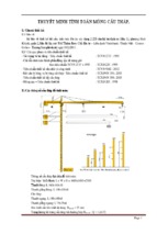
Chapter 3: GIRDER CONSTRUCTION
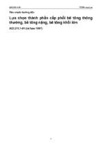
GIRDER CONSTRUCTION
Site Condition P3 Side (Bai Chay Side)
GENERAL VIEW OF THE BAI CHAY BRIDGE
903000
902500
129500
435000
129500
5200
11000
47499
47499
41000
Shin - so φ3000
l = 10.0m, n=3
Shin - so φ3000
l = 10.5m, n=3
P5
A2
26000
12000
8500
A1
6700
4000
12000
4000
21000
6000
2500
Shin - so φ2500
l = 9.5m, n=2
l = 9.0m, n=2
DL 0.000
HON GAI
40250
MAIN BRIDGE
6700
Shin - so φ3 000
l = 15.0m, n=4
29500
31Seg.
27X1750=47250 2500
32Seg.
40250
BAI CHAY
99000
40000
250 29500
750
5200
32Seg.
90000
27X1750=47250 2500
31Seg.
86000
2500
86000
2500
3000
35000
90000
250
750
P1
P6A
18000
6000
P3
P2
17000
P4
5
ERECTION OF TRAVELLER
1
2005
JUN 23
3
4
5
24
6
7
8
SHIN-SO
AUG 25
9
17 X 9 (10) DAYS
13
OCT 27 WALL
14
SIDE
SPAN 1 X 12 DAYS
15
16
17
18
NOV 28
9
1
2
10
11
12
13
14
15
16
17
18
19
20
21
22
23
24
DISMANTLE OF J/F
25
JAN 30
FEB 31
MAR 32
27
28
30
31
◆P6A Connection
SEP 38
NOV 40 COMPLETION OF WORK
DEC 41
◆Removal Form Traveler
17
18
11
12
19
12
13
20
13
14
21
14
15
23
16
17
18
22
15
1 X 12 DAYS 1 X 12 DAYS
16
17
18
DISMANTLE OF J/F
24
2
3
4
5
6
7
8
9
17 X 9 (10) DAYS
10
11
12
13
14
15
17
18
19
20
20
21
21
22
23
23
24
24
25
25
12 X 9 (10) DAYS
26
27
27
28
22
23
COLUMN TOP PIER TABLE
ROAD
WORKS
24
25
26
12 X 9 (10) DAYS
27
28
28
29
12 X 9 (10) DAYS
29
30
30
31
31
TRAVELLER BACK
1 X 12 DAYS
16
19
TRAVELLER BACK
32
30
31
SIDE
SPAN
32
DISMANTLE OF TRAVELLER
WORKS
DEMOBILIZATION
OCT 39
◆Center Closure
17 X 9 (10) DAYS
ANCILLARY &
ELECTRICAL
TARGET COMPLETION OF WORK
16
9
10
11
CLOSURE POUR
36
AUG 37
17 X 9 (10) DAYS
10
CLOSURE POUR
JUN 35
JUL
9
29
DISMANTLE OF TRAVELLER
15
8
26
MAY 34
2006
◆P1 Connection
8
22
12 X 9 (10) DAYS
14
7
29
APR 33
◆P2,P5 Connection
7
26
ROAD
WORKS
13
6
21
COLUMN TOP PIER TABLE
12
5
6
9
11
4
5
1
8
10
3
4
20
20
21
22
23
24
2
3
19
19
DEC 29
20Seg/32Seg
140m Cantilever
6
7
8
0
5
ERECTION OF TRAVELLER
TET HOLIDAYS
SUPERSTRUCTURE
10
11
12
SEP 26
Nov.2005
1
7
2
1
2
3
4
0
6
MAY 22
JUL
TOWER
SUPERSTRUCTURE
◆Cycle of Cantilever Work
PIER
APR 21
2
3
4
1 LIFT~24 LIFT
1 LIFT~24 LIFT
1
TOWER
BASE
MAR 20
◆Form Traveler Assembling
ERECTION OF J/F
ERECTION OF J/F
FEB 19
◆6.5m/Seg.
PIER TABLE
PIER TABLE
JAN 18
SUPERSTRUCTURE
9.9m*2=19.8m
◆Pier Table 9.9m*2=19.
8m
DISMANTLE OF TRAVELLER
TET HOLIDAYS
P1
P2
Pier Table Construction
Form Traveler Assembling
◆Limited Area
◆Inside Tower Crane Radius
◆Limited Weight 135 ton Form Traveler
Form Traveler Assembling
Form Traveler Assembling
Form Traveler Assembling Completion
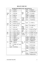
Main Girder Section
25.3m
8.00
2.50
.25
2%
2%
3.20
3.65
8.00
.25
.20
.56
2.50
.40
25.30
3.00
3.75m
5.25m
350mm
200mm
◆One-Cell
◆Steel Bracing Pipe
◆ 5m Long Wing
(interval 3.25m, Square Type thk=16mm and
Round Type thk=9mm)
◆ 45Deg Web
.40
PC Bar & Strand Position
Longitudinal PC Bar Φ32 (40-30Nos/Seg) from 4Seg.30Nos
Transverse PC Strand S21.8 (18-12Nos/Seg from 5Seg 12Nos)
Longitudinal PC Strand 12S12.7 (Center span 18Seg 20Nos,
Side span 24seg(P3),22Seg(P4) 10Nos )
Detail of Steel Bracing Pipe (Square Type)
PC Strand 12S15.2
Stay Cable
Formwork Tube
PC Bar Φ26
Dead Anchor
Square Steel Pipe
□250x250, t =16
Steel Bracing Pipes
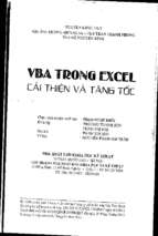
3.1 Gider Cycle Schedule
1st day
▪ Casting concrete
2nd day
▪ Curing for concrete
▪ Removal stop end form
▪ Roughing of concrete surface
3rd day
▪ Stressing
▪ Launching of traveler
▪ Setting up form
(External and Bottom)
4th day
▪ Installation of bottom slab and web rebar
5th day
▪ Installation of bottom slab and web rebar
( Steel brace foundation part)
▪ Installation of steel pipe brace
▪ Inner form and upper slab form Setting
6th day
▪ Installation of form for upper steel brace part
▪ Installation of Form Tube
7th day
▪ Re-Bar for stay cable anchor position
▪ Installation of upper slab rebar
8th day
▪ Installation of upper slab and PC materials.
▪ Final Form and Form Tube adjustment
Cantilever Work Concept
1st ( /
)
C uring
M ain
Activity RailB eam Launching
Rem ovalEnd Form
2nd ( /
)
Tensioning
Form Traveler Launching
Form C leaning & Form O il
3rd ( /
)
Form Setting
Low er Re-B ar Installation
Form W ork C hecking and
Repairing
4th ( /
)
Low er Re-B ar C om pletion
Inner Form Setting
B racing Pipe setting
C onstruction Joint chipping
Inspecti
on Item
Transverse Tendon
tensioning inspection
PC -Strand 15.2m m M aterial
inspection
LongitudinalPC B ar Φ32
tensioning inspection
B racing Pipe Assem bling
Inspection
B racing Pipe 15.2m m tensioning inspection
5th ( /
)
U pper Re-B ar Installation
PC -M aterialArrangem ent
6th ( /
)
U pper Re-B ar Installation
PC -Strand Installation
Form Tube setting
G rout H ose setting
Transportation Jack Pum p
PC C oupler connection
inspection
PC strand position
inspection
FinalInspection for C asting
PC -B ar setting inspection
U pper Re-B ar inspection
C asting Inspection
Low er Re-B ar Inspection
B racing Pipe setting
inspection
Form tube setting
inspection
Form inspection
C om pletion inspection for
C ast Segm ent (After 100%
cable stressing)
PC -Strand m aterial21.8m m
inspection (Rust checking)
PC -B ar m aterialinspection
before inserting.Taping
condition
Elevation of Form checking
Form Traveler Form Setting
C hecking list
Re-B ar for U pper Slab
Form Traveler checking list
for launching
Re-B ar for B ottom Slab
and W eb
PC B ar Arrangem ent & PC B ar m arking by tape for
proper coupling.
Transverse Strand
Elevation checking.(1T22)
Stressing PC B ar dia 32.
Survey M arking
C onfirm ation (C enter
,Elevation and Transverse)
Stressing PC strand 1T22
C oncrete C hipping
C ondition
C leaning W aste C oncrete
M &H and Vinaconex
C uring C ontrolling on site.
C leaning w ork after
concrete casting.
Precam ber value
confirm ation for form
setting
H and railm aterial
arrangem ent for Form
Traveler launching
Inner Form Elevation ,
C enter line C hecking
Inner form cleaning and
replacing dam aged form
G rout hose checking and
num bering,hose band
connection taping
Form Traveler before
casting check list
C leaning condition check
by Torch Lights corners of
bottom form s.
Pum p and concrete pipe
arrangem ent for M &H .
Tow er C rane & Truck
arrangem ent
B ottom finishing.1tim e
w ooden trow eland 1tim e
steeltrow el.
Location and Angle
checking of B racing Pipe
PC -B ar length checking
W aste concrete basket
setting up.
C hecking G rout H ose by
Air after concrete
casting.PC -Strands shallbe
m oved to check clogging.
C hecking list shallbe
prepared.
Location and Angle of Form
Tube checking
Form traveler anchor
position check
Transverse tendon
anchorage treatm ent
C uring w ater preparation
(m agic w ater)
C oncrete B lock rem oval
from deck.
W aste B asket preparation.
H ook re-bar arrangem ent.
Form oilfor box.
Re-bar m ortar painting for
prevention rust.
Tow er crane arrangem ent
for concrete block rem oval
C om pressor arrangem ent
for grout hose checking.
Transverse Anchor head
treatm ent.(C oncrete cap)
W eather forecast checking
for concrete casting
Arrangem ent for rain.Roof
sheet
B olt setting for elevation
m onitoring.(B ench M ark)
C hecking W eb portion
com paction
C oncrete com paction
C hecking foot of bracing
pipe.
Transverse G roup
C ontrolling before
Form oilapplying
launching for cutting
strands.
Keeping Jack & Pum p
B racing Pipe assem bling
properly,covering by
C hecking and D ead
sheets.
Anchor Setting
Stressing B racing Pipe(After com pletion ,im m ediately
inform to Stay C able Team .
Stressing PC B ar 26 for B racing Pipe
Lighting system for
launching.W ork becom e
late)
C leaning W ork
B lock O ut form Setting
Stop End Form Reterder
Form Traveler C hecking list
before launching
Electric cable arrangem ent
for Jack & Pum p
Tensioning Record for stressing bracing pipe
C oncrete m aterialstock
checking
Rem ovalTransverse
Anchorage treatm ent form
Tensioning Record Stressing PC B ar 26 for B racing Pipe
C uring m at and w ater
preparation
O pening form B lister,inner
form and bottom of B racing
pipe to check honeycom b.
Vinaconex Re-B ar m aterial
transportation and
arrangem ent
PC M aterialArrangem ent
Elevation m arking for bench
m ark.After Stay cable
tensioning 100%)
Repairing H oney C om b
Survey arrangem ent for
after launching(B oth side)
Form Tube M aterial
Arrangem ent
Survey arrangem ent for
after concrete casting
Stop End form Reterder
C hecking G round C onditon
to confirm the accessibility
of truck m ixers.
B racing Pipe C able
Previous Segm ent C utting
C hecking W ater Tank
C apacity and volum e.
Separate W ork and D aily Activity
G routing W ork
C leaning Surface W ork
Request for Inspection
Arrangem ent
8th ( /
)
C oncrete
Form Tube C onfirm ation
C oncrete B lock rem ovalfrom deck.
B racing Pipe PC -B ar Φ26 tensioning inspection
Arrange
RailB eam Relocation
m ent
checking list
7th ( /
)
U pper Re-B ar Installation
Form Tube Adjustm ent
D aily Report C hecking
C oncrete com paction
checking for blister
Vibrators controlling,
m inim izing hitting D ucts.
C oncrete can not be run
m ore than 1m basically.
Spraying w ater for
construction joints.
Plastic sheet for shading.
Avoiding sunshine for
concrete.
Lighting system
confirm ation for finishing
.(N ight tim e activity)
3.2 Cantilever Cycle Schedule
Date
1
Description
Casting
Concrete ( 90m3/block )
2
Curing
4
5
Rail Beam Relocation
Traveler Move and Fix
7
8
Form Down and Launching
Removal of Stop end and Internal form
Formwork
External and Internal Slab
Re-Bar Material Arrangement
Rebar work
Internal Web and Anchorage
Web and Bottom Slab
Form Adjustment
Upper Slab and Anchorage etc.
Upper Slab
Installation for PC
Bracing Pipe & Form Tube Setting
Brace Steel Pipe and PC Strand
・
C oncrete
・
Stressing
・
Bracing Pipe Assem bling
・
Rebar and PC of W eb
and Bottom Slab
Inspection
Date
1
Description
Casting
Concrete ( 90m3/block )
2
Curing
3
4
・
Stressing
5
・
Rebar,PC ,
and Form
6
7
Rail Beam Relocation
Traveler Move and Fix
Removal of Stop end and Internal form
Formwork
Form Down and Launching
External and Internal Slab
Re-Bar Material Arrangement
Rebar work
Internal Web and Anchorage
Web and Bottom Slab
Form Adjustment
Upper Slab and Anchorage etc.
Upper Re-Bar
Installation for PC
Bracing Pipe & Form Tube Setting
Brace Steel Pipe and PC Strand
・
C oncrete
・
Stressing
・
Bracing Pipe Assem bling
Inspection
・
Rebar and PC of W eb
・
Stressing
and Bottom Slab
Installation
Stay Cable
Girder Survey
◆Morning Time Survey
8
Removal of Laitance
Stressing
Pre-Stressing
Center Span
6
Stressing
Pre-Stressing
Side Span
3
Removal of Laitance
After casting
After Launching
Stressing 80%
・
Rebar,PC ,
and Form
Stressing 100%
After 80%
After 100%
Form&Form
Tube
Adjustment
1
1stDay
2
Casting Concrete Bottom Slab
1stDay
Casting Concrete Upper Slab
1stDay
Casting Concrete
1stDay
Curing Concrete
2Days
- Xem thêm -