DEVELOPMENT AND DESIGN OF NEW STEEL PIPE
INTEGRATED PIER WITH SHEAR LINK
Ryohei NAKAMURA1*, Hidesada KANAJI1, and, Takashi KOSAKA1
Abstract
We proposed an innovative integrated steel pipe pier using damage control
design. The proposed pier is composed of four steel pipes interconnected with shear
links along its height. Steel pipes as main members, support vertical load (such as dead
load and live load). Shear links as sub members resist horizontal load (such as seismic
load). The application of the damage control design can reduce a response of the pier
and it can keep steel pipes wholesome during earthquakes. So, not only emergency
vehicles but ordinary vehicles can pass immediately after earthquakes. This paper
describes a outline of design and construction of highway viaduct supported by new
steel pipe integrated pier with shear links applied to Ebie junction which connects the
Yodogawa-sagan route to the Kobe route of Hanshin expressway.
Introduction
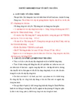
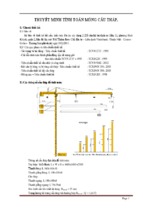
The proposed pier, steel pipe integrated pier with shear link, is composed of four steel
pipes interconnected with shear links along its height (see Figure1). Steel pipes as main
members, support vertical load (such as dead load and live load) and shear links as
sub-members resist horizontal load (such as seismic load). The stable elastic-plastic
behavior of each shear link as hysteretic dampers, which reduce the response of the pier
during an earthquake. The application of the damage control design can reduce a
response of the pier and it can keep steel pipes wholesome during earthquakes. So, not
only emergency vehicles but ordinary vehicles can pass immediately after great
earthquakes. And when a restoration is required, a change of shear panels restore the
proposed pier. Therefore the seismic life cycle cost can be reduced.
Fig-1 Steel pipe integrated pier
________________________
1
Hanshin Expressway Company Limited, Osaka, Japan
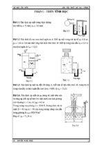
This paper describes an outline of design and construction of highway viaduct
supported by new steel pipe integrated pier with shear links where is Ebie junction
which connects the Yodogawa-sagan route to the Kobe route of Hanshin expressway
(see Pictuire1). The basic seismic performance of the proposed pier was reported in
documents 1).
Kobe
Osaka Harbor
Kyoto
Yodogawa River
Kobe Route
of Hanshin Expressway
PD4 pier
Steel Pipe Integrated Pier
With Shear Link
Yodogawa-sagan Route
of Hanshin Expressway
It is opened for traffic on May 25, 2013.
Picture-1 Ebie junction
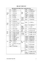
1. Required performance
A required seismic performance matrix of steel pipe integrated pier is shown in
Table 1. The required seismic performance of 4 phases is determined in checking a
design of the proposed pier. It has been thought that it is difficult to control damages for
great earthquakes in terms of cost performance so far.
Table-1 A required seismic performance matrix of steel pipe integrated pier
The application of the damage control design enables the proposed pier to control
damage of main member. The proposed pier should be intact for Level 1 earthquake
(Seismic performance I). This design method leads major damages into shear panels
that connect each steel pipe for level 2 earthquake and keeps steel pipe pier structural
elastic-region. Structural elastic-region mean a state that a member makes locally
plastic, shows elastic behavior as a structure, keeps sound state and the road can be
open to the public after earthquake.
To keep small damage is illogical subject to design condition that a pier such as PD4
pier in Ebie junction resists seismic load in a curved and long span bridge. So this
design method allows medium damage, same level as specifications for highway
bridges, subject to special design condition (Seismic performance IIb). And this design
method allows big damage of the proposed pier on less important structure (Seismic
performance III).
2. Member Soundness
Seismic performance of the proposed pier is composed of soundness and damage
level of each member. Member soundness matrix for seismic performance of the
proposed pier is shown in Table 2. An image of damage level of each member is shown
in Figure 2.
Table-2 Member soundness matrix for seismic performance of the proposed pier
Fig-2 Steel pipe integrated pier
As regards seismic performance Ⅰ, all members except shear panel should satisfy
soundness 2 which have a safety factor for yield resistance. And the stress of shear
panel is below yield resistance. As regards seismic performance Ⅱa, steel pipe pier
should satisfy soundness 2 which is structural elastic-region, shear panel should satisfy
soundness 3 which has stable performance, Horizontal member and connection should
satisfy soundness 1 which is below allowable stress. As regards seismic performance
Ⅱb, steel pipe pier should satisfy soundness 3 which is limiting value for steel pipe pier
ruled on specifications for highway bridges. As regards seismic performance Ⅲ, steel
pipe pier should satisfy soundness 4 that steel pipes don’t collapse, joints between
shear panels and steel pipes satisfy soundness 3 which is below load capacity.
3. Analysis Model
The model of the proposed integrated steel pipe pier was created using a fiber model
of the beam elements. A biaxial moment and a change of axial load are considered in
this analysis. And material nonlinear configuration rules and geometrical nonlinear are
considered also. The analysis model of the highway viaduct supported by steel pipe
integrated pier is shown in Figure 3, the fiber model is shown in Figure 5 (a) and the
fiber cell division of the steel pipe and shear link cross-section is shown in Figure 5
(b)(c)(d). The relationship between shear stress and shear strain is shown in Figure4.
Fig-3 The analysis model for of Highway Viaduct Supported by New Steel Pipe
Integrated Pier
Fig-4 The relationship between shear stress and shear strain
Fig-5 The fiber model of Steel Pipe Integrated Pier
4. Material Configuration rules
With regards to the material configuration rules, those proposed in the documents 2)
were used for SM490Y of the steel pipes, beams, horizontal structural member flanges,
and the material of the filler concrete. For the dynamic analysis of the strain hardening
of the steel materials, the bi-linear model, in which the secondary gradient should be
1% of the primary gradient, was used as the material configuration rule. A
representation of the relationship between the shear stress and strain of LY225, used for
the web plate of the horizontal structural members, is depicted as a bi-linear model.
5. Pushover Analysis
A pushover analysis was conducted to investigate the deformation performance, load
capacity, and plasticization rate. For the load, a dead load was applied in the vertical
direction and then a load was gradually increased in the horizontal direction. And a
fiber model and shell model for a horizontal member were analyzed to investigate an
acting of both models.
Fig-6 The load-displacement curve resulting from the pushover analysis of the
Shell and Fiber models
The load–displacement curve resulting from the pushover analysis of the both models
is shown in Figure 6. No significant difference of whole stiffness, a deformation
performance, and load capacity of both models was found. The load capacity became
larger after a shear panel was yielded. Whole bridge stiffness was controlled by the
stiffness of the piers except for PD4 after a shear panel yielded. The plasticization rate
(ultimate displacement / yield displacement) of the proposed type was determined to be
2.23. So absorption effects of energy can be expected in this structure.
6. Nonlinear Time History Response Analysis
This analysis was a time history response analysis incorporating geometrically and
materially nonlinearity. Six standard seismic waves (Type1:3waves, Type2: 3waves ),
commonly used for road bridges in Japan, were used. And three scenario seismic waves
(Nankai-Tonankai earthquake, Arima-Takatsuki dislocation earthquake, Uemachi
dislocation earthquake) were used also. Type III soil, a comparatively poor soil, was
employed, while the Newmark-beta method of numerical integration (β = 1/4) was
adopted. The dominant oscillation mode is shown in Table 3. The dominant oscillation
mode was in primary mode and secondary mode. In the both modes, PD4 pier was
warped as contrasted with other piers.
The time history response displacement of the top of the PD4 pier for standard seismic
wave (EW03) is shown in Figure 7. The maximum response displacement of the
longitudinal direction was determined to be 0.299m. The maximum response
displacement of the transvers direction was determined to be 0.360m. These response
displacements were corresponding to allowable residual displacement.
Table-3 The dominant oscillation mode
(a) Longitudinal direction
(b) Transvers direction
Fig-7 The time history response displacement of the top of the PD4 pier
In the case of severe seismic direction for PD4 pier, the maximum response strain of
steel pipes is shown in Table 4. The maximum response strain of shear panel is shown
in Table 5.The average of the maximum response strain of steel pipes on all members
was below 5εy correspond to soundness three of seismic performance IIb. Tension
strain was determined to be 4.17εy in the base of steel pipe, 3.35εy in the upper of 1st
horizontal member. Compressive strain was determined to be 2.45εy in the base of steel
pipe, 1.55εy in the upper of filled concrete section. The average of maximum shear
strain of shear panel was below 8% correspond to soundness three of seismic
performance IIb in all shear links. The shear strain of shear panel was determine to be
3.58% as maximum strain in the shear link of 2nd, 3.40% in the shear link of 3rd. It is
possible to thin thickness of steel pipe or reduces a number of shear links so that the
shear panel was below allowable strain for Level 2 earthquake. But we allow shear
panel to yield particularly during for Level 1 earthquake. As regards a number of shear
link, energy absorption of 4 links was larger than that of three links as a result of
comparison that of three shear links with that of 4 shear links during Level 2
earthquake.
Table-4 The maximum response strain of steel pipes
Table-5 The maximum response shear strain of shear panel (Unit :%)
7. Fabrication Accuracy of Steel Pipes
Spiral steel pipes applied to the proposed pier are usually supplied for piles. Therefore
the pipe suppliers don’t manufacture pipes with high accuracy such as steel piers. The
manual for design of the proposed pier3) requires that the steel pipe of the proposed pier
should meet the accuracy same as general ordinary steel piers. Differences of the
fabrication accuracy between the manual and JIS (Japanese Industrial Standards) A
5525 is shown in Table 6. If a manufacture supplied isn’t satisfied with the manual, a
fabricator must revise a manufacture to satisfy accuracy of steel pipes. In this
construction, a fabricator didn’t need to revise a manufacture so that the manufacture
supplied was satisfied with the manual. It seems the opportunity to use spiral steel
pipes for steel pier increase in the future. So we need to discuss with mill makers about
the accuracy of steel pipes.
Table-6 Differences of fabrication accuracy between the manual and JIS A 5525
8. Welding Workability
In the junction where a superstructure meets steel pipes, it is worried that an
interference of members and a deterioration in the quality of welding workability. So
we made sure about interferences of members and the deterioration of welding
workability using 3D-CAD. A example of checking interferences of members are
shown in Figure 8. Situations of checking the quality of welding workability using full
scale model are shown in Picture 2.
(a) 3D CAD with Deck model
(b) 3D CAD without Deck model
Fig-8 3D-CAD example for checking interferences of members
(a) Full scale model
(b) Situation for checking the quality of
welding workability using full scale model.
Picture-2 Checking the quality of welding workability using full scale model
9. The outline of Construction
The construction flowchart of the proposed pier is shown in Figure 9. The proposed
pier under construction is shown in Picture 3 and 4.
Fig-9 Construction flowchart
Picture-3 A steel pipe under erection
Picture-4 The proposed pier under construction
10. Conclusion
This paper describes the outline of design and construction of highway viaduct
supported by new steel pipe integrated pier with shear links where is Ebie junction
which connects the Yodogawa-sagan route to the Kobe route of Hanshin expressway
(see Picture 5). The following conclusions were made:
(1) We proposed an innovative integrated steel pipe pier using damage control design.
This design method leads major damage into shear panels that connect each steel
pipe.
(2) The required seismic performance of four phases is determined in checking a
design of the proposed pier. It has been thought it is difficult to control damage for
great earthquake in terms of cost performance so far. The application of the damage
controlled design enables the proposed pier to control damage of main member.
(3) A pushover analysis was conducted to investigate the deformation performance,
load capacity, and plasticization rate. The plasticization rate (ultimate displacement
/ yield displacement) of the proposed type was determined to be 2.23.So absorption
effects of energy can be expected in this structure.
(4) As result of time response analysis, the average of the maximum response strain of
steel pipes on all members was below 5εy correspond to soundness three of seismic
performance IIb.
(5) Finally, this paper describes measures against problems on fabrication and the
outline of construction of PD4 pier, steel pipe integrated pier.
Picture-5 Steel Pipe Integrated Pier with Shear Link (Ebie junction)
11. References
1) Masatsugu SHINOHARA, Hidesada KANAJI:”Seismic performance of Integrated
Steel Pipe Bridge Pier”, IABSE Symposium London 2011: Taller, Longer, Lighter,
September 2011.
2) Steel Bridge Seismic Resistance Subcommittee of the Performance-based Design
Research Committee of the Japanese Society of Steel Construction: Fundamentals
and Applications of Seismic Resistant Design for Piers, September 2002.
3) Hanshin Expressway Company Limited: The manual for Design, Fabrication and
Construction of the Integrated Steel Pipe Pier, April 2011.
4) Masatsugu SHINOHARA, Hidesada KANAJI, Takashi KOSAKA, Tsutomu IMAI:
Design and Construction of Highway Viaduct Supported by New Steel Pipe
Integrated Pier with Shear Link, 9th German - Japanese Bridge Symposium,
September 2012.
- Xem thêm -