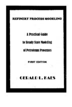
REFINERY PROCESS MODELING
APractiall Guide
to Steady State Modeling
01 Petroleum Processes
FIRST EDITION
REFINERY PROCESS MODELlNG
I
,I
i
I
A Practical Guide to Steady State Modeling
of Petroleum Processes
(Using Commercial Simulators)
First Edition
Gerald L. Kaes
Consulting Chemical Engineer
Chemicall'rocess Simulation
Colbert, Georgia
The Athens Printing Company
Athens, Georgia
Refinery Process Modeling
First Edition
ISBN: 0-9679274-0-4
Copyright (£)2000 by Kaes Enterprises, Inc.
All rights reserved. Printed in the United States of America.
This book or parts thereof may not be reproduced
in any form without permission.
Published by:
Kaes Enterprises, Inc.
522 Kingston Road
Colbert, Georgia 30628
Phone: (706) 788-3366
FAX: (706) 788-3366
emaiI:
[email protected]
First printing: March 2000
The In/orma!ion contained in this book is believed to be accurate and reasonable. However, the author
and;: aes Er.!erpri5cs, Inc. do not guarantee the accuracy or completeness of any in/ormatioll published
herelf1 and sha!t nol be responsible Jor any errors, omI5:,-;on5. -or damages arising out of the lIse oJthis
rn/orfTlQfi0n Titls book is published with the intent tn supply infurmation and is no! an attempt lo render
('ng; ,':eenng or other professional services. The user of infon,l(J[ion published herein is solely responsible
for .he acc;JrC0' and appl;cability ofcalculations based on this information.
They say that behind every good man is a good woman. Anything good I have
accomplished I owe to my wife Barbara who has encouraged and supported me these
many years. This book is lovingly dedicated to her.
f
F'-
At the urging of several colleagues, I decided to record many of the tips and tricks for
computer simulation of petroleum processes I have amassed over the past thirty-eight
years. In this way, perhaps I can partially repay the technical debt I owe to the many
engineers who helped me develop my skills as a young engineer. I was fortunate to begin
my career in an era when corporations sought to develop young engineers through
intensive training and apprenticeship programs. Unfortunately, the bottom line thinking
of today no longer allows such an approach. The young engineer is otlen thrust into a
plant environment with little or no training. Hopefully, this book will serve 10 some
small capacity to provide some practical training for the younger engineers.
If you are looking for technical elegance this may not be the book for you. Frankly, in
my experience with modeling petroleum refinery processes (with commercial simulators)
I have encountered little that is elegant. I chose to focus onthe more practical aspects of
engineenng. Engineering theory is good and necessary; however, it is based on perfect
processes and simplifying assumptions. Any practicing engineer knows it is necessary to
apply experience factors to reconcile theoretical expressions with real world processes.
This is the fOCllS of this book.
It is noteworthy to remind the reader that this book was written for steady state models
for petroleum processes. By definition, for a steady state process, there is always"
perfect mater'ial balance and heat balance. Any engineer who has conducted a plant test
knows that real plants seldom operate at steady state. This must always be taken into
consideration when developing steady state models.
I must also stress that this book was written for engineers who use commercial software
for their simuiation efforts. Because of the enormous overhead associated with
developing and maintaining simulation software, most corporations today have
abandoned their own efforts in favor of a vendor-supplied simulation program. While
this is the most cost-effective approach, it is not always the best technical approach.
Commercial simulators must be based on open literature methods. This does not allow
the use of proprietary data that might be useful in improving the accuracy of simulation
results
~
\:everthe!ess. it is possible to develop accurate and useful models for petroleum
processes ·..,ith commercial simulators. The author has had extensive experience with the
Hyprotecr.. Lld HYSIM, and HYSYS programs, and the SimSci PROVISION" program.
Howc\·cr. 'he principles in this book are not simulator specific and may be applied with
any simuialOf having tne features required for simulation of petroleum processes.
GcraIJ L Kaes
:
I
f
I
I
I
I
TABLE OF CONTENTS
Chapter 1 - Introduction to. Steady State Simulation •...•..••.••••••..•..•.••.•••••.•...•••••......... I
................... I
1.1 The Steady State Process ................................ ..
1.2 Dynamic Simulation .................... ....................... ............. .......................... 2
1.3 Steady State Simulation Program Features ....................................................... 3
1.3.1 Pure Compon(!nt Data Library ...................... .............. ........... .. ................ 3
1.3.2 Non-Library Components ............................................................................ 4
1.3.3 Thermodynamic Methods ............................................................................. 4
1.3.4 Physical and Transport Properties ........................................... ,.............. :....... 5
1.3.5 Simulated Laboratory Tests....... ............... ............... .............
....... 5
1.3.6 Unit Operation Calculations ......... ....................
.. ................................ 5
1.3.7 Special Flow Sheet Modules........ ....................
................
....... 6
..................................................... -/
1 .3.8 Graphical Interface......................
1.4 Steady State Simulation Programs....................
.. .......................................... 7
Chapter 2 - Composition of Petroleum Refinery Feed Stocks •..•...........••.................. 10
. 10
2.1 Crude Oil Properties ........................................................ .
2.2 Crude Oil Composition........ ..................................
.. ............................... 13
2.3 Crude Oil Assay....... ................................. .......................................
ff
!
2.4 Crude Oil Blending ................................. ..
.... 13
.. 14
Chapter 3 - Laboratory Testing of Petmleum Streams ...........................•..••.....•.•..... 16
3.1 True Boiling Point Distillation (TBP) ........................................................... 16
3.2 ASTM 086 Distillation ................................................................................. 17
3.3 ASTM 01160 Distillation ............................................................................. 18
.j
3.4 API Gravity ............................................ .
................................ 19
3.5 Reid Vapor Pressure (R.V.P.) ................. ..
...... ~ ......................... 19
3.6 Chromatographic Simulated Distillations.. ...... .
1:.•
.~)
3.7 Flash Point
. ......... .
3.8 Pour Point ............................ ..
3.9 Viscosity
'i
........... ............
...... 20
................................. 22
................. 22
')-
.......................... .
................................. _J
3.10 Octanes ............................. .
.......................................... 23
3.11 Cetane ................... .
................ '>'
L-'
Chapter 4 - Developing Petroleum Pseudo-components ............................................ 25
4.1 Pseudo·component Normal Boiling Points ......................................................... 25
4.1.1 Conversion O'fD86 DistillatIons ....................................................... :..... 26
4.1. L I 086 Cracking Corrections .............................................................. 28
5
TABLE OF CONTENTS (continued)
4, I ,2 Conversion of D I 160 Distillations"""",." ""'''''''''''''''''' """,," ." .. " "".". ".29
4.1.3 Conversion of Simulated Distillations ".".""."""".""".".".,,"",, .... ,," ".",29
4.1.4 Selection of TBP Cut-point Ranges .. """"",,, .. ,,.,,,,.,,.,,,,,,,,,,,,,,,,,,,,,,,,,,,,,.,, 31
4,2 Development of Pseudo-component Gravities" ".",,'" ""''''''''''''''''''''''''''''
.33
4,3 Development of Pseudo-component Molecular Weights ""'"'''''''' """"".'
.. 35
4.4 Pseudo-component Enthalpies and Critical Propenies "'''''""".""".""""". """ 36
Chapter 5 - Limitations of Petroleum Pseudo-components .•...........••............•...•....... 37
. 5. I Prediction of Laboratory Distillations"""""" " ....... """"""",:.. ,,""",.,,"",, .. ,,'" 37
5.2 Prediction of True Stream Composition '"''".".".".,,'''
.... ".,.,"""""',.", ... ,38
5,3 Simulation of Refinery Reactors """ ... "".""."",,.,,'"
",,,,,,,,,.,,,,, ... ,, .. ,,,39
5.4 Simulation of LlIboratory Tests "'''''''''''''''''''''''''''''''''''''''''''''''' "".""".,, " .. ,,", 40
Chapter 6 - Thermodynamics for Petroleum Calculations .............•.••••••...•....•...••..••. 43
6.1 Equilibrium K Values
.... _.... __ ................................. _ ......... 43
6,2 Effect of Non-Hydrocarbons on K values",,,,,,,,,,,,.,,,,, """"" ,",,"""'''' ,.""".,44
6.3 H ydrocarbon-Water Systems"",,,,,,,,,,,,, ."." ... " """"""" "".".""".""""".", 4 5
6,4 Enthalpies". ",,"" "".""""""",,,,,,,,,,,,, '" ."."""."." '" """."."."",,"""." ,,46
,
6,5 Recommended Methods for Petroleum Systems .. " .. ,," """"""""""""",,,,, ".46
6,6 Thermodynamic "Rules of Thumb""""""".
":.;~~
.... ".".,"',.,",""',.,' ..... 48
Chapter 7 - Practical Distillation Principles ................................•.•....•.•.................. ".52
7.1 Theoretical Considerations""""
."., "".,,""
"" ... """."",,""''', 52
7,1.1 Inside-out Distillation Algorithm "".""" ..... ",,. '''''''".""."".".,,'''',,' """" 53
7. 1.2 Column Conventions"."""""" """"".". "" ,,,,,,,,,""''',, """"""."""",,,.,,,, 54
7, I ,3 Initial Solution Estimates" """ """ "" ". "".,,"'" ""," "" """ """""",,, "" "" 56
7.1.4 Non-converged Column Solutions ",,""",,"'''''''' ""'""""""."",,"" """.56
7.2 Simulation of Existing Columns
.. """"""", ..
7.2, I Gathering the Information".""""", """""""
7,2,2 Defining the Separation Zones ".",,""''',,'''''' ..
7,2,3 Translation of Actual trays to Theoretical Trays.
7,2.4 Defining Performance Specifications" ,,,,,,,,,,,
7.2.5 Tray Rating ""''''''''''''''",'' .. "",,",,.
"""".,,"",,"",,. """~'" 58
"","""""" .... "",,""",, 58
""""""""""",,.,,""",, S9
""""""""" ,," ,,,,,,,,,,64
"""""'" """""""",67
""""".". """" 71
7,3 Troubleshooting Actual Columns """""", .
7,3.1 Difficulties Matching Real Column Operations
7,3,2 Diagnosis of Column Operational Problems, "''''''",
}
'.1
:i
,
"
"","" 72
,,,,,,72
""""",76
Chapter 8 - Crude Distillation ....... "" ......................................................................... 81
8.1 Crude Distillation Units General Information.".""""". """.""""""""",,.,, "",82
8,1.1 Process Description '''"" ".",,""" ."""."".",,.
""""""."."",,. "."""".83
8. 1. 2 Typical Ope, at ions and Control "" ..... """.".,,
"."""."""."'" .".,," 87
6
'1
TABLE OF CONTENTS (continued)
. C apacny
. ........................................
.
8.1.3 Schemes to Increase C rude Processmg
. 90
8.1.3.1 Main Column Co·nsiderations .............................................................. 90
8.1.3.2 Furnace Capacity Considerations ........................................................ 93
8.2 Crude Distillation Units: Simulation of Existing Columns .......... __ ........ __ ........... 95
8.2.1 Definition of the Crude OiL.......... . ............................................. 95
8.2.1.1 Crude Assay Data............ ........... ..... . .........
. ............. 95
8.2.1.2 Crude Oil Data from Product Blending ... ..................................... " 98
8.2.2. Collection of Operating and Laboratory Data ..........................
. ..... 106
8.2.3 Translation of Actual Trays to Theoretical Trays ................................... 108
8.2.3.1 Main Column Stripping Zone ........................................................... 109
8.2.3.2 Main Column Flash Zone.........
. ......................................... 109
8.23.3 Main Column Wash Zone ............ __ . . . . . ...................................... 110
8.2.3.4 Pumparound Zones ....................................................................... 110
8.2.3.5 Side Product Draw Zones.,................ . . . ....................................... 112
8.2.3.6 Top Section of Main Column ........................................................... 112·
8.23.7 Side Stripping Columns .............................................................. 113
8.2.4 Crude Column Overhead System ........................................................... 113
~.25 Solution Techniques: Inside! Out Column Algorithm ............................... 114
8.2.5.1 Initial Estimates ..................................... ........................................ liS
8.2.5.2 Initial Model Phase................................ ................................... 115
8.2.5.3 Tuning the Model ......................................................................... 116
Chapter 9 - Vacuum Distillation .......•..... _................................................................. 119
9.1 Vacuum Distillation: General Information .......... ........................... ____ ... __ ... 119
9.1.1 Process Description .......... __ .... __ .... __ ..... __ ... . . . ... __ .............. __ .. __ ..... __ .... __ 119
9. I .2 Typical Operations and Control... .. __ .... __
.......... __ ............ __ .... __ .... __ ...... 123
9.2 Vacuum Distillation Units: Simulation of Existing Columns ... __ .. __ ........ __ ..... __ .. 129
9.2.1 Definition of the Topped Crude Oil .. ____ ....... __ ............... ____ .. ____ .... __ .... __ ... 129
9.2.1.1 Crude Assay Data ____ .. __ .................. __ ... .. .............. __ ........... :............ 130
9.2.1.2 Topped Crude Oil Data from Product Blending................................. 130
9 2. I.3 Molecular Weight Estimation .... ............ .............. ...................... . 131
9.2.2 Adjustments to the Topped Crude Oil.
............................................ 131
9.2.3 Collection of Operating and Laboratory Data ................~..
.. ............. 134
9.2.4 Translation of Actual Configuration to Theoretical trays ......................... 135
9.2.4.1 Steam Stripping Zone for Wet Vacuum Units ................................... 136
92.4.2 Boot Cooler Circuits.......... ..............
.. ................................. 136
9.2.4.3 Light Gas Oil Zone ..............
. ......................... 137
9.2.4.4 Heavy Gas Oil Zone ............. .
.. .................... 138
9.2.4.5 Wash Grid and Flash Zone....
.. __ ..............
138
9.2.5 Solution Techniques: Inside/Out Algorithm ....................................... 140
92.5.1 Initial Estimates ................. .
........... ......................
141
92.5.2 Initial 1--10del Building Phase............. ................
...141
9.2.5.3 Tuning the Model .............. .
. ............................. 145
Chapter 10 - Refinery Reaction Systems .................................................................. 148
7
TABLE OF CONTENTS (continued)
10.1 Reactor Processes- General Information ......................................................... 148
10.1.1 CatalyticCracking ........................... ~ ................................................, .... 150
10.1.2 Hydrocracking and Hydrotreating ........................................................... 153
10.1.2.1 Hydrocracking ................................................................................ 153
10.1.2.2 Hydrotreating ................................................................................. 157
10.1.3 Reforming and Isomerization .................................. ............. ............. 160
10.1.3.1 Catalytic Reforming .....·.................... ............
.160
10.1.3.2 Isomerization ............................................................................. 164
10.1.4 Alkylation and Polymerization ..............................
.. .................. 167
10.1.4.1 Alkylation ................................................................................... 167
10.1.4.2 Catalytic Polymerization................................ ............. .. ............ 172
10.1.5 Thermal and Coking ........................................~........
. ......... , ....... 174
10.1.5.1 Visbreaking ............................................................................... 174
10.1.5.2 Coking............................................................... ............. 178
. ............. 181
10.1.6 Hydrogen Plants ......................................... :...............
10.1.7 Ether Processes .................................................................................. 183
10.1.7.1 MTBE Processes ......................................................................... 183
10.1.7.2 TAME Processes...........................................
.. ............. 186
10.J Reactor Processes: Simulation Techniques........................... ...
.. ..... 188
JO.2.1 Black Box Reactor Mode!... ....................................................... :........ 188
10.2.2 l\·1odified Black Box Reactor ................ ...........................
.. ........... 190
10.2.3 Empirical Predictive ReactoL....... ....... ................... ..........
.. ........... 193
10.2.4 Free Energy Minimization Reactor (Gibbs) ............
.. ........... 196
10.2.5 Equilibrium Reactor .............................................................................. 198
10.2.6 Stoichiometric Conversion Reactor ................... ............. ....... 200
Chapter 11 - FCC (Fluid Catalytic Cracking) Processes .•....................................... 204
I
I
I
ILl FCC Proces,,,s: Generallnformation ........................................................... 204
11.1.1 Process Description ............................. ................... ............ .. ............... 205
11.1.2 Typical Operations and Control.. .......................................................... 207
11.1.2.1 FCC Reactors ..............................................................
.. ..... 208
11.1.2.2 Main Fractionators........................................
.. .............. 208
11.1.2.3 Slurry Strippers...............................................
. ........... 211
11.1.2.4 FCC Gasoline Splitters...................................
..~ .... 2!2
11.1.2.5 FCCGasPlants........................................
. .... 212
.. 217
11.2 FCC Processes: Simulation of Existing Units .............. ..
. .... 217
11.2.1 Definition of the Reactor Effiuent... ..................... .
11.2.2 Collection of Operating and Laboratory Data ..... .
.. 220
11.2.3 Reactor Modeling ......................................... ..
. . . . ......... 222
.. .... 223
112.4 Main Fractionator ............................................... .
11.2.4. I Quench (Desuperheating) Zone .................................. .
.. .. 224
112A2 Heavy Cycle Oil Zone ................................ ..
.... 225
11.243 Light Cycle Oil Zone................................. . .......................... 226
11.244 Heavy Naphtha Zone ....... ......................
. .................... 227
11.2.4. 5 Overhead System
.........................................
.. .............. 228
8
TABLE OF CONTENTS (continued)
I
1
I
!
11.2.5 Gas Plant Columns ...................... :......................................................... 229
11.2.5.1 Primary Absorber.. ......................................................................... 229
.............. 230
' er ........................................................... .
11 ..
2 5 ' 2 St npp
.. .... 230
11.2.5.3 Secondary Absorber............................ ........... ...........
11.2.5.4 Stabilizer.......................................................
. ............. 23)
11.2.5.5 C3! C4 Splitter...............................................
...... .....
.. ....... 23]
11.2.6 Recycle Loops...............................................
. .... 232
.. ....... 232
11.2.6.1 Recycle Estimates............................... ........... .
11.2.7 Solution Techniques: Inside! Out Column Algorithm...
...... 233
I 1.2.7. I Initial Estimates: Main Fractionator.. ..... ...........
.. ...... 233
I i .2.7.2 Initial Estimates: FCC Gas Plant Columns ......
...: .... 233
11.2.7.3 Initial Model Phase ..................................................................... 234
11.2.7.4 Tuning the ModeL......................................... .
. ....... 234
Chapter 12 - Catalytic Reforming Processes ............................................................ 236
12.1 Catalytic Reforming Processes: General Information ........ .......................... 236
12. I. I Process Description ............................................................................. 237
12.1.2 Typical Operations and Control.......... ...........
.. ............................ 239
12.1.3 Catalytic Reformer Reactors.......................................
. .......... 241
12.1.4 Reformer Separator Operations............................ ............... .
.. ....... 242
12.1.5 Stabilizer Tower Operations ....................................
.. ... 242
12.2 Catalytic Reforming Processes: Simulation of Existing Units...
.. ............ 243
12.2.1 Definition of the Reactor Effiuent... .................................................... 243
12.2.2 Collection of Operating and Laboratory Data . . . . . . . . . . . . ......... 245
12.2.3 Reactor Modeling............. ..............................
.. ...... 246
12.2.4 Stabilizer Modeling .......... ................................... .. ......................... 248
12.2.5 Recycle Loops..........................................................
.. ................ 248
12.2.5.1 Recycle Estimate ...... ... ..................................
.. .................... 249
.. .................. 249
12.2.6 CCR Catalyst Systems...........................................
12.2.7 Solution Techniques ........................................................................... 249
12.2.7.1 Blocked Operations ..................................................................... 250
Ch apter 13 - Hydrogen Processes .•.............................•...................................•.......•• 251
~
13.1 Hydrotreating Processes: General Information .... .
13. 1.1 Hydrotreating: Process Description ............. ..
13 I 2 Typical Operations and Control.. ............... ..
13 I 3 Hydrotreating Reactors .......... .
13. I .. Separators! Gas Treating .......................... ..
! 3 I 5 Product Stabilizers (Strippers) ...................... .
.. ................. 251
.. ...................... 252
.. .......... 253
.............. 255
. ........ 255
.. .... 256
13 2 H\drotr~ating Processes: Simulation of Existing Units....... .................. 256
13.2 I Definition of the Reactor Effillent....................
. .......................... 256
13.22 Collection of Operating and Laboratory Data
............. .. 258
13.2.3 Reactor Modeling............ ............
.. .................. 260
13.24 Modeling Separators! Gas Treating.......
.. .................... 262
132.5 Modeling Stabilizer (Stripper) Columns... ..............
. ..................... 262
9
),:
- TABLE OF CONTENTS (continued)
It
13 .2.6 Recycle I Purge Gas Calculations ......................................................... 263
13.2.6.1 Initial Estimate for Recycle Hydrogen............................................. 264
13.i.7 Solution Techniques ........... ~ ................................................................. : 265
13.2.7: I Blocked Operations..................................................................... 265
13.3 Hydrocracking Processes: General Information .......................................... 266
13.3.1 Hydrocracking: Process Description.................
.266
13.3.2 Typical Operations and Contro!...........
.. ............................ '267
13.3.3 Hydrocracking Reactors..................
. .......................................... 269
13.3.4- Separators! Gas Treating.......................................................................... 269
13.3.5 Quench Hydrogen ............................................................................ 270
13.3.6 Product Separation ......................................................................... 270
;
13 A Hydrocracking Processes: Simulation of Existing units ............,.. ............
.. 270
13.4.1 Defmition of the Reactor Effiuent......................... ...............................271
13.4.2 Collection of Operating and Laboratory Data ......................................... 272
13 A.3 Reactor Modeling ................................................................................. 274
13A.3.1 Heat of Reaction ........................................................................... 276
\3 A. 3. '2 Reactor Calculations for the Design Case..
.................... '277
13.4.4 Modeling Separators! Gas Treating......................................... .279
13.4.5 \
- Xem thêm -


