PREFACE
This second edition represents a major update and revision of
the ASHRAE Air-Conditioning System Design Manual. The
request that drove this revision effort was simply to make a successful resource more current. The revision process involved a thorough
editing of all text in the manual, the addition of SI units throughout,
the updating of references, and the editing of many illustrations.
New material dealing with design process, indoor air quality, desiccant dehumidification, and “green” HVAC&R systems was added.
The editor acknowledges the active assistance of a Project
Monitoring Subcommittee (with Warren Hahn as Chairman) from
ASHRAE Technical Committee 9.1, which supervised the revision
of this manual. The editor and committees are grateful to several
individuals who reviewed all or parts of the draft of this revision
and made valuable suggestions for improvements and clarifications
(see list of contributors). Andrew Scheidt, University of Oregon,
provided graphic assistance for the editing of many illustrations.
Walter Grondzik, PE, Editor
ix
ACKNOWLEDGMENTS
LIST OF CONTRIBUTORS
Final Voting Committee Members
Dennis J. Wessel, PE, LEED
Karpinski Engineering, Inc.
John L. Kuempel Jr.
Debra-Kuempel
Stephen W. Duda, PE
Ross & Baruzzini, Inc.
Kelley Cramm, PE
Integrated Design Engineering
Associates
Rodney H. Lewis, PE
Rodney H. Lewis Associates, Inc.
John E. Wolfert, PE
Retired
Howard J. McKew, PE, CPE
RDK Engineers, Inc.
Phillip M. Trafton, VC
Donald F. Dickerson Associates
Mark W. Fly, PE
AAON, INc.
Gene R. Strehlow, PE
Johnson Controls, Inc.
Hollace S. Bailey, PE, CIAQP
Bailey Engineering Corporation
Lynn F. Werman, PE
Self-Employed
Charles E. Henck, PE, LEED
Whitman, Requardt & Associates
Harvey Brickman
Warren G. Hahn, PE
CEO, Hahn Engineering, Inc.
K. Quinn Hart, PE
US Air Force Civil Engineer
Support Agency
William K. Klock, PE
EEA Consulting Engineers, Inc.
John I. Vucci
University of Maryland
xi
Other Major Contributors and Reviewers
(Only major reviewers and contributors are listed. The committee is
very thankful to numerous individuals who freely gave their time to
review special parts of this manual.)
Charles G. Arnold, PE
HDR One Company
Arthur D. Hallstrom, PE
Trane
Rodney H. Lewis, PE
Rodney H. Lewis Associates
David Meredith, PE
Penn State Fayette, The Eberly
Campus
Joseph C. Hoose
Cool Systems, Inc.
James Wilhelm, PE
Retired
Paul A. Fiejdasz, PE
Member ASHRAE
Hank Jackson, PE
Member ASHRAE
John G. Smith, PE
Michaud Cooley Erickson Consulting Engineers
William G. Acker
Acker & Associates
Chuck Langbein, PE
Retired
A special thanks to John Smith, David Meredith, and Chuck
Langbein, who reviewed and commented on each chapter through
all revisions.
Warren G. Hahn, PE, TC 9.1, Air-Conditioning System Design
Manual Update and Revision Subcommittee Chairman
xii
CHAPTER 1
INTRODUCTION
1.1 PURPOSE OF THIS MANUAL
This manual was prepared to assist entry-level engineers in the
design of air-conditioning systems. It is also usable—in conjunction with fundamental HVAC&R resource materials—as a senioror graduate-level text for a university course in HVAC system
design. This manual was intended to fill the void between theory
and practice, to bridge the gap between real-world design practices
and the theoretical knowledge acquired in the typical college course
or textbook. Courses and texts usually concentrate on theoretical
calculations and analytical procedures or they focus upon the
design of components. This manual focuses upon applications.
The manual has two main parts: (1) a narrative description of
design procedures and criteria organized into ten chapters and (2) six
appendices with illustrative examples presented in greater detail.
The user/reader should be familiar with the general concepts of
HVAC&R equipment and possess or have access to the four-volume
ASHRAE Handbook series and appropriate ASHRAE special publications to obtain grounding in the fundamentals of HVAC&R system design. Information contained in the Handbooks and in special
publications is referenced—but not generally repeated—herein. In
addition to specific references cited throughout the manual, a list of
general references (essentially a bibliography) is presented at the
end of this chapter.
The most difficult task in any design problem is how to begin.
The entry-level professional does not have experience from similar
projects to fall back on and is frequently at a loss as to where to
start a design. To assist the reader in this task, a step-by-step
sequence of design procedures is outlined for a number of systems.
1
2⏐ INTRODUCTION
Simple rules are given, where applicable, to assist the new designer
in making decisions regarding equipment types and size.
Chapter 2 addresses the difference between analysis and
design. The chapter covers the basic issues that are addressed during the design phases of a building project and discusses a number
of factors that influence building design, such as codes and economic considerations. Human comfort and indoor air quality, and
their implications for HVAC&R systems design, are discussed in
Chapter 3. Load calculations are reviewed in Chapter 4. The specifics of load calculation methodologies are not presented since they
are thoroughly covered in numerous resources and are typically
conducted via computer programs. HVAC&R system components
and their influence on system design are discussed in Chapter 5.
Chapters 6 through 8 cover the design of all-air, air-and-water,
and all-water systems, respectively. Here, again, a conscious effort
was made not to duplicate material from the ASHRAE Handbook—
HVAC Systems and Equipment, except in the interest of continuity.
Chapter 6 is the largest and most detailed chapter. Its treatment of
the air side of air-conditioning systems is equally applicable to the
air side of air-and-water systems; thus, such information is not
repeated in Chapter 7. Chapter 9 covers a variety of special
HVAC&R systems. Controls are treated in Chapter 10.
The appendices contain detailed descriptions and design calculations for a number of actual HVAC&R-related building projects.
They serve to illustrate the procedures discussed in the main body
of the manual. The projects in the appendices were chosen to cover
a variety of building applications and HVAC system types. They
help to give the entering professional a “feel” for the size of
HVAC&R equipment, and they indicate how a designer tackles particular design problems. Since these examples come from actual
projects, they include values (such as thermal properties, utility
costs, owner preferences) that are particular to the specific contexts
from which they were drawn. The purpose of the examples is to
show process, not to suggest recommended or preferred outcomes.
A few words of advice: do not hesitate to make initial design
assumptions. No matter how far off the specific values of a final
solution they might prove to be, assumptions enable the designer to
start on a project and to gradually iterate and improve a proposed
design until a satisfactory solution has been obtained. Frequently,
more experienced colleagues may be able to assist by giving counsel and the benefit of their experience, but do not hesitate to plunge
ahead on your own. Good luck!
AIR-CONDITIONING SYSTEM DESIGN MANUAL⏐3
1.2 HOW BEST TO USE THIS MANUAL
The following suggestions are made to obtain maximum benefit from this manual:
1.
2.
3.
4.
5.
Consider the general category of the building being designed
and read the appropriate chapters in the ASHRAE Handbook—
HVAC Applications and the ASHRAE Handbook—HVAC Systems and Equipment to determine likely systems to consider
for application to the project.
Familiarize yourself with the theory and basic functions of
common HVAC&R equipment. The best sources for this
information are HVAC&R textbooks and the ASHRAE Handbook series.
Read the chapters in this manual that address the systems of
interest.
Review the example problems in the appropriate appendices of
this manual.
Become familiar with state and local building codes, ASHRAE
standards and guidelines, and applicable National Fire Protection Association (NFPA) resources.
Remember that this manual, in general, does not repeat information contained in ASHRAE Handbooks and special publications.
You cannot, therefore, rely on this manual as the only reference for
design work. As you gain experience, make notes of important concepts and ideas (what worked and what did not work) and keep
these notes in a readily accessible location. This manual is intended
to point the way toward building such a design database.
The best design reference available is the experience of your
colleagues and peers. While an attempt has been made in this manual to incorporate the experience of design professionals, no static
written material can replace dynamic face-to-face interaction with
your colleagues. Use every opportunity to pick their brains, and let
them tell you what did not work. Often, more is learned from failures than from successes.
1.3 UNITS
The first edition of this manual was written using I-P (inchpound) units as the primary measurement system. In this edition SI
(System International) units are shown in brackets following the I-P
units. Conversions to SI units are “soft approximations” with, for
example, 4 in. being converted as 100 mm (versus the more accu-
4⏐ INTRODUCTION
rate conversion to 101.6 mm or use of a true SI commercial size
increment for a given product). See the ASHRAE guide “SI for
HVAC&R” (available at no cost from the ASHRAE Web site,
www.ashrae.org) for detailed information on preferred measurement units and conversion factors for HVAC&R design work.
1.4 GENERAL BIBLIOGRAPHY
In addition to specific references listed in each of the chapters
of this manual, the following publications are generally useful to
HVAC&R system designers. They should be available in every
design office. ASHRAE publications are available from the American Society of Heating, Refrigerating and Air-Conditioning Engineers, Inc., 1791 Tullie Circle, NE, Atlanta, GA 30329-2305.
ASHRAE publications are updated on a regular basis (every four
years for handbooks, often more frequently for standards and
guidelines). The publication dates shown below are current as of the
updating of this manual but will change over time. Consult the
ASHRAE Web site (www.ashrae.org) for information on current
publication dates.
ASHRAE Handbooks
(available on CD or as printed volumes, in I-P or SI units)
ASHRAE. 2003. 2003 ASHRAE Handbook—HVAC Applications.
Atlanta: American Society of Heating, Refrigerating and AirConditioning Engineers, Inc.
ASHRAE. 2004. 2004 ASHRAE Handbook—HVAC Systems and
Equipment. Atlanta: American Society of Heating,
Refrigerating and Air-Conditioning Engineers, Inc.
ASHRAE. 2005. 2005 ASHRAE Handbook—Fundamentals.
Atlanta: American Society of Heating, Refrigerating and AirConditioning Engineers, Inc.
ASHRAE. 2006. 2006 ASHRAE Handbook—Refrigeration.
Atlanta: American Society of Heating, Refrigerating and AirConditioning Engineers, Inc.
ASHRAE Standards and Guidelines
ASHRAE. 1995. ANSI/ASHRAE Standard 100-1995, Energy
Conservation in Existing Buildings. Atlanta: American Society
of Heating, Refrigerating and Air-Conditioning Engineers, Inc.
ASHRAE. 1996. ASHRAE Guideline 1-1996, The HVAC
Commissioning Process. Atlanta: American Society of
Heating, Refrigerating and Air-Conditioning Engineers, Inc.
AIR-CONDITIONING SYSTEM DESIGN MANUAL⏐5
ASHRAE. 2004a. ANSI/ASHRAE Standard 55-2004, Thermal
Environmental Conditions for Human Occupancy. Atlanta:
American Society of Heating, Refrigerating and AirConditioning Engineers, Inc.
ASHRAE. 2004b. ANSI/ASHRAE Standard 62.1-2004, Ventilation
for Acceptable Indoor Air Quality. Atlanta: American Society
of Heating, Refrigerating and Air-Conditioning Engineers, Inc.
ASHRAE. 2004c. ANSI/ASHRAE Standard 62.2-2004, Ventilation
and Acceptable Indoor Air Quality in Low-Rise Residential
Buildings. Atlanta: American Society of Heating, Refrigerating
and Air-Conditioning Engineers, Inc.
ASHRAE. 2004d. ANSI/ASHRAE/IESNA Standard 90.1-2004,
Energy Standard for Buildings Except Low-Rise Residential
Buildings. Atlanta: American Society of Heating, Refrigerating
and Air-Conditioning Engineers, Inc.
ASHRAE. 2004e. ANSI/ASHRAE Standard 90.2-2004, Energy
Efficient Design of Low-Rise Residential Buildings. Atlanta:
American Society of Heating, Refrigerating and AirConditioning Engineers, Inc.
ASHRAE. 2005a. ASHRAE Guideline 0-2005, The Commissioning
Process. Atlanta: American Society of Heating, Refrigerating
and Air-Conditioning Engineers, Inc.
Other ASHRAE Publications
ASHRAE. 1991. ASHRAE Terminology of HVAC&R. Atlanta:
American Society of Heating, Refrigerating and AirConditioning Engineers, Inc.
ASHRAE. 1997. SI for HVAC&R. Atlanta: American Society of
Heating, Refrigerating and Air-Conditioning Engineers, Inc.
ASHRAE. 1998. Cooling and Heating Load Calculation
Principles. Atlanta: American Society of Heating,
Refrigerating and Air-Conditioning Engineers, Inc.
ASHRAE. 2002. Psychrometric Analysis (CD). Atlanta: American
Society of Heating, Refrigerating and Air-Conditioning
Engineers, Inc.
ASHRAE. 2004f. Advanced Energy Design Guide for Small Office
Buildings. Atlanta: American Society of Heating, Refrigerating
and Air-Conditioning Engineers, Inc.
ASHRAE. 2005b. ASHRAE Pocket Guide for Air Conditioning,
Heating, Ventilation, Refrigeration. Atlanta: American Society
of Heating, Refrigerating and Air-Conditioning Engineers, Inc.
6⏐ INTRODUCTION
ASHRAE. 2005c. Principles of Heating, Ventilating and AirConditioning. Atlanta: American Society of Heating,
Refrigerating and Air-Conditioning Engineers, Inc.
ASHRAE. 2006a. Advanced Energy Design Guide for Small Retail
Buildings. Atlanta: American Society of Heating, Refrigerating
and Air-Conditioning Engineers, Inc.
ASHRAE. 2006b. ASHRAE GreenGuide: The Design,
Construction, and Operation of Sustainable Buildings. Atlanta:
ASHRAE and Elsevier/B-H.
NFPA Publications
(updated on a regular basis)
NFPA. 2000. NFPA 92A-2000, Recommended Practice for SmokeControl Systems. Quincy, MA: National Fire Protection
Association.
NFPA. 2002. NFPA 90A-2002, Installation of Air Conditioning and
Ventilating Systems. Quincy, MA: National Fire Protection
Association.
NFPA. 2003. NFPA 101-2003, Life Safety Code. Quincy, MA:
National Fire Protection Association.
NFPA. 2005. NFPA 70-2005, National Electrical Code. Quincy,
MA: National Fire Protection Association.
Other Resources
Climatic Data:
Climatic Atlas of the United States. 1968. U.S. Government
Printing Office, Washington, DC.
Ecodyne Corporation. 1980. Weather Data Handbook. New York:
McGraw-Hill.
Kjelgaard, M. 2001. Engineering Weather Data. New York:
McGraw-Hill.
USAF. 1988. Engineering Weather Data, AFM 88-29. U.S.
Government Printing Office, Washington, DC.
Estimating Guides:
Konkel, J. 1987. Rule-of-Thumb Cost Estimating for Building
Mechanical Systems. New York: McGraw-Hill.
R.S. Means Co. 2005. Means Mechanical Cost Data, 28th ed.
Kingston, MA.
AIR-CONDITIONING SYSTEM DESIGN MANUAL⏐7
R.S. Means Co. 2005. Means Facilities Construction Cost Data,
20th ed. Kingston, MA.
Thomson, J. 2004. 2005 National Plumbing & HVAC Estimator.
Carlsbad, CA: Craftsman Book Company.
General Resources:
BOMA. 2004. Experience Exchange Report. An annual publication
of the Building Owners & Managers Association International,
Washington, DC.
McQuiston, F.C., and J.D. Spitler. 1992. Cooling and Heating Load
Calculation Manual. Atlanta: American Society of Heating,
Refrigerating and Air-Conditioning Engineers, Inc.
SMACNA. 1988. Duct System Calculator. Chantilly, VA: Sheet
Metal and Air Conditioning Contractors’ National Association.
SMACNA. 1990. HVAC Systems—Duct Design, 3d ed. Chantilly,
VA: Sheet Metal and Air Conditioning Contractors’ National
Association.
USGBC. 2005. LEED-NC (Leadership in Energy and
Environmental Design—New Construction). U.S. Green
Building Council, Washington, DC. (Look also for information
regarding other USGBC green building certification
programs.)
A number of equipment manufacturers have developed HVAC
design manuals and/or equipment application notes. These are not
specifically listed here, in accordance with ASHRAE’s commercialism policy, but are recommended as sources of practical design
and application advice. A search of manufacturers’ Web sites (for
manuals or education) will usually show what is currently available
(for free or for a fee).
An extensive list of applicable codes and standards, including
contact addresses for promulgating organizations, is provided in a
concluding chapter in each of the ASHRAE Handbooks.
CHAPTER 2
THE DESIGN PROCESS
2.1 DESIGN PROCESS CONTEXT
There are numerous variations of the design process, perhaps
as many as there are designers. To try and place the following information into a common context, the design process structure used in
ASHRAE Guideline 0-2005, The Commissioning Process
(ASHRAE 2005a) will be used. For purposes of building commissioning, the acquisition of a building is assumed to flow through
several broad phases: predesign, design, construction, and occupancy and operation. The design phase is often broken into conceptual design, schematic design, and design development subphases.
Although the majority of design hours will be spent in the design
development phase, each of these phases plays a critical role in a
successful building project. Each phase should have input from the
HVAC&R design team. The HVAC&R design team should strive to
provide input during the earliest phases (when HVAC&R design
input has historically been minimal) since these are the most critical
to project success, as they set the stage for all subsequent work.
Design should start with a clear statement of design intent. In
commissioning terms, the collective project intents form the
Owner’s Project Requirements (OPR) document. Intent is simply a
declaration of the owner’s (and design team’s) needs and wants in
terms of project outcomes. HVAC&R design intents might include
exceptional energy efficiency, acceptable indoor air quality, low
maintenance, high flexibility, and the like. Each design intent must
be paired with a design criterion, which provides a benchmark for
minimum acceptable performance relative to the intent. For example, an intent to provide thermal comfort might be benchmarked via
a criterion that requires compliance with ANSI/ASHRAE Standard
55-2004, Thermal Environmental Conditions for Human Occupancy (ASHRAE 2004b), and an intent for energy efficiency might
9
10⏐ THE DESIGN PROCESS
be benchmarked with a criterion that requires compliance with
ANSI/ASHRAE/IESNA Standard 90.1, Energy Standard for Buildings Except Low-Rise Residential Buildings.
Design validation involves the use of a wide range of estimates, calculations, simulations, and related techniques to confirm
that a chosen design option will in fact meet the appropriate design
criteria. Design validation is essential to successful design; otherwise there is no connection between design intent and design decisions. Pre- and post-occupancy validations are also important to
ensure that the construction process and ensuing operational procedures have delivered design intent. Such validations are a key
aspect of building commissioning.
2.2 DESIGN VERSUS ANALYSIS
Anyone who has taken a course in mathematics or any of the
physical sciences is familiar with the process of analysis. In a typical analysis, a set of parameters is given that completely describes a
problem, and the solution (even if difficult to obtain) is unique.
There is only one correct solution to the problem; all other answers
are wrong.
Design problems are inherently different—much different. A
design problem may or may not be completely defined (some of the
parameters may be missing) and there are any number of potentially
acceptable answers. Some solutions may be better than others, but
there is no such thing as a single right answer to a design problem.
There are degrees of quality to design problem solutions. Some
solutions may be better (often in a qualitative or conceptual sense)
than others from a particular viewpoint. For a different context or
client, other solutions may be better. It is important to clearly
understand the difference between analysis and design. If you are
used to looking for the correct answer to a problem (via analysis),
and are suddenly faced with problems that have several acceptable
answers (via design), how do you decide which solution to select?
Learn to use your judgment (or the advice of experienced colleagues) to weigh the merits of a number of solutions that seem to
work for a particular design problem in order to select the best
among them.
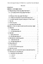
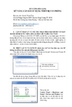
Figures 2-1 and 2-2 illustrate the analysis and design processes, respectively. Analysis proceeds in a generally unidirectional
flow from given data to final answer with the aid of certain analytical tools. Design, however, is an iterative process. Although there
are certain “givens” to start with, they are often not immutable but
AIR-CONDITIONING SYSTEM DESIGN MANUAL⏐11
Figure 2-1. Diagram illustrating analysis.
subject to modification during the design process. For example, an
owner or architect may be confronted with the energy implications
of excessively large expanses of glass that had been originally specified and may decide to reduce the area of glazing or change the
glazing properties. The mechanical designer may try various system components and control strategies before finding one that best
suits the particular context and conditions. Thus, design consists of
a continuous back-and-forth process as the designer selects from a
universe of available systems, components, and control options to
synthesize an optimum solution within the given constraints. This
iterative design procedure incorporates analysis. Analysis is an
important part of any design.
Since the first step in design is to map out the general boundaries within which solutions are to be found, it may be hard to know
where and how to start because there is no background from which
to make initial assumptions. To overcome this obstacle, make
informed initial assumptions and improve on them through subsequent analysis. To assist you in making such initial assumptions,
simple rules are given throughout the chapters in this manual, and
illustrative examples are provided in the appendices.
2.3 DESIGN PHASES
A new engineer must understand how buildings are designed.
Construction documents (working drawings and specifications)
12⏐ THE DESIGN PROCESS
Figure 2-2. Diagram illustrating design.
for a building are developed as a team effort. The architect usually
acts as the prime design professional and project coordinator,
although experienced owners and developers may deal directly
with pre-selected HVAC&R consultants. The architect interfaces
with the owner, directs the architectural staff, and coordinates the
work of outside or in-house mechanical, electrical, and structural
engineers (among other consultants). The negotiated design fees
for the consultants’ work establish an economically viable level of
effort. This fiscal constraint usually seriously limits the amount of
time that can be allocated to studies of alternative systems or
innovative approaches.
The project phases outlined below are those adopted by
ASHRAE Guideline 0-2005 and are those generally recognized by
the architecture profession. More explicit phases may be defined for
certain projects or under certain contracts.
AIR-CONDITIONING SYSTEM DESIGN MANUAL⏐13
2.3.1 Predesign Phase
Before a mechanical engineer can design an HVAC system, a
building program must be created. This is usually prepared by the
client or his/her consultants. The program establishes space needs
and develops a project budget. The building program should
include, but need not be limited to, the following:
•
•
•
•
•
•
•
•
•
The client’s objectives and strategies for the initial and
future functional use of the building, whether it be a singleor multiple-family dwelling or a commercial, industrial, athletic, or other facility.
A clear description of function(s) for each discrete area within
the building.
The number, distribution, and usage patterns of permanent
occupants and visitors.
The type, distribution, and usage patterns of owner-provided
heat-producing equipment.
The geographic site location, access means, and applicable
building and zoning codes.
The proposed building area, height, number of stories, and
mechanized circulation requirements.
The owner’s capital cost and operating cost budgets.
A clear statement of anticipated project schedule and/or time
constraints.
A clear statement of required or expected project quality.
Although some of this information may not be available before
the mechanical designer starts to work, it must be obtained as soon
as possible to ensure that only those HVAC&R systems that are
compatible with the building program are considered.
While the architect prepares the general building program, the
mechanical engineer has the responsibility of developing a discipline-specific program even though some of this information may
be provided by the architect or owner. The building program and
use profile provided by the owner or architect and the HVAC&R
systems program developed by the engineer in response to the
building functional program should be explicitly documented for
future reference. This documentation is termed the Owner’s Project
Requirements (OPR) by ASHRAE Guideline 0-2005, and it provides the context for all design decisions. All changes made to the
program during the design process should be recorded so that the
documentation is always up-to-date.
14⏐ THE DESIGN PROCESS
The information that should be contained in the HVAC&R system program includes
•
•
•
•
•
design outdoor dry-bulb and wet-bulb temperatures (absolute
and coincident);
heating and cooling degree-days/hours;
design wind velocity (and direction) for winter and summer;
applicable zoning, building, mechanical, fire, and energy
codes; and
rate structure, capacity, and characteristics of available utilities
and fuels.
Additional information regarding solar radiation availability
and subsurface conditions would be included if use of a solar thermal system or ground-source heat pump was anticipated.
The environmental conditions to be maintained for each building space should be defined by
•
•
•
•
dry-bulb and wet-bulb temperatures during daytime occupied
hours, nighttime occupied hours, and unoccupied hours;
ventilation and indoor air quality requirements;
any special conditions, such as heavy internal equipment loads,
unusual lighting requirements, noise- and-vibration-free areas,
humidity limits, and redundancy for life safety and security; and
acceptable range of conditions for each of the above.
An understanding of the functional use for each area is essential to select appropriate HVAC&R systems and suitable control
approaches because the capabilities of proposed systems must be
evaluated and compared to the indoor environmental requirements.
For example, if some rooms in a building require humidity control
while others do not, the HVAC system must be able to provide
humidification to areas requiring it without detriment to the building enclosure or other spaces. Some areas may require cooling,
while others need only ventilation or heating. This will affect selection of an appropriate system.
2.3.2 Design Phase
In conventional (business-as-usual) building projects, serious
work on HVAC&R system design typically occurs in the later
stages of the design phase. Projects where energy efficiency and/or
green building design are part of the intent or building types where
HVAC&R systems are absolutely integral to building design (labo-
AIR-CONDITIONING SYSTEM DESIGN MANUAL⏐15
ratories, hospitals, etc.), will see HVAC&R design begin earlier and
play a more integrated role in design decision making.
The design phase is often broken down into three subphases:
conceptual design, schematic design, and design development. The
terms schematic design, design development, and construction
documents are also commonly used to describe design process subphases. The purpose of conceptual/schematic design efforts is to
develop an outline solution to the OPR that captures the owner’s
attention, gets his/her buy-in for further design efforts, and meets
budget. Schematic (or early design development) design efforts
should serve as proof of concept for the earliest design ideas as
elements of the solution are further developed and locked into
place. During later design development/construction documents,
the final drawings and specifications are prepared as all design
decisions are finalized and a complete analysis of system performance is undertaken.
The schematic/early design development stage should involve
the preliminary selection and comparison of appropriate HVAC&R
systems. All proposed systems must be able to maintain the environmental conditions for each space as defined in the OPR. The
ability to provide adequate thermal zoning is a critical aspect of
such capability. For each system considered during this phase, evaluate the relative space (and volume) requirements for equipment,
ducts, and piping; fuel and/or electrical use and thermal storage
requirements; initial and life-cycle costs; acoustical requirements
and capabilities; compatibility with the building plan and the structural system; and the effects on indoor air quality, illumination, and
aesthetics. Also consider energy code compliance and green design
implications (as appropriate).
Early in the design phase, the HVAC&R designer may be asked
to provide an evaluation of the impact of building envelope design
options (vis-à-vis energy code compliance and trade-offs and/or
green building intents), heavy lighting loads (i.e., more than 2 W/ft2
[22 W/m2]), and other unusual internal loads (i.e., more than 4 W/ft2
[43 W/m2]) on HVAC system performance and requirements. Questions should also be expected regarding the optimum location of
major mechanical equipment—considering spatial efficiency, system effectiveness, aesthetics, and acoustical criteria. Depending
upon the level of information available, the designer may be asked to
prepare preliminary HVAC system sizing or performance estimates
based upon patterns developed through experience or based upon
results from similar, previously designed projects. Some design esti-
16⏐ THE DESIGN PROCESS
mates that may be useful for a first cut are given in Table 2-1. Additional values appropriate for this design phase can be found in the
ASHRAE Pocket Guide for Air Conditioning, Heating, Ventilation,
Refrigeration (ASHRAE 2005c).
If envelope and internal loads are reasonably well defined,
peak load and rough energy calculations for alternative HVAC systems may be prepared at this time using appropriate methods for
presentation to the architect and/or owner. Although they are preliminary and will change as the building design proceeds, such preliminary loads are usually definitive enough to compare the
performance of alternative systems because these systems will be
sized to meet the same loads. As you gain experience, you will be
able to estimate the likely magnitude of the loads for each area in a
building with a little calculation effort.
Resources useful during this phase of design include design
manuals, textbooks, equipment literature, and data from existing
installations. Frequently, this type of early system evaluation
eliminates all but a few systems that are capable of providing the
environmental requirements and are compatible with the building structure.
If the client requests it, if architectural details have been sufficiently developed, and if the mechanical engineer’s fee has been set
at a level to warrant it, comparisons between construction (first)
costs and operating (life-cycle) costs and the performance of different HVAC&R systems can be made in greater detail. Typically, one
system is set as a reference (or base) and other proposed systems
are compared to this base system. Such an analysis would proceed
according to the following steps:
1. Estimate the probable capital costs of each system using unit
area allowances, a rough selection of equipment, sketches of
system layouts, and such tools as:
• Cost-estimating manuals
• Recently completed similar projects (many technical journals contain case studies that provide such information)
• Local HVAC&R contractors
• Professional cost estimators
• Design office files
• Experienced design engineers.
2. Identify the energy source or sources available and their cost
per a convenient unit of energy (million Btu, kWh, therm), considering both present and anticipated costs. Determine local
AIR-CONDITIONING SYSTEM DESIGN MANUAL⏐17
Table 2-1. Selected Load and
Airflow Estimates for Schematic Design
General:
Offices:
High-Rise
Apartment Buildings:
Hospitals:
Shopping Centers:
Hotels:
Restaurants:
Central Plants:
Urban districts
College campuses
Commercial centers
Residential centers
450 ± 100 ft2/ton for cooling loads
[12 ± 3 m2/kW]
1.5 cfm/ft2 air supply—
exterior spaces
[7.6 L/s per m2]
0.75 cfm/ft2 air supply—
interior spaces (minimum)
[3.8 L/s per m2]
400 cfm/ton air supply
for all-air systems
[54 L/s per kW]
500 ft2/ton [13 m2/kW]
based upon:
lights—1.5 W/ft2 [16 W/m2]
fans—0.75 W/ft2 [8 W/m2]
pumps—0.25 W/ft2 [2.7 W/m2]
miscellaneous electrical—
2.0 W/ft2 [21 W/m2]
occupancy—150 ft2/person
[14 m2/person]
1000 ft2/ton for north-facing
apartments [26 m2/kW]
500 ft2/ton [13 m2/kW] for others
333 ft2/ton based upon
1000 ft2/bed
[8.7 m2/kW at 93 m2/bed]
average—400 ft2/ton
[10.4 m2/kW]
department stores—2 W/ft2
[21 W/m2]
specialty stores—5 W/ft2
[54 W/m2]
350 ft2/ton [9.1 m2/kW]
150 ft2/ton [3.9 m2/kW]
380 ft2/ton [9.9 m2/kW]
320 ft2/ton [8.3 m2/kW]
475 ft2/ton [12.4 m2/kW]
500 ft2/ton [13 m2/kW]
- Xem thêm -