Progress In Electromagnetics Research, Vol. 140, 31–42, 2013
AN APPROACH FOR MULTI-BAND BANDPASS
FILTER DESIGN BASED ON ASYMMETRIC
HALF-WAVELENGTH RESONATORS
Xiuping Li1, 2, * and Huisheng Wang1, 2
1 School
of Electronic Engineering, Beijing University of Posts and
Telecommunications, Beijing 100876, China
2 Beijing
Key Laboratory of Work Safety Intelligent Monitoring, Beijing
University of Posts and Telecommunications, Beijing 100876, China
Abstract—This paper presents that the extra passband with two
transmission zeros can be obtained by adding shunt open stubs to
the asymmetric half-wavelength resonators structure. By using this
method, a fourth or even higher passband with good selectivity and
compact size can be obtained. Dual-band, tri-band and quad-band
bandpass filters are demonstrated by using this method. The measured
bandwidth is 80/180 MHz for the dual-band, 60/180/180 MHz for
the tri-band and 130/360/170/70 MHz for the quad-band filter,
respectively. The measured insertion loss for the dual-band, tri-band
and quad-band filter is less than 2.7 dB, 2.5 dB and 2.9 dB at the center
frequency. All the simulated results and the measured results agree
well.
1. INTRODUCTION
Recent development in wireless communication and radar systems
has presented new challenges to design and produce high-quality
miniature components with multi-band performance. There are
many methods to design multi-band filters, such as combining two
single-band filters at different passband frequencies [1–5], adding
defected stepped impedance resonator (DSIR) and microstrip stepped
impedance resonator (MSIR) [6–9] or adding a couple of resonators [10–
13]. The method of adding shunt open stub to the center of the
resonator is used to design dual-band filter and there are three
transmission zeros for the two passbands [14, 15]. The combination
Received 15 March 2013, Accepted 23 April 2013, Scheduled 22 May 2013
* Corresponding author: Xiuping Li (
[email protected]).
32
Li and Wang
of adding shunt open stub to the center of the resonator and adding
resonators is used to design tri-band filter, where five transmission
zeros for the three passbands [16–18].
This paper presents the applications of shunt open stubs for
microstrip multi-band bandpass filter design. Theoretical analysis on
obtaining multi-passband performance by adding shunt open stubs to
the asymmetric half-wavelength resonators is introduced. By using
this method, the fourth even higher passband can be obtained by
adding shunt open stubs and the filter dimension is kept compact.
Furthermore, in order to verify the method, the dual-band, tri-band
and quad-band filters are fabricated and the expected responses are
obtained. The simulated results and the measured results agree well.
The rest of the paper is organized as follows: the theoretical
analysis with ABCD matrix method is given to explain the new
approach in Section 2. In Section 3, the dual-band, tri-band and quadband filters are fabricated to verify the method. The conclusion is given
in Section 4.
2. ANALYSIS OF THE ASYMMETRIC HALF-WAVELENGTH RESONATORS WITH SHUNT OPEN STUBS
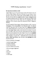
In order to facilitate the analysis, the asymmetric half-wavelength
resonators coupling structure with shunt open stub is design, as shown
in Fig. 1. The total length of one resonator is 2l3 + l2 + l1 = λ0 = 2,
where λ0 is the guided wavelength at fundamental resonance. The l4
is the shunt open stub ,which is connected to the resonator directly.
The coupling between the two open ends of the resonators is simply
expressed by the gap capacitance CS [19, 20].
Inspecting the Fig. 1, the whole circuit represents a shunt circuit,
l 3 Upper l 3
l1
l2
CS
l4
l4
Output
Input
l4
S
l4
l1
l2
l3
Lower l 3
Figure 1. Configuration of asymmetric half-wavelength resonators
coupling structure with shunt open stubs (l1 > l2 ).
Progress In Electromagnetics Research, Vol. 140, 2013
33
as the dotted boxes shows, which consists of upper and lower sections.
Each section is composed of l1 , l2 , l3 , l4 and CS . The ABCD matrices
for the upper and lower sections of the lossless shunt circuit are
·
¸
A B
= M1 M4 M3 MC M3 M4 M2
(1a)
C D upper
·
¸
A B
= M2 M4 M3 MC M3 M4 M1
(1b)
C D lower
with
¸
cos βln
jZ0 sin βln
(n = 1, 2, 3)
jY0 sin βln
cos βln
·
¸
·
¸
1
1 jωC
1
0
S
MC =
M4 =
jY0 tan βl4 1
0
1
·
Mn =
where β is the propagation constant, Z0 the characteristic impedance
of the resonator, ω the angular frequency, and Y0 = 1/Z0 . The
Y -parameters for this circuit can be obtained by adding the upper
and the lower section Y -parameters, which follow from (1a) and (1b),
respectively. When the load is matching, S21 of the circuit can then be
calculated from the total Y -parameters. The S21 for the whole circuit
are
S21 =
4Y0 B
Y02 B 2 +Y0 B (A1 +A2 +D1 +D2 )+4BC +D1 A2 +D2 A1 −D1 A1 −D2 A2
(2)
with
A1=D2 = cos β (l1 + l2 + 2l3 ) − cos β (l2 + 2l3 ) sin βl1 tan βl4
−sin β (l1 +2l3 ) cosβl2 tanβl4 +sin βl1 cos βl2 sin 2βl3 tan βl42
Y0
+
[cos β (l1 + l3 ) sin β (l2 + l3 )
ωCs
− sin β (l2 + l3 ) sin βl1 cos βl3 tan βl4
+ cos β (l1 +l3 ) cos βl2 cos βl3 tan βl4
− sin βl1 cos βl2 cos βl32 tan βl42 ]
D1=A2 = cos β (l1 + l2 + 2l3 ) − cos β (l1 + 2l3 ) sin βl2 tan βl4
−sin β (l2 +2l3 ) cosβl1 tan βl4 +cos βl1 sin βl2 sin 2βl3 tan βl42
Y0
+
[sin β (l1 + l3 ) cos β (l2 + l3 )
ωCs
− sin β (l1 + l3 ) sin βl2 cos βl3 tan βl4
+ cos β (l2 + l3 ) cos βl1 cos βl3 tan βl4
¤
− cos βl1 sin βl2 cos βl32 tan βl42
34
Li and Wang
B1=B2 = jZ0 [sin β (l1 + l2 + 2l3 ) − sin β (l1 + 2l3 ) sin βl2 tan βl4
¤
−sin β (l2 +2l3 ) sinβl1 tan βl4 +sin βl1 sin βl2 sin2βl3 tanβl42
1
+
[cos β (l1 + l3 ) cos β (l2 + l3 )
jωCs
− cos β (l1 + l3 ) sin βl2 cos βl3 tan βl4
− cos β (l2 + l3 ) sin βl1 cos βl3 tan βl4
¤
+ sin βl1 sin βl2 cos βl32 tan βl42
C1=C2 = jY0 [sin β (l1 + l2 + 2l3 ) + cos β (l1 + 2l3 ) cos βl2 tan βl4
¤
+cos β(l2 +2l3 ) cosβl1 tanβl4 −cosβl1 cos βl2 sin 2βl3 tanβl42
jY02
[sin β (l1 + l3 ) sin β (l2 + l3 )
ωCs
+ sin β (l1 + l3 ) cos βl2 cos βl3 tan βl4
+ sin β (l2 + l3 ) cos βl1 cos βl3 tan βl4
+ cos βl1 cos βl2 cos βl32 tan βl42 ]
the transmission zeros can be found by letting S21 =0. For a small CS ,
an approximate equation can be obtained as:
cos β(l2 +l3 ) cos β(l1 +l3 ) − cos β(l2 + l3 ) sin βl1 cos βl3 tan βl4
−cos β(l1 +l3 ) sin βl2 cosβl3 tan βl4 +sin βl1 sinβl2 cosβl32 tanβl42 = 0 (3)
further, Equation (3) can be expressed as:
[cos β(l1 + l3 ) − sin βl1 cos βl3 tan βl4 ]
×[cos β(l2 + l3 ) − sin βl2 cos βl3 tan βl4 ] = 0
Generally, we assume l1 < λ0 /4, l2 < λ0 /4, l3 < λ0 /4, l4 < λ0 /4,
where λ0 is the guided wavelength at fundamental resonance. Thus,
we can obtain sin βl1 cos βl3 tan βl4 > 0 and sin βl2 cos βl3 tan βl4 >
0. In addition, we assume sin βl1 cos βl3 tan βl4 < 1 and
sin βl2 cos βl3 tan βl4 < 1. The two transmission zeros, f1 and f2 can
be obtained as:
c × n × arccos(sin βl1 cos βl3 tan βl4 )
f1 =
(4a)
√
2π εeff (l1 + l3 )
+
f2 =
c × n × arccos(sin βl2 cos βl3 tan βl4 )
√
2π εeff (l2 + l3 )
(4b)
where εeff is the effective dielectric constant, n is the mode number, c
is the speed of light in free space. After transformation, Equation (2)
also can be expressed as:
[cos β(l1 + l3 + l4 ) + cos βl1 sin βl3 sin βl4 ]
×[cos β(l2 + l3 + l4 ) + cos βl2 sin βl3 sin βl4 ] = 0
Progress In Electromagnetics Research, Vol. 140, 2013
35
and thus the other two transmission zeros, f3 and f4 , can be obtained
as:
c × n × arccos(− cos βl2 sin βl3 sin βl4 )
f3 =
(5a)
√
2π εeff (l1 + l3 + l4 )
f4 =
c × n × arccos(− cos βl1 sin βl3 sin βl4 )
√
2π εeff (l2 + l3 + l4 )
(5b)
Equations (4) and (5) present the transmission zeros on the both
sides of the first and second passband, respectively.
3. APPLICATIONS
Based on the above analysis, the dual-band, tri-band and quad-band
passband filters are designed and fabricated. A commercial TLX-0
dielectric substrate of TACONIC with the relative dielectric constant
of 2.45 and thickness of 0.79 mm is chosen to fabricate the filters and
Agilent’s N 5071c network analyzer is used for measurement.
3.1. Dual-band Filter Design
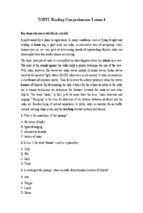
The filter with shunt open stubs is designed and fabricated, as shown
in Fig. 2. The asymmetric half-wavelength resonators filter without
shunt open stubs is illustrated in Fig. 2(a). Figs. 2(b) and Fig. 2(c)
show the filter with four and eight shunt open stubs.
As shown in Fig. 3, the center frequency of the filter is shifted from
2.4 GHz to 2.1 GHz. Meanwhile, the two transmission zeros on the
7.9
2
2
12.5
2.2
0.8
10
6
2
Unit: mm
(a)
(b)
(c)
Figure 2. The photograph and size of the filters. (a) Filter without
shunt open stubs. (b) Filter with four shun open stubs. (c) Filter with
eight shunt open stubs.
36
Li and Wang
both side of the first passband change from (2.16, 2.76) GHz to (1.92,
2.51) GHz by adding four shunt open stubs. It was also observed, after
adding four shunt open stubs, an extra passband appeared at 6 GHz.
Its corresponding transmission zeros on the both sides of the passband
are (5.78, 6.18) GHz. The center frequency and bandwidth are 6 GHz
and 270 MHz, respectively.
As shown in Fig. 3, the insertion loss of the passband is not good at
6 GHz and the return loss is worse than −10 dB. The reason is caused
by the second harmonic of the fundamental passband, which locates
too close to the new passband. To suppress the second harmonic
of the fundamental passband, another four shunt short stubs are
added [21, 22], as shown in Fig. 2(c). By using this method, the second
harmonic can be weaken and shifted toward lower frequency.
As shown in Fig. 4, the center frequency of the first passband
Figure 3. The responses of the filter without and with four shunt
open stubs.
Figure 4. The responses of the filter with eight shunt open stubs.
Progress In Electromagnetics Research, Vol. 140, 2013
37
is shifted toward lower frequency to 1.9 GHz and its bandwidth is
40 MHz. Meanwhile, the center frequency and bandwidth of the second
passband are 5.8 GHz and 100 MHz, respectively. Moreover, in the
passband, both the return loss and insertion loss are better than
−10 dB and −2.7 dB, respectively.
3.2. Tri-band Filter Design
As above-mentioned, a passband with two transmission zeros can be
obtained by shunt open stubs. We use this method to achieve the third
passband by adding shunt open stubs. Fig. 5 shows the comparing of
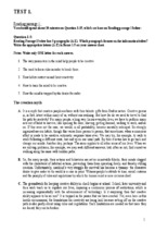
the tri-band filter with and without new shunt open stubs.
In Fig. 5, without new shunt open stubs, there are two passbands
with the center frequency of 2.08 GHz and 6.04 GHz and there are the
transmission zeros at 1.84 GHz, 2.39 GHz, 5.8 GHz and 6.32 GHz. New
passband at 4.03 GHz is introduced by adding new shunt open stubs
and the center frequencies of the two passbands are shifted to 1.57 GHz
0
0
-5
New passband
-10
S 21 (dB)
-20
-15
-30
-20
-25
-40
S 11 (dB)
-10
-30
With new shunt open stubs
Without new shunt open stubs
-50
-60
0.5
1.5
2.5
3.5
4.5
Frequency (GHz)
5.5
6.5
-35
-40
7.5
Figure 5. The comparison of the tri-band filter with and without new
shunt open stubs.
Figure 6. The photograph of tri-band filter.
38
Li and Wang
and 6.29 GHz. The photograph of the tri-band filter is shown in Fig. 6.
Obviously, comparing with the filter in Fig. 2(c), there are another four
new shunt open stubs is added,which is folded for miniaturization.
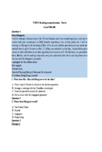
The responses of the tri-band filter are illustrated in Fig. 7. The
measured −3 dB frequency ranges (fractional bandwidths) for the three
passbands centered at 1.51, 4, and 6.26 GHz are 1.484–1.546 GHz
(4.1%), 3.9–4.0 GHz (3.4%) and 6.19–6.34 GHz (2.3%), respectively.
The minimum insertion losses measured for these three passbands are
−2.5, −1.6, and −2.5 dB. The obtained transmission zeros from shunt
open stubs are 1.385 and 1.685 GHz for the first passband, 3.810 and
4.224 GHz for the second band, and 6.104 and 6.481 GHz for the third
band.
0
0
S 21
S 11
-10
S 21 (dB)
-30
-20
-40
-50
Measured
Simulated
-30
6
-40
7
-60
-70
1
2
3
4
Frequency (GHz)
5
Figure 7. The responses of the tri-band filter.
Figure 8. The photograph of quad-band filter.
S11 (dB)
-10
-20
Progress In Electromagnetics Research, Vol. 140, 2013
39
3.3. Quad-band Filter Design
The photograph of the quad-band filter is illustrated in Fig. 8, and
Fig. 9 shows the quad-band filter with and without new shunt open
stubs. Without new shunt open stubs, there are three passbands with
the center frequency of 1.51 GHz, 3.95 GHz and 6.47 GHz and there
are transmission zeros at 1.26 GHz, 1.80 GHz, 3.69 GHz, 4.39 GHz,
6.09 GHz and 6.74 GHz. New passband at 7.13 GHz is introduced
by adding new shunt open stubs and the center frequency of the
three passbands are shifted to 1.37 GHz, 3.94 GHz and 6.09 GHz.
The response of the quad-band filter is shown in Fig. 10. The
measured −3 dB frequency ranges (fractional bandwidths) for the
four passbands centered at 1.37, 3.9, 6.07 and 7.11 GHz are 1.29–
1.42 GHz (9.5%), 3.72–4.08 GHz (9.2%), 5.96–6.13 GHz (2.8%) and
7.06–7.13 GHz (0.9%), respectively. The minimum insertion losses
S21 (dB)
-10
-10
-20
-20
-30
-30
S11 (dB)
0
0
-40
-40
New passband
-50
-50
-60
0.5
Without new shunt open stubs
With new shunt open stubs
1.5
2.5
3.5
4.5
5.5
Frequency (GHz)
6.5
7.5
-60
Figure 9. The comparison of the quad-band filter with and without
new shunt open stubs.
S 21 (dB)
-10
-10
-20
-20
-30
-30
Simulared
Measured
-40
-50
1
2
3
4
5
Frequency (GHz)
-40
6
7
Figure 10. The responses of the quad-band filter.
8
-50
S11 (dB)
0
0
40
Li and Wang
measured for the four passbands are −1.2, −1.1, −2.3 and −2.9 dB.
The transmission zeros from shunt open stubs are 1.17 and 1.63 GHz
for the first passband, 3.65 and 4.37 GHz for the second band, 5.89
and 6.26 GHz for the third band and 6.95 and 7.28 GHz for the fourth
band.
4. CONCLUSION
In this letter, a method to design multi-band filter is proposed and
demonstrated, which is implemented by adding shunt open stubs to
asymmetric half-wavelength resonators structure. The shunt open
stubs can generate the second, third and forth passbands, while
keeping the half-wavelength resonator as the first passband. The center
frequencies of the passbands can be independently controlled by the
length of the shunt open stubs and the half-wavelength resonator. To
verify the method, the dual-band, tri-band and quad-band filters are
fabricated and the expected responses are obtained. The simulated
results and the measured results agree well.
ACKNOWLEDGMENT
This work was supported by National Natural Science Foundation of
China (No. 61072009) and the support from Fundamental Research
Funds for the Central Universities.
REFERENCES
1. Chen, C.-Y. and C.-Y. Hsu, “A simple and effective method
for microstrip dual-band filters design,” IEEE Microw. Wireless
Compon. Lett., Vol. 16, No. 5, 246–248, May 2006.
2. Chen, C.-Y. and C.-Y. Hsu, “A simple and effective method
for microstrip dual-band filters design” IEEE Microw. Wireless
Compon. Lett., Vol. 16, No. 5, 246–248, May 2006.
3. Wu, G.-L., W. Mu, X.-W. Dai, and Y.-C. Jiao, “Design of novel
dual-band bandpass filter with microstrip meander-loop resonator
and CSRR DGS,” Progress In Electromagnetics Research, Vol. 78,
17–24, 2008.
4. Zhao, L.-P., X.-W. Dai, Z.-X. Chen, and C.-H. Liang, “Novel
design of dual-mode dual-band bandpass filter with triangular
resonators,” Progress In Electromagnetics Research, Vol. 77, 417–
424, 2007.
Progress In Electromagnetics Research, Vol. 140, 2013
41
5. Chen, C.-Y. and C.-C. Lin, “The design and fabrication of a
highly compact microstrip dual-band bandpass filter,” Progress
In Electromagnetics Research, Vol. 112, 299–307, 2011.
6. Wu, B., C.-H. Liang, Q. Li, and P.-Y. Qin, “Novel dual-band filter
incorporating defected SIR and microstrip SIR,” IEEE Microw.
Wireless Compon. Lett., Vol. 18, No. 6, 392–394, June 2008.
7. Chiou, Y.-C. and J.-T. Kuo, “Planar multiband bandpass filter
with multimode stepped-impedance resonators,” Progress In
Electromagnetics Research, Vol. 114, 129–144, 2011.
8. Chen, W.-Y., M.-H. Weng, S.-J. Chang, H. Kuan, and Y.H. Su, “A new tri-band bandpass filter for GSM, WiMAX and
ultra-wideband responses by using asymmetric stepped impedance
resonators,” Progress In Electromagnetics Research, Vol. 124, 365–
381, 2012.
9. Ma, D., Z. Y. Xiao, L. Xiang, X. Wu, C. Huang, and X. Kou,
“Compact dual-band bandpass filter using folded SIR with
two stubs for WLAN,” Progress In Electromagnetics Research,
Vol. 117, 357–364, 2011.
10. Lee, S.-Y. and C.-M. Tsai, “New cross-coupled filter design using
improved hairpin resonators,” IEEE Trans. Microwave Theory
Tech., Vol. 48, No. 12, 2482–2490, February 2000.
11. Zhang, X. Y., C. H. Chan, Q. Xue, and B.-J. Hu, “Dual-band
bandpass filter with controllable bandwidths using two coupling
paths,” IEEE Microw. Wireless Compon. Lett., Vol. 20, No. 11,
616–618, June 2010.
12. Zhu, Y.-Z. and Y.-J. Xie, “Novel microstrip bandpass filters
with transmission zeros,” Progress In Electromagnetics Research,
Vol. 77, 29–41, 2007.
13. Kuo, J.-T. and S.-W. Lai,“New dual-band bandpass filter
with wide upper rejection band,” Progress In Electromagnetics
Research, Vol. 123, 371–384, 2012.
14. Doan, M. T., W. Che, K. Deng, and W. Feng, “Compact triband bandpass filter using stub-loaded resonator and quarterwavelength resonator,” 2011 China-Japan Joint Microwave
Conference Proceedings (CJMW), 1–4,, April 2011.
15. Zhang, X. Y., J.-X. Chen, Q. Xue, and S.-M. Li, “Dual-band
bandpass filters using stub-loaded resonators,” IEEE Microw.
Wireless Compon. Lett., Vol. 17, No. 8, 583–585, June 2007.
16. Zhang, X. Y., Q. Xue, and B. J. Hu, “Planar tri-band bandpass
filter with compact size,” IEEE Microw. Wireless Compon. Lett.,
Vol. 20, No. 5, 262–264, June 2010.
42
Li and Wang
17. Chu, Q.-X., F.-C. Chen, Z.-H. Tu, and H. Wang, “A novel crossed
resonator and its applications to bandpass filters,” IEEE Trans.
Microwave Theory Tech., Vol. 57, No. 7, 1753–1759, July 2009.
18. Yang, C.-F., Y.-C. Chen, C.-Y. Kung, J.-J. Lin, and T.-P. Sun,
“Design and fabrication of a compact quad-band bandpass filter
using two different parallel positioned resonators,” Progress In
Electromagnetics Research, Vol. 115, 159–172, 2011.
19. Kwok, R. S. and J. F. Liang, “Characterization of highQ resonators for microwave-filter applications,” IEEE Trans.
Microwave Theory Tech., Vol. 47, No. 1, 111–114, January 1999.
20. Gupta, K. C., R. Garg, I. Bahl, and P. Bhartia, Microstrip Lines
and Slotlines, 2nd Edition, Artech House, Boston, MA, 1996.
21. Zhang, J., J.-Z. Gu, B. Cui, and X.-W. Sun, “Compact and
harmonic suppression open-loop resonator bandpass filter with
tri-section SIR,” Progress In Electromagnetics Research, Vol. 69,
93–100, 2007.
22. Wu, H.-W., S.-K. Liu, M.-H. Weng, and C.-H. Hung, “Compact
microstrip bandpass filter with multispurious suppression,”
Progress In Electromagnetics Research, Vol. 107, 21–30, 2010.