Hướng dẫn sử dụng máy thở Aestiva_user_manual_part1
Aestiva/5
Operation Manual - Part 1
Software Revision 4.X
System Controls, Operation, Checkout
User Responsibility
This Product will perform in conformity with the description thereof contained
in this Operation manual and accompanying labels and/or inserts, when
assembled, operated, maintained, and repaired in accordance with the
instructions provided. This Product must be checked periodically. A defective
Product should not be used. Parts that are broken, missing, plainly worn,
distorted, or contaminated should be replaced immediately. Should repair or
replacement become necessary, Datex-Ohmeda recommends that a
telephonic or written request for service advice be made to the nearest
Datex-Ohmeda Customer Service Center. This Product or any of its parts
should not be repaired other than in accordance with written instructions
provided by Datex-Ohmeda and by Datex-Ohmeda trained personnel. The
Product must not be altered without the prior written approval of
Datex-Ohmeda. The user of this Product shall have the sole responsibility for
any malfunction which results from improper use, faulty maintenance,
improper repair, damage, or alteration by anyone other than Datex-Ohmeda.
w CAUTION
U.S. Federal law restricts this device to sale by or on the order of a
licensed medical practitioner. Outside the U.S.A., check local
laws for any restriction that may apply.
Datex-Ohmeda products have unit serial numbers with coded logic which
indicates a product group code, the year of manufacture, and a sequential
unit number for identification.
AAA F 12345
This alpha character indicates the year of product
manufacture and when the serial number was
assigned; “D” = 2000, “E” = 2001, “F” = 2002, etc.
“I” and “O” are not used.
Aestiva, S/5, PSVPro, Tec 5, Tec 6 and Tec 7 are registered trademarks of
Datex-Ohmeda Inc.
Other brand names or product names used in this manual are trademarks or
registered trademarks of their respective holders.
Table of Contents
1/Introduction
i
How to use this manual . . . . . . . . . . . . . . . . . . . . . . . . . . . . . . . . . . . . . . . . . 1-2
What is an Aestiva? . . . . . . . . . . . . . . . . . . . . . . . . . . . . . . . . . . . . . . . . . . . . 1-2
Ventilators and monitors . . . . . . . . . . . . . . . . . . . . . . . . . . . . . . . . . . . . 1-3
Symbols used in the manual or on the equipment . . . . . . . . . . . . . . . . . . . . 1-5
2/System Controls and Menus
Anesthesia system controls . . . . . . . . . . . . . . . . . . . . . . . . . . . . . . . . . . . . . . 2-2
Breathing system controls. . . . . . . . . . . . . . . . . . . . . . . . . . . . . . . . . . . . . . . . 2-5
Vaporizer controls . . . . . . . . . . . . . . . . . . . . . . . . . . . . . . . . . . . . . . . . . . . . . . 2-9
Ventilator controls . . . . . . . . . . . . . . . . . . . . . . . . . . . . . . . . . . . . . . . . . . . . .2-11
Optional features . . . . . . . . . . . . . . . . . . . . . . . . . . . . . . . . . . . . . . . . . .2-11
Control panel . . . . . . . . . . . . . . . . . . . . . . . . . . . . . . . . . . . . . . . . . . . . .2-11
How to set controls. . . . . . . . . . . . . . . . . . . . . . . . . . . . . . . . . . . . . . . . .2-14
How to use the menu . . . . . . . . . . . . . . . . . . . . . . . . . . . . . . . . . . . . . . .2-15
Menu map . . . . . . . . . . . . . . . . . . . . . . . . . . . . . . . . . . . . . . . . . . . . . . .2-16
More about menu functions . . . . . . . . . . . . . . . . . . . . . . . . . . . . . . . . .2-17
How to change menu settings . . . . . . . . . . . . . . . . . . . . . . . . . . . . . . . .2-18
Optional flowmeter and suction regulators . . . . . . . . . . . . . . . . . . . . . . . . .2-19
Suction regulator controls . . . . . . . . . . . . . . . . . . . . . . . . . . . . . . . . . . .2-20
External flowmeter controls . . . . . . . . . . . . . . . . . . . . . . . . . . . . . . . . . .2-20
Optional CO2 Bypass mode operation . . . . . . . . . . . . . . . . . . . . . . . . . . . . .2-21
3/Operation and Tutorial
Turn On the system . . . . . . . . . . . . . . . . . . . . . . . . . . . . . . . . . . . . . . . . . . . . . 3-2
Set the alarm loudness . . . . . . . . . . . . . . . . . . . . . . . . . . . . . . . . . . . . . . . . . . 3-3
Show or hide alarm limits and units . . . . . . . . . . . . . . . . . . . . . . . . . . . . . . . . 3-5
Adjust patient data for Heliox . . . . . . . . . . . . . . . . . . . . . . . . . . . . . . . . . . . . . 3-7
Turn the volume alarms on or off . . . . . . . . . . . . . . . . . . . . . . . . . . . . . . . . . . 3-8
Set alarm limits . . . . . . . . . . . . . . . . . . . . . . . . . . . . . . . . . . . . . . . . . . . . . . . . 3-9
Set an audible alarm for circuit leaks . . . . . . . . . . . . . . . . . . . . . . . . . . . . .3-11
Set Cardiac Bypass . . . . . . . . . . . . . . . . . . . . . . . . . . . . . . . . . . . . . . . . . . . .3-12
1006-0938-000
i
Aestiva
Start mechanical ventilation . . . . . . . . . . . . . . . . . . . . . . . . . . . . . . . . . . . . 3-14
ii
Stop mechanical ventilation . . . . . . . . . . . . . . . . . . . . . . . . . . . . . . . . . . . . 3-15
Set the ventilation mode . . . . . . . . . . . . . . . . . . . . . . . . . . . . . . . . . . . . . . . 3-16
Set ventilator controls . . . . . . . . . . . . . . . . . . . . . . . . . . . . . . . . . . . . . . . . . 3-18
Optional features . . . . . . . . . . . . . . . . . . . . . . . . . . . . . . . . . . . . . . . . . 3-18
Ventilator controls. . . . . . . . . . . . . . . . . . . . . . . . . . . . . . . . . . . . . . . . . 3-19
Volume Control mode. . . . . . . . . . . . . . . . . . . . . . . . . . . . . . . . . . . . . . 3-20
Pressure Control mode. . . . . . . . . . . . . . . . . . . . . . . . . . . . . . . . . . . . . 3-20
SIMV mode . . . . . . . . . . . . . . . . . . . . . . . . . . . . . . . . . . . . . . . . . . . . . . 3-20
PSVPro mode . . . . . . . . . . . . . . . . . . . . . . . . . . . . . . . . . . . . . . . . . . . . 3-21
Set inspiratory pause (volume mode) . . . . . . . . . . . . . . . . . . . . . . . . 3-22
Set SIMV and PSVPro controls . . . . . . . . . . . . . . . . . . . . . . . . . . . . . . . . . . 3-24
Silence alarms . . . . . . . . . . . . . . . . . . . . . . . . . . . . . . . . . . . . . . . . . . . . . . . 3-26
Reading the pressure waveform (Paw) . . . . . . . . . . . . . . . . . . . . . . . . . . . . 3-27
Scales . . . . . . . . . . . . . . . . . . . . . . . . . . . . . . . . . . . . . . . . . . . . . . . . . . 3-27
Measure circuit compliance . . . . . . . . . . . . . . . . . . . . . . . . . . . . . . . . . . . . 3-30
Show the service settings . . . . . . . . . . . . . . . . . . . . . . . . . . . . . . . . . . . . . . 3-31
Optional Passive AGSS operation. . . . . . . . . . . . . . . . . . . . . . . . . . . . . . . . 3-33
Optional Active AGSS operation . . . . . . . . . . . . . . . . . . . . . . . . . . . . . . . . . 3-34
Connecting Active AGSS with a flow indicator . . . . . . . . . . . . . . . . . . 3-35
Connecting Active AGSS without a flow indicator . . . . . . . . . . . . . . . 3-36
4/Preoperative Checklist
Every day before the first patient . . . . . . . . . . . . . . . . . . . . . . . . . . . . . .4-2
Every time a different clinician uses the system . . . . . . . . . . . . . . . . . .4-3
Before every patient . . . . . . . . . . . . . . . . . . . . . . . . . . . . . . . . . . . . . . . . .4-3
Appendix - Preoperative Tests
Test Intervals . . . . . . . . . . . . . . . . . . . . . . . . . . . . . . . . . . . . . . . . . . . . . . . . . .A-2
Every day before the first patient . . . . . . . . . . . . . . . . . . . . . . . . . . . . . . . . . .A-3
Inspect the System . . . . . . . . . . . . . . . . . . . . . . . . . . . . . . . . . . . . . . . . .A-3
Minimize alarms (optional) . . . . . . . . . . . . . . . . . . . . . . . . . . . . . . . . . . .A-5
ii
1006-0938-000
Table of Contents
Pipeline and cylinder tests . . . . . . . . . . . . . . . . . . . . . . . . . . . . . . . . . . . A-5
iii
Flow control tests . . . . . . . . . . . . . . . . . . . . . . . . . . . . . . . . . . . . . . . . . . A-7
Vaporizer back pressure test . . . . . . . . . . . . . . . . . . . . . . . . . . . . . . . . . A-8
Power failure test . . . . . . . . . . . . . . . . . . . . . . . . . . . . . . . . . . . . . . . . . . . A-9
Precase steps . . . . . . . . . . . . . . . . . . . . . . . . . . . . . . . . . . . . . . . . . . . .A-11
Every time a different clinician uses the system . . . . . . . . . . . . . . . . . . . . .A-12
Low-pressure leak test . . . . . . . . . . . . . . . . . . . . . . . . . . . . . . . . . . . . .A-12
Before every patient . . . . . . . . . . . . . . . . . . . . . . . . . . . . . . . . . . . . . . . . . . .A-16
Inspect the system . . . . . . . . . . . . . . . . . . . . . . . . . . . . . . . . . . . . . . . .A-16
Minimize alarms (optional) . . . . . . . . . . . . . . . . . . . . . . . . . . . . . . . . . .A-18
Breathing system tests . . . . . . . . . . . . . . . . . . . . . . . . . . . . . . . . . . . . .A-19
Monitor and ventilator tests . . . . . . . . . . . . . . . . . . . . . . . . . . . . . . . . .A-21
Index
Warranty
1006-0938-000
iii
Aestiva
iv
iv
1006-0938-000
1 Introduction
In this section
1-1
How to use this manual . . . . . . . . . . . . . . . . . . . . . . . . . . . . . . . . . . . . . . . . . .1-2
What is an Aestiva?. . . . . . . . . . . . . . . . . . . . . . . . . . . . . . . . . . . . . . . . . . . . . 1-2
Symbols used in the manual or on the equipment . . . . . . . . . . . . . . . . . . . .1-5
1006-0938-000
1-1
Aestiva
How to use this manual
The Aestiva comes with several user manuals. This manual describes the
controls and how to use them.
1-2
Section 1 shows the different models and supplies information about the
symbols used on the equipment.
Section 2 shows control locations.
Section 3 tells you how to use the controls.
Section 4 is a two-page, preoperative checklist.
The appendix provides complete instructions for the preoperative tests shown
on the checklist.
The Aestiva/5 7900 can be equipped with several optional ventilation
functions. References made in this manual to Heliox mode, and SIMV and
PSVPro modes, are only applicable to systems equipped with these functions.
Use this manual together with Part 2, which includes setup, troubleshooting,
calibration, and maintenance procedures.
What is an Aestiva?
The Aestiva is a flexible, accessible and intuitive anesthesia delivery system. A
wide selection of frames, gases, and vaporizers give you full control of the
system configuration.
Options include pendant mounted systems, extra gas cylinders or vaporizers,
and left or right-hand breathing systems.
Model
2 Vap. Trolley
3 Vap. Trolley
Pendant
Number of vaporizers
2
3
2
Number of gases
2 or 3
2, 3, or 4
2 or 3
Optional gases (Heliox and CO2 are
cylinder only)
Air or Heliox; CO2
Air, Heliox, CO2 (up to two)
Air or Heliox; CO2
Breathing system and ventilator
display mounting
Left or right side
Left or right side
Left or right side
Up to 5
Up to 2
Total number of cylinders (maximum 2 Up to 4
per gas)
1-2
1006-0938-000
1 Introduction
Ventilators and monitors
The system uses a microprocessor-controlled ventilator with internal monitors,
electronic PEEP, multiple modes of ventilation, and a pressure waveform display. Built-in connectors and communication software permit optional
cardiovascular and respiratory gas monitoring.
1-3
1006-0938-000
1-3
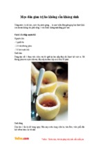
Three vaporizer positions, left-hand
configuration with arm display
mount.
Two vaporizer positions, left-hand
configuration with arm display
mount.
Three vaporizer positions, right-hand
configuration with arm display mount.
AA.96.102
AA.96.028
Two vaporizer positions, left-hand
configuration with basic display
mount.
AA.96.019
1-4
AA.96.016
AA.96.025
Aestiva
Pendant with arm display mount.
Figure 1-1 • Aestiva systems
1-4
1006-0938-000
1 Introduction
Symbols used in the manual or on the equipment
wWarnings and wCautions tell you about dangerous conditions that can
occur if you do not follow all instructions in this manual.
1-5
Warnings tell about a condition that can cause injury to the operator or the
patient.
Cautions tell about a condition that can cause damage to the equipment. Read
and follow all warnings and cautions.
Other symbols replace words on the equipment or in Datex-Ohmeda manuals.
No one device or manual uses all of the symbols. These symbols include:
On (power)
~
Alternating current
x
Protective earth ground
1006-0938-000
Off (power)
Standby
Standby or preparatory state for part of
the equipment
“ON” only for part of the equipment
“OFF” only for part of the equipment
Direct current
Í
m
µ
H
w
wW
N
N
l
O
o
q
p
œ
†
Not autoclavable
Type B equipment
Type BF equipment
Type CF equipment
Caution, ISO 7000-0434
Attention, refer to product
instructions, IEC 601-1
This way up
Dangerous Voltage
y
Earth ground
Electrical input
Electrical output
Pneumatic inlet
Pneumatic outlet
1-5
Aestiva
1-6
r
å
Y
Frame or chassis ground
REF
Stock Number
Alarm silence button
SN
Serial Number
Equipotential
Systems with this mark agree with
the European Council Directive
(93/42/EEC) for Medical Devices
when they are used as specified in
their Operation and Maintenance
Manuals. The xxxx is the
certification number of the
Notified Body used by DatexOhmeda’s Quality Systems.
t
Variability
Read top of float
T
Variability in steps
Vacuum inlet
+
Plus, positive polarity
Suction bottle outlet
P
Minus, negative polarity
Lamp, lighting, illumination
Cylinder
N
Movement in one direction
Isolation transformer
ˆ
Movement in two directions
Linkage system
z
Lock
Risk of Explosion
Z
Unlock
Low pressure leak test
1-6
O 2+
O2 Flush button
1006-0938-000
1 Introduction
134° C
R
u
q
t
Autoclavable
Bag position/ manual ventilation
Open drain (remove liquid)
Inspiratory flow
r
U
Q
1-7
Mechanical ventilation
Close drain
Expiratory flow
O2 sensor connection
End case
The primary regulator is set to pressure
less than 345 kPa.
The primary regulator is set to
pressure less than 414 kPa.
European Union Representative
1006-0938-000
1-7
Aestiva
1-8
1-8
1006-0938-000
2 System Controls
and Menus
2
In this section
Anesthesia system controls . . . . . . . . . . . . . . . . . . . . . . . . . . . . . . . . . . . . . . . . . . 2-2
Breathing system controls. . . . . . . . . . . . . . . . . . . . . . . . . . . . . . . . . . . . . . . . . . . . 2-5
Vaporizer controls . . . . . . . . . . . . . . . . . . . . . . . . . . . . . . . . . . . . . . . . . . . . . . . . . . 2-9
Ventilator controls . . . . . . . . . . . . . . . . . . . . . . . . . . . . . . . . . . . . . . . . . . . . . . . . .2-11
Optional flowmeter and suction regulators . . . . . . . . . . . . . . . . . . . . . . . . . . . . .2-19
Optional CO2 Bypass mode operation . . . . . . . . . . . . . . . . . . . . . . . . . . . . . . . . .2-21
1006-0938-000
2-1
Aestiva
Anesthesia system controls
w WARNING
Explosion Hazard. Do not use Aestiva systems with flammable
anesthetic agents.
w WARNING
Do not use antistatic breathing tubes or masks. They can cause
burns if you use them near high frequency surgical equipment.
AA.96.054
4
5
3
2
6
1
7
10
8
12
11
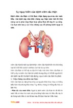
1.
2.
3.
4.
5.
6.
7.
8.
9.
10.
11.
12.
9
Breathing system (Figure 2-3)
Flow controls
Ventilator/monitoring display (Figure 2-5)
Light switch and Gooseneck lamp connector (some models)
Light (some models)
Dovetail rails
Vaporizers (Figure 2-4)
Gauge (cylinder pressure)
Gauge (pipeline pressure)
System switch
Flush button
Brake
Figure 2-1 • Aestiva (front view)
2-2
1006-0938-000
2 System Controls and Menus
Figure 2-1 shows these controls on the front of the Aestiva.
Description
System switch
Set the switch to on to permit gas flow and to turn on the
monitoring.
On
Flow controls
Standby
AA.96.103
Item
Turn the control counterclockwise to increase the flow and
clockwise to decrease. The system switch must be on.
Decrease
AA.96.105
Increase
Push O2 Flush to supply high flows of O2 to the breathing
system.
Light switch
Turns the light on and off.
AA.96.106
O2 flush
On
AA.96.107
Off
Push down to lock. Lift to release.
AA.96.100
Brake
1006-0938-000
2-3
2
Aestiva
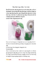
The circuit breakers are on the rear panel of the Aestiva.
Item
Description (Figure 2-2)
Circuit Breakers
System circuit breaker
AA.96.108
Open
(No Power)
Closed
(Power)
Open
(No Power)
AA.96.109
Outlet circuit breakers
Closed
(Power)
3
4
5
2
1
6
7
AA.96.053
8
1.
2.
3.
4.
5.
6.
7.
8.
Circuit Breaker for Electrical Outlet
Electrical Outlet
Circuit Breaker for Total Outlet Current
Circuit Breaker for Mains Inlet
Mains Inlet
Ventilator fuse
Pneumatic Outlet
Pipeline Connection
Figure 2-2 • Aestiva rear view
2-4
1006-0938-000
2 System Controls and Menus
Breathing system controls
9
8
10
2
7
11
6
5a
12
4
5b
3
2
AB.23.003
13
1
1.
2.
3.
4.
5.
Canister release
Auxiliary common gas outlet (optional)
Outlet switch (Auxiliary Common Gas Outlet)
Door
Flow sensor /patient connection (circuit connections)
a.Inspiratory (Circle circuit module) or to-fro connection (Mapleson/Bain circuit module)
b.Expiratory (Circle circuit module) or fresh gas connection (Mapleson/Bain circuit module)
6. Breathing circuit module (Circle)
7. Bag arm
8. Bag/Vent switch
9. APL valve
10.Bellows
11.Pressure gauge
12.Check valves
13. O2 sensor
Figure 2-3 • Breathing system parts
1006-0938-000
2-5
Aestiva
.
Item
Description
Bag/Vent switch
,
When you first turn on the system, mechanical
ventilation is always off. To start mechanical
ventilation, move the switch from Bag to Vent.
AB.23.059
Mechanical ventilation On (gas to bellows)
AB.23.060
Mechanical ventilation Off (gas to bag arm)
APL valve
Limits breathing system pressure during manual ventilation. The scale shows approximate
pressures. Above 30 cmH2O, you will feel clicks as the knob turns.
Increase
70
20
5
20
~0 cmH2O
~20 cmH2O
One arm is adjustable (push in and turn). The other is not.
Adjustable
AB.23.023
Not adjustable
2-6
AB.23.024
Bag arm
AB.23.064
30
5
30
70
1006-0938-000
- Xem thêm -