Accessed from 128.83.63.20 by nEwp0rt1 on Tue Jun 05 03:52:14 EDT 2012
Second Supplement to USP 35–NF 30
Physical Tests / 〈912〉 Rotational Rheometer Methods 5651
Calibration and Calculation of kinematic and Newtonian
viscosities of sample fluid: Proceed as directed in Method
I.■2S (USP35)
Add the following:
〈912〉 ROTATIONAL RHEOMETER
METHODS
.
■
The principle of the method is to measure the force (torque)
acting on a rotor when it rotates at a constant angular velocity (rotational speed) in a liquid. Rotational rheometers/viscometers are used for measuring the viscosity of Newtonian
fluids, i.e., a fluid having a viscosity that is independent of
the shearing stress or rate of shear, or the apparent viscosity
of non-Newtonian fluids, which may exhibit different rheological behavior, depending on shear rate, shear stress, and
temperature. The following procedures are used to determine
the viscosity of Newtonian fluids or the apparent viscosity of
non-Newtonian fluids. The calculated viscosity of Newtonian
fluids should be the same (within experimental error), regardless of the rate of shear (or rotational speed). Given the dependence of viscosity on temperature, the temperature of the
substance being measured should be controlled to within
±0.1°, unless otherwise specified in the individual monograph. Unless otherwise directed in the individual monograph, use Method I.
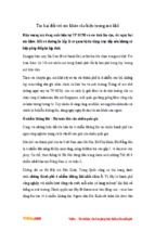
• METHOD I. SPINDLE RHEOMETERS (RELATIVE RHEOMETERS—SPINDLE VISCOMETERS)
Apparatus: In the spindle rheometer, the apparent viscosity
is determined by rotating a cylinder- or disc-shaped spindle,
as shown in Figures 1 and 2, respectively, immersed in a
large volume of liquid.
Figure 1. Cylinder-shaped spindles
Figure 2. Disc-shaped spindles
Procedure: Under these test conditions the shear rate varies
between the outer surface of the spindle and the inner surface of the beaker or cup containing the test substance. As a
result, the following additional information must be described along with the measured viscosity:
1. Size and geometry of spindle
2. Angular velocity of the spindle
3. Inner dimensions of the test substance container
4. Temperature of the test substance
5. Use of instrument accessories, such as a spindle guard
The preparation of the test specimen, including its temperature equilibration, is specified in each individual monograph. Follow the instrument manufacturer’s recommendations regarding sample loading, spindle selection, and
rheometer operation.
Calibration: Select at least two calibration standards whose
viscosities differ by an appropriate value within the viscosity
range of the test substance under measurement for a particular rheometer configuration. Measure the apparent viscosities of each standard, as described above, at multiple rotational speeds.
A rheometer is deemed to be calibrated if the measured
apparent viscosities are within ±5% of the stated values.
Generally, calibration, operation, and cleaning of rheometers
should be performed according to the recommendations of
the instrument manufacturer.
• METHOD II. CONCENTRIC CYLINDER RHEOMETERS
Apparatus: In the concentric cylinder rheometer, the apparent viscosity is determined by placing the liquid in the gap
between the inner cylinder and the outer cylinder. Both controlled-stress and controlled-rate rotational rheometers are
available commercially in configurations with absolute geometries (e.g., very small annular gaps between concentric
cylinders) that can provide consistent meaningful rheological
data for non-Newtonian fluids. Controlled-stress rheometers
provide controlled-stress input and measurement of the resulting shear rate. Controlled-rate rheometers provide controlled-shear rate input and determination of the resultant
shear stress, measured as torque, on the rotor axis. Concen-
Official from December 1, 2012
Copyright (c) 2012 The United States Pharmacopeial Convention. All rights reserved.
Accessed from 128.83.63.20 by nEwp0rt1 on Tue Jun 05 03:52:14 EDT 2012
5652 〈912〉 Rotational Rheometer Methods / Physical Tests
Second Supplement to USP 35–NF 30
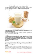
tric cylinder rotational rheometers are sometimes referred to
as cup-and-bob rheometers. These rheometers involve an
additional design consideration depending on whether the
outer cylinder (the cup) or the inner cylinder (the bob) rotates. Rotating-cup rheometers are called Couette systems,
while rotating-bob rheometers are called Searle systems, as
shown in Figures 3 and 4, respectively.
Figure 4. Searle concentric cylinder system for rotational
rheometry
Figure 3. Couette concentric cylinder system for rotational
rheometry
Procedure: Place a sufficient quantity of a test solution or
fluid in the rheometer, and allow the sample to reach thermal equilibrium, as indicated in the individual monograph.
Operate the rheometer following the procedure recommended by the instrument manufacturer. For nonNewtonian systems, the monograph indicates the type of
rheometer that should be used and the shear rate(s) at
Official from December 1, 2012
Copyright (c) 2012 The United States Pharmacopeial Convention. All rights reserved.
Accessed from 128.83.63.20 by nEwp0rt1 on Tue Jun 05 03:52:14 EDT 2012
Second Supplement to USP 35–NF 30
Physical Tests / 〈912〉 Rotational Rheometer Methods 5653
which the measurements should be made. [NOTE—If there is
evidence of time-dependent (e.g., thixotropic or rheopectic)
rheological behavior, this should be noted as well.] As noted
above, apparent viscosity should be determined preferably
over a range of shear rates appropriate to the material under
test. The procedure employed to measure the apparent viscosity of the liquid is repeated, using a series of different
rotational speeds or torques. From a series of such viscosity
measurements, the relationship between the shear rate and
the shear stress of a non-Newtonian liquid—that is, the flow
characteristics of the non-Newtonian liquid—can be
obtained.
Calculation of shear rate, shear stress, and viscosity: For
non-Newtonian liquids, it is essential to specify the shear
stress, σ, or the shear rate , at which the viscosity is measured. Under narrow gap conditions (conditions satisfied in
absolute rheometers), the shear rate
in s−1, and the shear
stress σ, in Pa (N · m−2 or kg · m−1 · s−2), are calculated using
Equations (1) and (2) below:
RO
RI
ω
M
h
Calibration: Rotational rheometers require calibration with
rheological standards appropriate for the shear rate or shear
stress ranges and the nature of the fluid or material under
evaluation. To determine or confirm the apparatus constant,
perform the necessary tests beforehand, using fluids of
known viscosities of appropriate viscosity standards at the
required temperature.
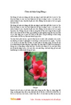
• METHOD III. CONE-AND-PLATE RHEOMETERS
Apparatus: In the cone-and-plate rheometer, the liquid is
introduced into the gap between a flat disc or plate and a
cone forming a defined angle. Viscosity measurement can
be performed by rotating the cone or the plate, as shown in
Figures 5 and 6, respectively. [NOTE—Because the volume of
sample is small, even a small absolute loss of solvents can
cause a large percentage change in viscosity. Such a loss is
particularly relevant for volatile solvents but could be
significant even for nonvolatile solvents such as water.]
=
=
=
=
=
radius of the outer cylinder (m)
radius of the inner cylinder (m)
angular velocity (radians/s)
torque acting on the cylinder surface (N · m)
height of immersion of the inner cylinder in the
liquid medium (m)
Generally, the angular velocity can be calculated using
Equation (3):
n
= rotational speed, in revolutions/min (rpm)
For laminar flow, the viscosity η (or apparent viscosity ηApp),
in Pa · s , is given by the following equation:
[NOTE—1 Pa · s = 1000 mPa · s.]
k
= the constant of the apparatus (radians/m3)
Figure 5. Cone-and-plate rotational rheometer with rotating
cone
Official from December 1, 2012
Copyright (c) 2012 The United States Pharmacopeial Convention. All rights reserved.
Accessed from 128.83.63.20 by nEwp0rt1 on Tue Jun 05 03:52:14 EDT 2012
5654 〈912〉 Rotational Rheometer Methods / Physical Tests
Second Supplement to USP 35–NF 30
α
Figure 6. Cone-and-plate rotational rheometer with rotating
plate
Procedure: Proceed as directed for Method II. Concentric
Cylinder Rheometers.
Calculation of shear rate, shear stress, and viscosity: The
shear rate
in s−1, and the shear stress σ, in Pa, are
calculated by Equations (5) and (6).
= angle between the flat plate and the cone
(radians)
R
= radius of the cone (m)
ω
= angular velocity (radians/s)
M
= torque acting on the flat plate or cone surface
(N · m)
For laminar flow, the viscosity η (or apparent viscosity ηApp),
in Pa · s, is given by the following equation:
k
= constant of the apparatus (radians/m3)
Calibration: Proceed as directed for Calibration in Method II.
Concentric Cylinder Rheometers.■2S (USP35)
Official from December 1, 2012
Copyright (c) 2012 The United States Pharmacopeial Convention. All rights reserved.
Accessed from 128.83.63.20 by nEwp0rt1 on Tue Jun 05 03:52:14 EDT 2012
Second Supplement to USP 35–NF 30
Add the following:
〈913〉 ROLLING BALL
VISCOMETER METHOD
■
The following procedure is used to determine the viscosity
of a Newtonian fluid, i.e., a fluid having a viscosity that is
independent of the shearing stress or rate of shear.
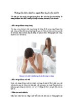
Apparatus: See Figure 1.
The basic design of a rolling ball viscometer consists of a
tube (or capillary) that contains the sample liquid under test
and a ball chosen so that it will require a minimum rolling
time of 20 s at the measuring angle in the sample liquid.
Physical Tests / 〈913〉 Rolling Ball Viscometer Method 5655
each single measured rolling time, the resulting viscosity can
be expressed as dynamic viscosity (mPa · s) as well as kinematic viscosity (mm2/s) for a sample of known density.
Procedure: Select a measuring system [tube (or capillary)
and ball combination] within the anticipated range of viscosity of the sample liquid. As necessary, heat the clean and
dry tube and ball of the viscometer to the temperature
specified in the individual monograph, and control the temperature to ±0.1°, unless otherwise specified in the individual monograph. Select a measuring angle to obtain a minimum rolling time of 20 s. Fill the tube with the sample
liquid, being careful to avoid bubble formation. Close the
tube, and insert it in the instrument. Allow to equilibrate at
the specified temperature for NLT 15 min for a rolling ball
viscometer with a tube of large diameter. For a micro rolling
ball viscometer, follow the instrument manufacturer’s instructions regarding temperature equilibration. Release the
ball, and record the time required for the ball to roll from
the upper to the lower ring mark (or measuring sensor).
Repeat the test run at least four times.
The rolling time in the fluid under examination is the
mean of NLT four consecutive determinations. The result is
valid if the percent relative standard deviation (%RSD) for
the four readings is NMT 2.0%.
Calculation and Calibration: Calculate the Newtonian viscosity, η, in mPa · s, using the formula:
η = k × (ρ1 − ρ2) × t
Figure 1. Basic design for rolling ball viscometer.
Measuring Principle: The rolling ball measurement is
based on Stokes’s Law, as influenced by the angle of inclination of the tube (or capillary). The Newtonian viscosity, η, in
mPa · s, is calculated using the following equation:
η = [(ρ1 − ρ2) × g × r2 × sinθ] / v∞
ρ1 = density of the ball used (g/mL)
ρ2 = density of the sample liquid (g/mL)
g = gravitational constant (mm/s2)
r = radius of the ball (mm)
θ = angle of inclination of the tube (or capillary)
v∞ = terminal velocity of the ball (mm/s)
Determine the viscosity of a liquid by observing the rolling time of a solid sphere (ball) under the influence of gravity in an inclined cylindrical tube filled with the sample liquid. Measure the time taken by the ball to travel the fixed
distance between two ring marks or measuring sensors. For
k = calibration constant of the instrument (mm2/s2) at a
specified measuring angle and temperature
ρ1 = density of the ball used (g/mL)
ρ2 = density of the sample liquid (g/mL)
t = rolling time of the ball (s).
Calibrate each tube (or capillary) and ball combination at
the test temperature and test angle using fluids of known
viscosities and densities (viscosity standards) to determine
the measuring system constant, k. [NOTE—Some automated
viscometers use a polynomial function to determine the calibration for different angles and temperatures.] The viscosity
values of the calibration standards should bracket the expected viscosity value of the sample liquid.
Calibrations are specific to the ball radius, ball density,
temperature, and test angle. Recalibration is necessary when
any of these parameters is changed.
Where no reference values at the required test temperature are available, follow the manufacturer’s instructions for
mathematical corrections to the calibration function. When
the materials of the ball and tube are dissimilar, apply corrections calculated using the linear thermal expansion coefficients of the materials.■2S (USP35)
Official from December 1, 2012
Copyright (c) 2012 The United States Pharmacopeial Convention. All rights reserved.
- Xem thêm -