Accessed from 128.83.63.20 by nEwp0rt1 on Tue Jun 05 05:18:06 EDT 2012
Physical Tests / 〈911〉 Viscosity 5649
Second Supplement to USP 35–NF 30
Change to read:
〈911〉 VISCOSITY■—CAPILLARY
VISCOMETER METHODS
.
The following procedures are used to determine the viscosity of
a Newtonian fluid, i.e. a fluid having a viscosity that is inde-
pendent of the shearing stress rate or rate of shear. Unless
otherwise directed in the individual monograph, use Method
I.
• METHOD I. UBBELOHDE-TYPE CAPILLARY VISCOMETER
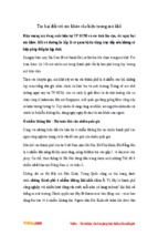
Apparatus: The determination may be carried out with an
Ubbelohde-type capillary viscometer (Figure 1) that has the
specifications described in Table 1 or Table 2.
Table 1
Size
Number
1
1A
2
2A
3
3A
4
4A
5
Nominal
Constant
of Viscometer
(mm2/s2)
0.01
0.03
0.1
0.3
1.0
3.0
10
30
100
Measurable
Kinematic
Viscosity Range
(mm2/s)
3.5–10
6–30
20–100
60–300
200–1,000
600–3,000
2,000–10,000
6,000–30,000
20,000–100,000
Internal
Diameter
of Tube,
R (mm) (±2%)
0.64
0.84
1.15
1.51
2.06
2.74
3.70
4.07
6.76
Volume
of Bulb,
C (mL) (±5%)
5.6
5.6
5.6
5.6
5.6
5.6
5.6
5.6
5.6
Internal
Diameter
of Tube,
N (mm)
2.8–3.2
2.8–3.2
2.8–3.2
2.8–3.2
3.7–4.3
4.6–5.4
4.6–5.4
5.6–6.4
6.8–7.5
Volume
of Bulb,
C (mL) (±5%)
1.0
2.0
3.0
4.0
4.0
4.0
4.0
4.0
4.0
4.0
4.0
4.0
4.0
4.0
5.0
5.0
Internal
Diameter
of Tube,
N (mm)
6.0
6.0
6.0
6.0
6.0
6.0
6.0
6.0
6.0
6.0
6.0
6.5
7.0
8.0
8.5
10.0
Table 2
Size
Number
0
0C
0B
1
1C
1B
2
2C
2B
3
3C
3B
4
4C
4B
5
Nominal
Constant
of Viscometer
(mm2/s2)
0.001
0.003
0.005
0.01
0.03
0.05
0.1
0.3
0.5
1.0
3.0
5.0
10
30
50
100
Measurable
Kinematic
Viscosity Range
(mm2/s)
0.3–1
0.6–3
1–5
2–10
6–30
10–50
20–100
60–300
100–500
200–1,000
600–3,000
1,000–5,000
2,000–10,000
6,000–30,000
10,000–50,000
20,000–100,000
Internal
Diameter
of Tube,
R (mm) (±2%)
0.24
0.36
0.46
0.58
0.78
0.88
1.03
1.36
1.55
1.83
2.43
2.75
3.27
4.32
5.20
6.25
Official from December 1, 2012
Copyright (c) 2012 The United States Pharmacopeial Convention. All rights reserved.
Accessed from 128.83.63.20 by nEwp0rt1 on Tue Jun 05 05:18:06 EDT 2012
5650 〈911〉 Viscosity / Physical Tests
Second Supplement to USP 35–NF 30
flow time, t, ranges between 200 and 1000 s, and the
kinematic energy correction is typically less than 1%. If the
viscosity constant, k, is known, use the following equation to
calculate the kinematic viscosity, v, in mm2/s, from the flow
time, t, in s.
v=k×t
If the density of the fluid is known at the temperature of the
viscosity measurement, then the Newtonian viscosity, η, in
mPa · s, is calculated by the following equation:
η=v×ρ
ρ
= density of the fluid (g/mL)
The flow time of the fluid under examination is the mean of
NLT three consecutive determinations. The result is valid if
the percentage of the relative standard deviation (%RSD)
for the three readings is NMT 2.0%.
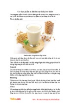
• METHOD II. OSTWALD-TYPE CAPILLARY VISCOMETER
Apparatus: The determination may be carried out with an
Ostwald-type capillary viscometer (Figure 2).
Figure 1. Ubbelohde-Type Capillary Viscometer
Procedure: Fill the viscometer through tube (L) with a sufficient quantity of the sample liquid that is appropriate for
the viscometer being used or by following the manufacturer’s instructions. Carry out the experiment with the tube in
a vertical position. Fill bulb (A) with the liquid, and also
ensure that the level of liquid in bulb (B) is below the exit to
the ventilation tube (M). Immerse the viscometer in a water
or oil bath stabilized at the temperature specified in the individual monograph, and control the temperature to ±0.1°,
unless otherwise specified in the individual monograph.
Maintain the viscometer in a vertical position for a time period of NLT 30 min to allow the sample temperature to
reach equilibrium. Close tube (M), and raise the level of the
liquid in tube (N) to a level about 8 mm above mark (E ≡
h1). Keep the liquid at this level by closing tube (N) and
opening tube (M). Open tube (N), and measure the time
required for the level of the liquid to drop from mark (E ≡
h1) to (F ≡ h2), using an appropriate accurate timing device.
[NOTE—In Table 1, the minimum flow time should be 350 s
for size no. 1, and 200 s for all other sizes. In Table 2, the
minimum flow time should be 300 s for size no. 0, and 200
s for all other sizes.]
Calibration: Calibrate each viscometer at the test temperature by using fluids of known viscosities of appropriate viscosity standards to determine the viscometer constant, k.
The viscosity values of the calibration standards should
bracket the expected viscosity value of the sample liquid.
Determine the viscometer constant at the same temperature
as the sample liquid under test.
Calculate the viscometer constant, k, in mm2/s2, from the
equation:
k = η/(ρ × t)
η
ρ
t
= known viscosity of the liquid (mPa · s)
= density of the liquid (g/mL)
= flow time for the liquid to pass from the upper
mark to the lower mark (s)
Calculation of kinematic and Newtonian viscosities of
sample fluid: A capillary viscometer is chosen so that the
Figure 2. Ostwald-Type Capillary Viscometer
Procedure: Fill the tube with an amount of the sample that
is appropriate for the viscometer being used or by following
the manufacturer’s instructions. The volume of fluid used
should be such that the lower bulb is not entirely emptied
when the fluid is drawn up through the capillary tube to the
uppermost graduation mark. Carry out the experiment with
the tube in a vertical position. Immerse the viscometer in a
water or oil bath stabilized at the temperature specified in
the individual monograph, and control the temperature to
±0.1°, unless otherwise specified in the individual
monograph. Maintain the viscometer in a vertical position
for a time period of NLT 30 min to allow the sample
temperature to reach equilibrium. Using suction, draw the
fluid up through the capillary tube until the meniscus is at
the level of the uppermost graduation. With both the filling
and capillary tubes open to atmospheric pressure, record the
time, in s, required for the liquid to flow from the upper
mark to the lower mark in the capillary tube. [NOTE—The
minimum flow time should be 200 s.]
Official from December 1, 2012
Copyright (c) 2012 The United States Pharmacopeial Convention. All rights reserved.
Accessed from 128.83.63.20 by nEwp0rt1 on Tue Jun 05 05:18:06 EDT 2012
Second Supplement to USP 35–NF 30
Physical Tests / 〈912〉 Rotational Rheometer Methods 5651
Calibration and Calculation of kinematic and Newtonian
viscosities of sample fluid: Proceed as directed in Method
I.■2S (USP35)
Add the following:
〈912〉 ROTATIONAL RHEOMETER
METHODS
.
■
The principle of the method is to measure the force (torque)
acting on a rotor when it rotates at a constant angular velocity (rotational speed) in a liquid. Rotational rheometers/viscometers are used for measuring the viscosity of Newtonian
fluids, i.e., a fluid having a viscosity that is independent of
the shearing stress or rate of shear, or the apparent viscosity
of non-Newtonian fluids, which may exhibit different rheological behavior, depending on shear rate, shear stress, and
temperature. The following procedures are used to determine
the viscosity of Newtonian fluids or the apparent viscosity of
non-Newtonian fluids. The calculated viscosity of Newtonian
fluids should be the same (within experimental error), regardless of the rate of shear (or rotational speed). Given the dependence of viscosity on temperature, the temperature of the
substance being measured should be controlled to within
±0.1°, unless otherwise specified in the individual monograph. Unless otherwise directed in the individual monograph, use Method I.
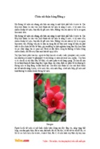
• METHOD I. SPINDLE RHEOMETERS (RELATIVE RHEOMETERS—SPINDLE VISCOMETERS)
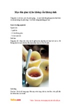
Apparatus: In the spindle rheometer, the apparent viscosity
is determined by rotating a cylinder- or disc-shaped spindle,
as shown in Figures 1 and 2, respectively, immersed in a
large volume of liquid.
Figure 1. Cylinder-shaped spindles
Figure 2. Disc-shaped spindles
Procedure: Under these test conditions the shear rate varies
between the outer surface of the spindle and the inner surface of the beaker or cup containing the test substance. As a
result, the following additional information must be described along with the measured viscosity:
1. Size and geometry of spindle
2. Angular velocity of the spindle
3. Inner dimensions of the test substance container
4. Temperature of the test substance
5. Use of instrument accessories, such as a spindle guard
The preparation of the test specimen, including its temperature equilibration, is specified in each individual monograph. Follow the instrument manufacturer’s recommendations regarding sample loading, spindle selection, and
rheometer operation.
Calibration: Select at least two calibration standards whose
viscosities differ by an appropriate value within the viscosity
range of the test substance under measurement for a particular rheometer configuration. Measure the apparent viscosities of each standard, as described above, at multiple rotational speeds.
A rheometer is deemed to be calibrated if the measured
apparent viscosities are within ±5% of the stated values.
Generally, calibration, operation, and cleaning of rheometers
should be performed according to the recommendations of
the instrument manufacturer.
• METHOD II. CONCENTRIC CYLINDER RHEOMETERS
Apparatus: In the concentric cylinder rheometer, the apparent viscosity is determined by placing the liquid in the gap
between the inner cylinder and the outer cylinder. Both controlled-stress and controlled-rate rotational rheometers are
available commercially in configurations with absolute geometries (e.g., very small annular gaps between concentric
cylinders) that can provide consistent meaningful rheological
data for non-Newtonian fluids. Controlled-stress rheometers
provide controlled-stress input and measurement of the resulting shear rate. Controlled-rate rheometers provide controlled-shear rate input and determination of the resultant
shear stress, measured as torque, on the rotor axis. Concen-
Official from December 1, 2012
Copyright (c) 2012 The United States Pharmacopeial Convention. All rights reserved.
- Xem thêm -