Accessed from 128.83.63.20 by nEwp0rt1 on Tue Jun 05 03:46:33 EDT 2012
5642 〈696〉 Crystalline Solids / Physical Tests
each sample. The mean of these values is then calculated.
The exact requirements will depend on the equipment capability and degree of accuracy needed.
Isoperibol Solution Calorimetry
In the isoperibol solution calorimeter, the heat change
during the solution process causes a corresponding change
in temperature of the solvent–solute system (i.e., solution).
This temperature change is measured by a temperature sensor, which is wired to an electrical circuit that records an
electrical signal corresponding to the temperature change.
Typically, this temperature change in an electronic form is
measured at precisely defined time intervals to produce
temperature–time data that are collected, analyzed by a
computer, and then plotted. A blank run without addition
of the solid solute to the solvent normally shows no discernible change in the slope of the temperature–time plot.
For isoperibol solution calorimeters, response is fairly
rapid, but corrections must be made for any heat losses to
or heat gains from the bath. Therefore, isoperibol solution
calorimeters are more advantageous than isothermal solution calorimeters when the solution process is relatively fast.
For all measurements of enthalpy of solution using isoperibol solution calorimeters, the choice of solvent is critical.
The nature and mass of the solvent and the mass of sample
allow the total heat change, corresponding to total dissolution of the solid, to proceed to completion within five min
under vigorous stirring at a constant rotational speed within
the range of 400–600 revolutions/min.
The effective heat capacity of the calorimeter cell and its
contents is determined for every calorimeter run. This determination is accomplished by electrical heating of the contents of the calorimeter cell. The effective heat capacity is
determined according to one of two protocols—either by
making one determination after ampul breakage or by making one determination before and a second determination
after ampul breakage, and then averaging the two results.
The accuracy and reliability of the electrical heating are established by the accuracy and reliability of the aforementioned chemical calibrations.
Isothermal Solution Calorimetry
In the isothermal (constant temperature) solution calorimeter, the heat change during the solution process is compensated for by an equal but opposite energy change, such
that the temperature of the solvent–solute system (i.e., solution) remains essentially constant. This equal but opposite
energy change is measured and, when its sign is reversed,
provides the enthalpy of solution. For isothermal calorimeters, response is relatively slow, but the compensation process eliminates the effects of heat losses to or heat gains
from the bath. Therefore, isothermal calorimeters are more
advantageous than isoperibol calorimetry when the solution
process is relatively slow.
Second Supplement to USP 35–NF 30
Sample Handling
The chemical and physical stability of solids may decrease
with decreasing crystallinity. In particular, solids of low crystallinity, especially amorphous solids, tend to sorb water vapor from the atmosphere, leading to crystallization and a
corresponding gain in crystallinity. For these reasons, anhydrous samples whose crystallinity is to be determined must
be stored at zero humidity or below critical humidity levels
in sealed chambers containing a desiccant, preferably containing an indicator of effectiveness. If crystallinity–humidity
studies are to be carried out, the sample is stored in a
sealed chamber containing a saturated salt solution to provide a defined relative humidity.■2S (USP35)
〈711〉 DISSOLUTION
This general chapter is harmonized with the corresponding texts of the European Pharmacopoeia and/or the Japanese
Pharmacopoeia. These pharmacopeias have undertaken not
to make any unilateral change to this harmonized chapter.
Portions of the present general chapter text that are national USP text, and therefore not part of the harmonized
text, are marked with symbols (✦✦) to specify this fact.
This test is provided to determine compliance with the
dissolution requirements ✦where stated in the individual
monograph✦ for dosage forms administered orally. In this
general chapter, a dosage unit is defined as 1 tablet or 1
capsule or the amount specified. ✦Of the types of apparatus
described herein, use the one specified in the individual
monograph. Where the label states that an article is entericcoated, and where a dissolution or disintegration test that
does not specifically state that it is to be applied to delayedrelease articles is included in the individual monograph, the
procedure and interpretation given for Delayed-Release Dosage Forms is applied unless otherwise specified in the individual monograph. For hard or soft gelatin capsules and gelatin-coated tablets that do not conform to the Dissolution
specification, repeat the test as follows. Where water or a
medium with a pH of less than 6.8 is specified as the Medium in the individual monograph, the same Medium specified may be used with the addition of purified pepsin that
results in an activity of 750,000 Units or less per 1000 mL.
For media with a pH of 6.8 or greater, pancreatin can be
added to produce not more than 1750 USP Units of protease activity per 1000 mL.
Change to read:
USP Reference Standards 〈11〉—•• (RB 1-Feb-2012) USP Prednisone Tablets RS.✦
Solution Calorimeter Calibration
To ensure the accuracy of the calorimeter, chemical calibrations must be performed on a regular basis. For an endothermic solution process, the calibration of the calorimeter is
checked by measuring the heat absorbed during the dissolution of potassium chloride in distilled water at 298.15 K
(25.0°). The established enthalpy change in this endothermic process is 235.5 J/g (17.56 kJ/mol). For an exothermic
solution process, the calorimeter is checked by measuring
the heat evolved during the dissolution of 5 g/L of
tromethamine [tris(hydroxymethyl)aminomethane, THAM]
in a 0.1 mol/L aqueous hydrochloric acid solution at 298.15
K (25.0°). The established heat for the aforementioned process is −246.0 J/g (−29.80 kJ/mol).
Change to read:
APPARATUS
Apparatus 1 (Basket Apparatus)
The assembly consists of the following: a vessel, which
may be covered, made of glass or other inert, transparent
Official from December 1, 2012
Copyright (c) 2012 The United States Pharmacopeial Convention. All rights reserved.
Accessed from 128.83.63.20 by nEwp0rt1 on Tue Jun 05 03:46:33 EDT 2012
Physical Tests / 〈711〉 Dissolution 5643
Second Supplement to USP 35–NF 30
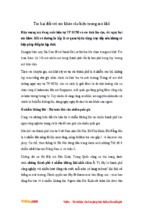
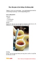
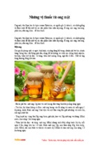
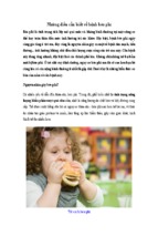
Figure 1. Basket stirring element.
material1; a motor; a metallic drive shaft; and a cylindrical
basket. The vessel is partially immersed in a suitable water
bath of any convenient size or heated by a suitable device
such as a heating jacket. The water bath or heating device
permits holding the temperature inside the vessel at
37 ± 0.5° during the test and keeping the bath fluid in constant, smooth motion. No part of the assembly, including
the environment in which the assembly is placed, contributes significant motion, agitation, or vibration beyond that
due to the smoothly rotating stirring element. An apparatus
that permits observation of the specimen and stirring element during the test is preferable. The vessel is cylindrical,
with a hemispherical bottom and ✦with one of the following
dimensions and capacities: for a nominal✦ capacity of 1 L,
the height is 160 to 210 mm and its inside diameter is 98
to 106 mm; ✦for a nominal capacity of 2 L, the height is
280 to 300 mm and its inside diameter is 98 to 106 mm;
and for a nominal capacity of 4 L, the height is 280 to 300
mm and its inside diameter is 145 to 155 mm✦. Its sides are
flanged at the top. A fitted cover may be used to retard
evaporation.2 The shaft is positioned so that its axis is not
more than 2 mm at any point from the vertical axis of the
vessel and rotates smoothly and without significant wobble
The materials should not sorb, react, or interfere with the specimen being
tested.
2 If a cover is used, it provides sufficient openings to allow ready insertion of
the thermometer and withdrawal of specimens.
1
that could affect the results. A speed-regulating device is
used that allows the shaft rotation speed to be selected and
maintained at the specified rate ✦given in the individual
monograph✦ within ±4%.
Shaft and basket components of the stirring element are
fabricated of stainless steel, type 316, or other inert material, to the specifications shown in Figure 1. A basket having
a gold coating of about 0.0001 inch (2.5 µm) thick may be
used. A dosage unit is placed in a dry basket at the beginning of each test. The distance between the inside bottom
of the vessel and the bottom of the basket is maintained at
25 ± 2 mm during the test.
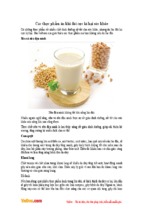
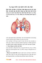
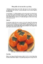
Apparatus 2 (Paddle Apparatus)
Use the assembly from Apparatus 1, except that a paddle
formed from a blade and a shaft is used as the stirring element. The shaft is positioned so that its axis is not more
than 2 mm from the vertical axis of the vessel at any point
and rotates smoothly without significant wobble that could
affect the results. The vertical center line of the blade passes
through the axis of the shaft so that the bottom of the
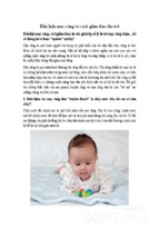
blade is flush with the bottom of the shaft. The paddle conforms to the specifications shown in Figure 2. The distance
of 25 ± 2 mm between the bottom of the blade and the
inside bottom of the vessel is maintained during the test.
Official from December 1, 2012
Copyright (c) 2012 The United States Pharmacopeial Convention. All rights reserved.
Accessed from 128.83.63.20 by nEwp0rt1 on Tue Jun 05 03:46:33 EDT 2012
5644 〈711〉 Dissolution / Physical Tests
The metallic or suitably inert, rigid blade and shaft comprise
a single entity. A suitable two-part detachable design may
be used provided the assembly remains firmly engaged during the test. The paddle blade and shaft may be coated
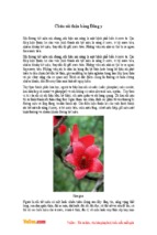
with a suitable coating so as to make them inert. The dosage unit is allowed to sink to the bottom of the vessel
before rotation of the blade is started. A small, loose piece
of nonreactive material, such as not more than a few turns
of wire helix, may be attached to dosage units that would
otherwise float. An alternative sinker device is shown in Figure 2a. Other validated sinker devices may be used.
Second Supplement to USP 35–NF 30
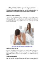
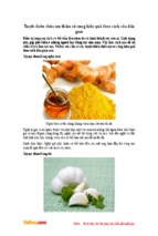
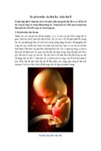
and screens that are made of suitable nonsorbing and
nonreactive material and that are designed to fit the tops
and bottoms of the reciprocating cylinders; and a motor
and drive assembly to reciprocate the cylinders vertically inside the vessels and, if desired, index the reciprocating cylinders horizontally to a different row of vessels. The vessels are
partially immersed in a suitable water bath of any convenient size that permits holding the temperature at 37 ± 0.5°
during the test. No part of the assembly, including the environment in which the assembly is placed, contributes significant motion, agitation, or vibration beyond that due to the
smooth, vertically reciprocating cylinder. A device is used
that allows the reciprocation rate to be selected and maintained at the specified dip rate ✦given in the individual
monograph✦ within ±5%. An apparatus that permits observation of the specimens and reciprocating cylinders is preferable. The vessels are provided with an evaporation cap
that remains in place for the duration of the test. The components conform to the dimensions shown in Figure 3 unless otherwise specified ✦in the individual monograph✦.
Figure 2. Paddle stirring element.
Figure 2a. Alternative sinker. All dimensions are expressed in
mm.
Apparatus 3 (Reciprocating Cylinder)
NOT ACCEPTED BY THE JAPANESE PHARMACOPOEIA
The assembly consists of a set of cylindrical, flat-bottomed
glass vessels; a set of glass reciprocating cylinders; inert fittings (stainless steel type 316 or other suitable material),
Figure 3. Apparatus 3 (reciprocating cylinder).
Apparatus 4 (Flow-Through Cell)
The assembly consists of a reservoir and a pump for the
Dissolution Medium; a flow-through cell; and a water bath
Official from December 1, 2012
Copyright (c) 2012 The United States Pharmacopeial Convention. All rights reserved.
Accessed from 128.83.63.20 by nEwp0rt1 on Tue Jun 05 03:46:33 EDT 2012
Second Supplement to USP 35–NF 30
Physical Tests / 〈711〉 Dissolution 5645
that maintains the Dissolution Medium at 37 ± 0.5°. Use the
specified cell size ✦as given in the individual monograph✦.
The pump forces the Dissolution Medium upwards through
the flow-through cell. The pump has a delivery range between 240 and 960 mL per hour, with standard flow rates
of 4, 8, and 16 mL per minute. It must deliver a constant
flow (±5% of the nominal flow rate); the flow profile is sinusoidal with a pulsation of 120 ± 10 pulses per minute. A
pump without pulsation may also be used. Dissolution test
procedures using a flow-through cell must be characterized
with respect to rate and any pulsation.
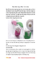
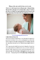
The flow-through cell (see Figures 4 and 5), of transparent
and inert material, is mounted vertically with a filter system
(specified in the individual monograph) that prevents escape
of undissolved particles from the top of the cell; standard
cell diameters are 12 and 22.6 mm; the bottom cone is
usually filled with small glass beads of about 1-mm diameter
with one bead of about 5 mm positioned at the apex to
protect the fluid entry tube; and a tablet holder (see Figures
4 and 5) is available for positioning of special dosage forms,
for example, inlay tablets. The cell is immersed in a water
bath, and the temperature is maintained at 37 ± 0.5°.
Figure 5. Apparatus 4, small cell for tablets and capsules
(top), tablet holder for the small cell (bottom). (All measurements are expressed in mm unless noted otherwise.)
The apparatus uses a clamp mechanism and two O-rings
to assemble the cell. The pump is separated from the dissolution unit in order to shield the latter against any vibrations
originating from the pump. The position of the pump
should not be on a level higher than the reservoir flasks.
Tube connections are as short as possible. Use suitably inert
tubing, such as polytef, with about 1.6-mm inner diameter
and chemically inert flanged-end connections.
APPARATUS SUITABILITY
Figure 4. Apparatus 4, large cell for tablets and capsules
(top), tablet holder for the large cell (bottom). (All measurements are expressed in mm unless noted otherwise.)
The determination of suitability of a test assembly to perform dissolution testing must include conformance to the
dimensions and tolerances of the apparatus as given above.
In addition, critical test parameters that have to be monitored periodically during use include volume and temperature of the Dissolution Medium, rotation speed (Apparatus 1
and Apparatus 2), dip rate (Apparatus 3), and flow rate of
medium (Apparatus 4).
Determine the acceptable performance of the dissolution
test assembly periodically. ✦The suitability for the individual
apparatus is demonstrated by the Performance Verification
Test.
Performance Verification Test, Apparatus 1 and 2—
Test USP Prednisone Tablets RS according to the operating
Official from December 1, 2012
Copyright (c) 2012 The United States Pharmacopeial Convention. All rights reserved.
Accessed from 128.83.63.20 by nEwp0rt1 on Tue Jun 05 03:46:33 EDT 2012
5646 〈711〉 Dissolution / Physical Tests
conditions specified. The apparatus is suitable if the results
obtained are within the acceptable range stated in the technical data sheet specific to the lot used and the apparatus
tested.
Performance Verification Test, Apparatus 3—•[To
come.]• (RB 1-Feb-2012)
Performance Verification Test, Apparatus 4—[To
come.]✦
PROCEDURE
Apparatus 1 and Apparatus 2
IMMEDIATE-RELEASE DOSAGE FORMS
Place the stated volume of the Dissolution Medium (±1%)
in the vessel of the specified apparatus ✦given in the individual monograph✦, assemble the apparatus, equilibrate the
Dissolution Medium to 37 ± 0.5°, and remove the thermometer. Place 1 dosage unit in the apparatus, taking care to
exclude air bubbles from the surface of the dosage unit, and
immediately operate the apparatus at the specified rate
✦given in the individual monograph . Within the time inter✦
val specified, or at each of the times stated, withdraw a
specimen from a zone midway between the surface of the
Dissolution Medium and the top of the rotating basket or
blade, not less than 1 cm from the vessel wall. [NOTE—
Where multiple sampling times are specified, replace the aliquots withdrawn for analysis with equal volumes of fresh
Dissolution Medium at 37° or, where it can be shown that
replacement of the medium is not necessary, correct for the
volume change in the calculation. Keep the vessel covered
for the duration of the test, and verify the temperature of
the mixture under test at suitable times.] Perform the analysis ✦as directed in the individual monograph✦ using a suitable assay method.3 Repeat the test with additional dosage
form units.
If automated equipment is used for sampling or the apparatus is otherwise modified, verification that the modified
apparatus will produce results equivalent to those obtained
with the standard apparatus described in this general chapter is necessary.
Dissolution Medium—A suitable dissolution medium is
used. Use the solvent specified ✦in the individual
monograph✦. The volume specified refers to measurements
made between 20° and 25°. If the Dissolution Medium is a
buffered solution, adjust the solution so that its pH is within
0.05 unit of the specified pH ✦given in the individual
monograph✦. [NOTE—Dissolved gases can cause bubbles to
form, which may change the results of the test. If dissolved
gases influence the dissolution results, dissolved gases
should be removed prior to testing.4]
Time—Where a single time specification is given, the test
may be concluded in a shorter period if the requirement for
minimum amount dissolved is met. Specimens are to be
withdrawn only at the stated times within a tolerance of
±2%.
✦Procedure for a Pooled Sample for ImmediateRelease Dosage Forms—Use this procedure where Procedure for a Pooled Sample is specified in the individual monograph. Proceed as directed for Immediate-Release Dosage
Forms under Apparatus 1 and Apparatus 2 in the Procedure
Test specimens are filtered immediately upon sampling unless filtration is
demonstrated to be unnecessary. Use an inert filter that does not cause adsorption of the active ingredient or contain extractable substances that would
interfere with the analysis.
4 One method of deaeration is as follows: Heat the medium, while stirring
gently, to about 41°, immediately filter under vacuum using a filter having a
porosity of 0.45 µm or less, with vigorous stirring, and continue stirring
under vacuum for about 5 minutes. Other validated deaeration techniques for
removal of dissolved gases may be used.
3
Second Supplement to USP 35–NF 30
section. Combine equal volumes of the filtered solutions of
the six or twelve individual specimens withdrawn, and use
the pooled sample as the test specimen. Determine the average amount of the active ingredient dissolved in the
pooled sample.✦
EXTENDED-RELEASE DOSAGE FORMS
Proceed as directed for Immediate-Release Dosage Forms.
Dissolution Medium—Proceed as directed for ImmediateRelease Dosage Forms.
Time—The test-time points, generally three, are expressed in hours.
DELAYED-RELEASE DOSAGE FORMS NOT ACCEPTED BY THE
JAPANESE PHARMACOPOEIA
Use Method A or Method B and the apparatus specified ✦in
the individual monograph✦. All test times stated are to be
observed within a tolerance of ±2%, unless otherwise
specified.
Method A—
Procedure ✦(unless otherwise directed in the individual
monograph)✦—
ACID STAGE—Place 750 mL of 0.1 N hydrochloric acid in
the vessel, and assemble the apparatus. Allow the medium
to equilibrate to a temperature of 37 ± 0.5°. Place 1 dosage
unit in the apparatus, cover the vessel, and operate the apparatus at the specified rate ✦given in the monograph✦.
After 2 hours of operation in 0.1 N hydrochloric acid,
withdraw an aliquot of the fluid, and proceed immediately
as directed under Buffer Stage.
Perform an analysis of the aliquot using a suitable assay
method. ✦The procedure is specified in the individual
monograph.✦
BUFFER STAGE—[NOTE—Complete the operations of adding
the buffer and adjusting the pH within 5 minutes.]
With the apparatus operating at the rate specified ✦in the
monograph✦, add to the fluid in the vessel 250 mL of 0.20
M tribasic sodium phosphate that has been equilibrated to
37 ± 0.5°. Adjust, if necessary, with 2 N hydrochloric acid or
2 N sodium hydroxide to a pH of 6.8 ± 0.05. Continue to
operate the apparatus for 45 minutes, or for the specified
time ✦given in the individual monograph✦. At the end of the
time period, withdraw an aliquot of the fluid, and perform
the analysis using a suitable assay method. ✦The procedure
is specified in the individual monograph. The test may be
concluded in a shorter time period than that specified for
the Buffer Stage if the requirement for the minimum amount
dissolved is met at an earlier time.✦
Method B—
Procedure ✦(unless otherwise directed in the individual
monograph)✦—
ACID STAGE—Place 1000 mL of 0.1 N hydrochloric acid in
the vessel, and assemble the apparatus. Allow the medium
to equilibrate to a temperature of 37 ± 0.5°. Place 1 dosage
unit in the apparatus, cover the vessel, and operate the apparatus at the rate specified ✦in the monograph✦. After 2
hours of operation in 0.1 N hydrochloric acid, withdraw an
aliquot of the fluid, and proceed immediately as directed
under Buffer Stage.
Perform an analysis of the aliquot using a suitable assay
method. ✦The procedure is specified in the individual
monograph.✦
BUFFER STAGE—[NOTE—For this stage of the procedure, use
buffer that previously has been equilibrated to a temperature of 37 ± 0.5°.] Drain the acid from the vessel, and add
to the vessel 1000 mL of pH 6.8 phosphate buffer, prepared
by mixing 0.1 N hydrochloric acid with 0.20 M tribasic sodium phosphate (3:1) and adjusting, if necessary, with 2 N
hydrochloric acid or 2 N sodium hydroxide to a pH of 6.8 ±
Official from December 1, 2012
Copyright (c) 2012 The United States Pharmacopeial Convention. All rights reserved.
Accessed from 128.83.63.20 by nEwp0rt1 on Tue Jun 05 03:46:33 EDT 2012
Physical Tests / 〈711〉 Dissolution 5647
Second Supplement to USP 35–NF 30
0.05. [NOTE—This may also be accomplished by removing
from the apparatus the vessel containing the acid and replacing it with another vessel containing the buffer and
transferring the dosage unit to the vessel containing the
buffer.]
Continue to operate the apparatus for 45 minutes, or for
the specified time ✦given in the individual monograph✦. At
the end of the time period, withdraw an aliquot of the fluid,
and perform the analysis using a suitable assay method.
✦The procedure is specified in the individual monograph.
The test may be concluded in a shorter time period than
that specified for the Buffer Stage if the requirement for minimum amount dissolved is met at an earlier time.✦
the filter head, and fix the parts together by means of a
suitable clamping device. Introduce by the pump the Dissolution Medium warmed to 37 ± 0.5° through the bottom of
the cell to obtain the flow rate specified ✦in the individual
monograph✦ and measured with an accuracy of 5%. Collect
the eluate by fractions at each of the times stated. Perform
the analysis as directed ✦in the individual monograph✦. Repeat the test with additional dosage-form units.
Dissolution Medium—Proceed as directed for ImmediateRelease Dosage Forms under Apparatus 1 and Apparatus 2.
Time—Proceed as directed for Immediate-Release Dosage
Forms under Apparatus 1 and Apparatus 2.
EXTENDED-RELEASE DOSAGE FORMS
Apparatus 3 (Reciprocating Cylinder)
NOT ACCEPTED BY THE JAPANESE PHARMACOPOEIA
IMMEDIATE-RELEASE DOSAGE FORMS
Place the stated volume of the Dissolution Medium in each
vessel of the apparatus, assemble the apparatus, equilibrate
the Dissolution Medium to 37 ± 0.5°, and remove the thermometer. Place 1 dosage-form unit in each of the six reciprocating cylinders, taking care to exclude air bubbles from
the surface of each dosage unit, and immediately operate
the apparatus as specified ✦in the individual monograph✦.
During the upward and downward stroke, the reciprocating
cylinder moves through a total distance of 9.9 to 10.1 cm.
Within the time interval specified, or at each of the times
stated, raise the reciprocating cylinders and withdraw a portion of the solution under test from a zone midway between
the surface of the Dissolution Medium and the bottom of
each vessel. Perform the analysis as directed ✦in the individual monograph✦. If necessary, repeat the test with additional dosage-form units.
Dissolution Medium—Proceed as directed for ImmediateRelease Dosage Forms under Apparatus 1 and Apparatus 2.
Time—Proceed as directed for Immediate-Release Dosage
Forms under Apparatus 1 and Apparatus 2.
EXTENDED-RELEASE DOSAGE FORMS
Proceed as directed for Immediate-Release Dosage Forms
under Apparatus 3.
Dissolution Medium—Proceed as directed for ExtendedRelease Dosage Forms under Apparatus 1 and Apparatus 2.
Time—Proceed as directed for Extended-Release Dosage
Forms under Apparatus 1 and Apparatus 2.
DELAYED-RELEASE DOSAGE FORMS
Proceed as directed for Delayed-Release Dosage Forms,
Method B under Apparatus 1 and Apparatus 2 using one row
of vessels for the acid stage media and the following row of
vessels for the buffer stage media and using the volume of
medium specified (usually 300 mL).
Time—Proceed as directed for Immediate-Release Dosage
Forms under Apparatus 1 and Apparatus 2.
Apparatus 4 (Flow-Through Cell)
IMMEDIATE-RELEASE DOSAGE FORMS
Place the glass beads into the cell specified ✦in the
monograph✦. Place 1 dosage unit on top of the beads or, if
specified ✦in the monograph✦, on a wire carrier. Assemble
Proceed as directed for Immediate-Release Dosage Forms
under Apparatus 4.
Dissolution Medium—Proceed as directed for ImmediateRelease Dosage Forms under Apparatus 4.
Time—Proceed as directed for Immediate-Release Dosage
Forms under Apparatus 4.
DELAYED-RELEASE DOSAGE FORMS
Proceed as directed for Delayed-Release Dosage Forms
under Apparatus 1 and Apparatus 2, using the specified
media.
Time—Proceed as directed for Delayed-Release Dosage
Forms under Apparatus 1 and Apparatus 2.
INTERPRETATION
Immediate-Release Dosage Forms
Unless otherwise specified ✦in the individual monograph✦,
the requirements are met if the quantities of active ingredient dissolved from the dosage units tested conform to Acceptance Table 1. Continue testing through the three stages
unless the results conform at either S1 or S2. The quantity,
Q, is the amount of dissolved active ingredient ✦specified in
the individual monograph✦, expressed as a percentage of
the labeled content of the dosage unit; the 5%, 15%, and
25% values in Acceptance Table 1 are percentages of the
labeled content so that these values and Q are in the same
terms.
Acceptance Table 1
Stage
S1
Number
Tested
6
S2
6
S3
12
Acceptance Criteria
Each unit is not less than Q + 5%.
Average of 12 units (S1 + S2) is equal to or
greater than Q, and no unit is less than Q
− 15%.
Average of 24 units (S1 + S2 +S3) is equal to
or greater than Q, not more than 2 units
are less than Q − 15%, and no unit is less
than Q − 25%.
✦Immediate-Release Dosage Forms Pooled Sample—
Unless otherwise specified in the individual monograph, the
requirements are met if the quantities of active ingredient
dissolved from the pooled sample conform to the accompanying Acceptance Table for a Pooled Sample. Continue testing
through the three stages unless the results conform at either
S1 or S2. The quantity, Q, is the amount of dissolved active
ingredient specified in the individual monograph, expressed
as a percentage of the labeled content.
Official from December 1, 2012
Copyright (c) 2012 The United States Pharmacopeial Convention. All rights reserved.
Accessed from 128.83.63.20 by nEwp0rt1 on Tue Jun 05 03:46:33 EDT 2012
5648 〈711〉 Dissolution / Physical Tests
Second Supplement to USP 35–NF 30
Delayed-Release Dosage Forms
Acceptance Table for a Pooled Sample
Stage
Number
Tested
S1
6
S2
6
S3
12
Acceptance Criteria
Average amount dissolved is not less than
Q + 10%.
Average amount dissolved (S1 + S2) is equal
to or greater than Q + 5%.
Average amount dissolved (S1 + S2 + S3) is
equal to or greater than Q.
✦
Extended-Release Dosage Forms
Unless otherwise specified ✦in the individual monograph✦,
the requirements are met if the quantities of active ingredient dissolved from the dosage units tested conform to Acceptance Table 2. Continue testing through the three levels
unless the results conform at either L1 or L2. Limits on the
amounts of active ingredient dissolved are expressed in
terms of the percentage of labeled content. The limits embrace each value of Qi, the amount dissolved at each specified fractional dosing interval. Where more than one range
is specified ✦in the individual monograph✦, the acceptance
criteria apply individually to each range.
Acceptance Table 2
Level
Number
Tested
L1
6
L2
6
L3
12
Criteria
No individual value lies outside each of the
stated ranges and no individual value is
less than the stated amount at the final
test time.
The average value of the 12 units (L1 + L2)
lies within each of the stated ranges and
is not less than the stated amount at the
final test time; none is more than 10% of
labeled content outside each of the stated
ranges; and none is more than 10% of
labeled content below the stated amount
at the final test time.
The average value of the 24 units (L1 + L2 +
L3) lies within each of the stated ranges,
and is not less than the stated amount at
the final test time; not more than 2 of the
24 units are more than 10% of labeled
content outside each of the stated ranges;
not more than 2 of the 24 units are more
than 10% of labeled content below the
stated amount at the final test time; and
none of the units is more than 20% of
labeled content outside each of the stated
ranges or more than 20% of labeled content below the stated amount at the final
test time.
NOT ACCEPTED BY THE JAPANESE PHARMACOPOEIA
Acid Stage—Unless otherwise specified ✦in the individual
monograph✦, the requirements of this portion of the test
are met if the quantities, based on the percentage of the
labeled content, of active ingredient dissolved from the
units tested conform to Acceptance Table 3. Continue testing
through all levels unless the results of both acid and buffer
stages conform at an earlier level.
Acceptance Table 3
Level
A1
Number
Tested
6
A2
6
A3
12
Criteria
No individual value exceeds 10% dissolved.
Average of the 12 units (A1 + A2) is not
more than 10% dissolved, and no individual unit is greater than 25% dissolved.
Average of the 24 units (A1 + A2 + A3) is
not more than 10% dissolved, and no individual unit is greater than 25% dissolved.
Buffer Stage—Unless otherwise specified ✦in the individual monograph✦, the requirements are met if the quantities
of active ingredient dissolved from the units tested conform
to Acceptance Table 4. Continue testing through the three
levels unless the results of both stages conform at an earlier
level. The value of Q in Acceptance Table 4 is 75% dissolved
unless otherwise specified ✦in the individual monograph✦.
The quantity, Q, ✦specified in the individual monograph✦ is
the total amount of active ingredient dissolved in both the
Acid and Buffer Stages, expressed as a percentage of the labeled content. The 5%, 15%, and 25% values in Acceptance
Table 4 are percentages of the labeled content so that these
values and Q are in the same terms.
Acceptance Table 4
Level
B1
Number
Tested
6
B2
6
B3
12
Criteria
Each unit is not less than Q + 5%.
Average of 12 units (B1 + B2) is equal to or
greater than Q, and no unit is less than Q
– 15%.
Average of 24 units (B1 + B2 + B3) is equal
to or greater than Q, not more than 2
units are less than Q – 15%, and no unit
is less than Q – 25%.
Official from December 1, 2012
Copyright (c) 2012 The United States Pharmacopeial Convention. All rights reserved.
Accessed from 128.83.63.20 by nEwp0rt1 on Tue Jun 05 03:46:33 EDT 2012
Physical Tests / 〈911〉 Viscosity 5649
Second Supplement to USP 35–NF 30
Change to read:
〈911〉 VISCOSITY■—CAPILLARY
VISCOMETER METHODS
.
The following procedures are used to determine the viscosity of
a Newtonian fluid, i.e. a fluid having a viscosity that is inde-
pendent of the shearing stress rate or rate of shear. Unless
otherwise directed in the individual monograph, use Method
I.
• METHOD I. UBBELOHDE-TYPE CAPILLARY VISCOMETER
Apparatus: The determination may be carried out with an
Ubbelohde-type capillary viscometer (Figure 1) that has the
specifications described in Table 1 or Table 2.
Table 1
Size
Number
1
1A
2
2A
3
3A
4
4A
5
Nominal
Constant
of Viscometer
(mm2/s2)
0.01
0.03
0.1
0.3
1.0
3.0
10
30
100
Measurable
Kinematic
Viscosity Range
(mm2/s)
3.5–10
6–30
20–100
60–300
200–1,000
600–3,000
2,000–10,000
6,000–30,000
20,000–100,000
Internal
Diameter
of Tube,
R (mm) (±2%)
0.64
0.84
1.15
1.51
2.06
2.74
3.70
4.07
6.76
Volume
of Bulb,
C (mL) (±5%)
5.6
5.6
5.6
5.6
5.6
5.6
5.6
5.6
5.6
Internal
Diameter
of Tube,
N (mm)
2.8–3.2
2.8–3.2
2.8–3.2
2.8–3.2
3.7–4.3
4.6–5.4
4.6–5.4
5.6–6.4
6.8–7.5
Volume
of Bulb,
C (mL) (±5%)
1.0
2.0
3.0
4.0
4.0
4.0
4.0
4.0
4.0
4.0
4.0
4.0
4.0
4.0
5.0
5.0
Internal
Diameter
of Tube,
N (mm)
6.0
6.0
6.0
6.0
6.0
6.0
6.0
6.0
6.0
6.0
6.0
6.5
7.0
8.0
8.5
10.0
Table 2
Size
Number
0
0C
0B
1
1C
1B
2
2C
2B
3
3C
3B
4
4C
4B
5
Nominal
Constant
of Viscometer
(mm2/s2)
0.001
0.003
0.005
0.01
0.03
0.05
0.1
0.3
0.5
1.0
3.0
5.0
10
30
50
100
Measurable
Kinematic
Viscosity Range
(mm2/s)
0.3–1
0.6–3
1–5
2–10
6–30
10–50
20–100
60–300
100–500
200–1,000
600–3,000
1,000–5,000
2,000–10,000
6,000–30,000
10,000–50,000
20,000–100,000
Internal
Diameter
of Tube,
R (mm) (±2%)
0.24
0.36
0.46
0.58
0.78
0.88
1.03
1.36
1.55
1.83
2.43
2.75
3.27
4.32
5.20
6.25
Official from December 1, 2012
Copyright (c) 2012 The United States Pharmacopeial Convention. All rights reserved.
- Xem thêm -