Plastic Analysis and
Design of Steel Structures
This page intentionally left blank
Plastic Analysis and
Design of Steel Structures
M. Bill Wong
Department of Civil Engineering
Monash University, Australia
AMSTERDAM • BOSTON • HEIDELBERG • LONDON
NEW YORK • OXFORD • PARIS • SAN DIEGO
SAN FRANCISCO • SINGAPORE • SYDNEY • TOKYO
Butterworth-Heinemann is an imprint of Elsevier
Butterworth-Heinemann is an imprint of Elsevier
30 Corporate Drive, Suite 400, Burlington, MA 01803, USA
Linacre House, Jordan Hill, Oxford OX2 8DP, UK
Copyright © 2009, Elsevier Ltd. All rights reserved.
No part of this publication may be reproduced, stored in a retrieval system, or
transmitted in any form or by any means, electronic, mechanical, photocopying,
recording, or otherwise, without the prior written permission of the publisher.
Permissions may be sought directly from Elsevier’s Science & Technology
Rights Department in Oxford, UK: phone: (þ44) 1865 843830, fax: (þ44) 1865 853333,
E-mail:
[email protected]. You may also complete your request online via
the Elsevier homepage (http://elsevier.com), by selecting “Support & Contact”
then “Copyright and Permission” and then “Obtaining Permissions.”
Library of Congress Cataloging-in-Publication Data
Wong, Bill.
Plastic analysis and design of steel structures/by Bill Wong. -- 1st ed.
p. cm.
Includes bibliographical references and index.
ISBN 978-0-7506-8298-5 (alk. paper)
1. Building, Iron and steel. 2. Structural design. 3. Plastic analysis
(Engineering) I. Title.
TA684.W66 2009
624.1’821--dc22
2008027081
British Library Cataloguing-in-Publication Data
A catalogue record for this book is available from the British Library.
ISBN: 978-0-7506-8298-5
For information on all Butterworth–Heinemann publications
visit our Web site at www.elsevierdirect.com
Printed in the United States of America
08 09 10 11 12 10 9 8 7 6 5 4 3 2 1
Contents
Preface
1.
2.
Structural Analysis—Stiffness Method
1.1 Introduction
1.2 Degrees of Freedom and Indeterminacy
1.3 Statically Indeterminate Structures—Direct Stiffness
Method
1.4 Member Stiffness Matrix
1.5 Coordinates Transformation
1.6 Member Stiffness Matrix in Global Coordinate System
1.7 Assembly of Structure Stiffness Matrix
1.8 Load Vector
1.9 Methods of Solution
1.10 Calculation of Member Forces
1.11 Treatment of Internal Loads
1.12 Treatment of Pins
1.13 Temperature Effects
Problems
Bibliography
Plastic Behavior of Structures
2.1 Introduction
2.2 Elastic and Plastic Behavior of Steel
2.3 Moment–Curvature Relationship in an Elastic–Plastic
Range
2.4 Plastic Hinge
2.5 Plastic Design Concept
2.6 Comparison of Linear Elastic and Plastic Designs
2.7 Limit States Design
2.8 Overview of Design Codes for Plastic Design
2.9 Limitations of Plastic Design Method
Problems
Bibliography
ix
1
1
3
6
9
11
13
14
18
19
20
27
32
45
50
53
55
55
55
59
72
73
73
74
75
76
78
80
vi Contents
3.
Plastic Flow Rule and Elastoplastic Analysis
3.1 General Elastoplastic Analysis of Structures
3.2 Reduced Plastic Moment Capacity Due to Force
Interaction
3.3 Concept of Yield Surface
3.4 Yield Surface and Plastic Flow Rule
3.5 Derivation of General Elastoplastic Stiffness Matrices
3.6 Elastoplastic Stiffness Matrices for Sections
3.7 Stiffness Matrix and Elastoplastic Analysis
3.8 Modified End Actions
3.9 Linearized Yield Surface
Problems
Bibliography
83
87
89
92
95
99
101
104
105
106
Incremental Elastoplastic Analysis—Hinge by Hinge
Method
4.1 Introduction
4.2 Use of Computers for Elastoplastic Analysis
4.3 Use of Spreadsheet for Automated Analysis
4.4 Calculation of Design Actions and Deflections
4.5 Effect of Force Interaction on Plastic Collapse
4.6 Plastic Hinge Unloading
4.7 Distributed Loads in Elastoplastic Analysis
Problems
Bibliography
107
107
108
112
116
119
124
126
130
137
5.
Manual Methods of Plastic Analysis
5.1 Introduction
5.2 Theorems of Plasticity
5.3 Mechanism Method
5.4 Statical Method
5.5 Uniformly Distributed Loads (UDL)
5.6 Continuous Beams and Frames
5.7 Calculation of Member Forces at Collapse
5.8 Effect of Axial Force on Plastic Collapse Load
Problems
Bibliography
139
139
139
141
142
144
147
155
157
159
162
6.
Limit Analysis by Linear Programming
6.1 Introduction
6.2 Limit Analysis Theorems as Constrained
Optimization Problems
6.3 Spreadsheet Solution of Simple Limit Analysis
Problems
163
163
4.
81
81
164
166
Contents
vii
6.4 General Description of the Discrete Plane Frame
Problem
6.5 A Simple MATLAB Implementation for Static
Limit Analysis
6.6 A Note on Optimal Plastic Design of Frames
Bibliography
183
189
193
7.
Factors Affecting Plastic Collapse
7.1 Introduction
7.2 Plastic Rotation Capacity
7.3 Effect of Settlement
7.4 Effect of High Temperature
7.5 Second-Order Effects
Problems
Bibliography
195
195
195
200
206
213
215
216
8.
Design Consideration
8.1 Introduction
8.2 Serviceability Limit State Requirements
8.3 Ultimate Limit State Requirements
Bibliography
219
219
219
223
231
175
Answers
233
Index
237
This page intentionally left blank
Preface
The plastic method has been used extensively by engineers for the
design of steel structures, including simple beams, continuous beams,
and simple portal frames. Traditionally, the analysis is based on the
rigid-plastic theory whereby the plastic collapse load is evaluated
through virtual work formulation in which elastic deflection is
ignored. For more complex frames, specialist computer packages for
elastoplastic analysis are usually employed. Current publications on
plastic design method provide means of analysis based on either virtual work formulation or sophisticated plastic theory contained in
specialist computer packages. This book aims to bridge this gap.
The advent of computers has enabled practicing engineers to
perform linear and nonlinear elastic analysis on a daily basis using
computer programs widely available commercially. The results from
computer analysis are transferred routinely to tools with automated
calculation formats such as spreadsheets for design. The use of this
routine procedure is commonplace for design based on elastic, geometrically nonlinear analysis. However, commercially available computer programs for plastic analysis are still a rarity among the
engineering community.
This book emphasizes a plastic analysis method based on the
hinge by hinge concept. Frames of any degree of complexity can be
analyzed plastically using this method. This method is based on the
elastoplastic analysis procedure where a linear elastic analysis, performed either manually or by computers, is used between the formation of consecutive plastic hinges. The results of the linear elastic
analysis are used in a proforma created in a spreadsheet environment
where the next plastic hinge formation can be predicted automatically
and the corresponding culmulative forces and deflections calculated.
In addition, a successive approximation method is described to take
account of the effect of force interaction on the evaluation of the collapse load of a structure. This method can be performed using results
from analysis obtained from most commercially available computer
programs.
The successive approximation method is an indirect way to
obtain the collapse load of structures using iterative procedures. For
x Preface
direct calculation of the collapse load without using iterative procedures, special formulations, possibly with ad-hoc computer programming, according to the plastic theory must be used. Nowadays, the
stiffness method is the most popular and recognized method for structural analysis. This book provides a theoretical treatment for derivation of the stiffness matrices for different states of plasticity in an
element for the stiffness method of analysis. The theory is based on
the plastic flow rule and the concept of yield surface is introduced.
An introduction to the use of the linear programming technique
for plastic analysis is provided in a single chapter in this book. This
powerful and advanced method for plastic analysis is described in
detail using optimization procedures. Its use is important in an automated computational environment and is particularly important for
researchers working in the area of nonlinear structural plastic analysis.
This chapter was written by Professor Francis Tin-Loi, a prominent
researcher in the use of mathematical programming methods for
plastic analysis of structures.
In this book, new insights into various issues related to plastic
analysis and design are given, such as the effect of high temperature
on plastic collapse load and the use of plastic rotation capacity as a
limit state for plastic design. Based on the elastoplastic approach, an
interpolation procedure is introduced to calculate the design forces
and deflections at the design load level rather than at the collapse load
level.
In the final chapter of this book, a comparison among design
codes from Australia, Europe, and the United States for plastic design
method is given. This comparison enables practicing engineers to
understand the issues involved in the plastic design procedures and
the limitations imposed by this design method.
Bill Wong
CHAPTER 1
Structural Analysis—
Stiffness Method
1.1 Introduction
Computer programs for plastic analysis of framed structures have
been in existence for some time. Some programs, such as those developed earlier by, among others, Wang,1 Jennings and Majid,2 and
Davies,3 and later by Chen and Sohal,4 perform plastic analysis for
frames of considerable size. However, most of these computer programs were written as specialist programs specifically for linear or
nonlinear plastic analysis. Unlike linear elastic analysis computer
programs, which are commonly available commercially, computer
programs for plastic analysis are not as accessible. Indeed, very few,
if any, are being used for daily routine design in engineering offices.
This may be because of the perception by many engineers that the
plastic design method is used only for certain types of usually simple
structures, such as beams and portal frames. This perception discourages commercial software developers from developing computer
programs for plastic analysis because of their limited applications.
Contrary to the traditional thinking that plastic analysis is performed either by simple manual methods for simple structures or by
sophisticated computer programs written for more general applications, this book intends to introduce general plastic analysis methods,
which take advantage of the availability of modern computational
tools, such as linear elastic analysis programs and spreadsheet applications. These computational tools are in routine use in most engineering design offices nowadays. The powerful number-crunching
capability of these tools enables plastic analysis and design to be performed for structures of virtually any size.
The amount of computation required for structural analysis is
largely dependent on the degree of statical indeterminacy of the
2 Plastic Analysis and Design of Steel Structures
structure. For determinate structures, use of equilibrium conditions
alone will enable the reactions and internal forces to be determined.
For indeterminate structures, internal forces are calculated by considering both equilibrium and compatibility conditions, through which
some methods of structural analysis suitable for computer applications have been developed. The use of these methods for analyzing
indeterminate structures is usually not simple, and computers are
often used for carrying out these analyses. Most structures in practice
are statically indeterminate.
Structural analysis, whether linear or nonlinear, is mostly based
on matrix formulations to handle the enormous amount of numerical
data and computations. Matrix formulations are suitable for computer
implementation and can be applied to two major methods of structural analysis: the flexibility (or force) method and the stiffness (or displacement) method.
The flexibility method is used to solve equilibrium and compatibility equations in which the reactions and member forces are
formulated as unknown variables. In this method, the degree of statical indeterminacy needs to be determined first and a number of
unknown forces are chosen and released so that the remaining structure, called the primary structure, becomes determinate. The primary structure under the externally applied loads is analyzed and
its displacement is calculated. A unit value for each of the chosen
released forces, called redundant forces, is then applied to the primary structure (without the externally applied loads) so that, from
the force-displacement relationship, displacements of the structure
are calculated. The structure with each of the redundant forces is
called the redundant structure. The compatibility conditions based
on the deformation between the primary structure and the redundant
structures are used to set up a matrix equation from which the
redundant forces can be solved.
The solution procedure for the force method requires selection of
the redundant forces in the original indeterminate structure and the
subsequent establishment of the matrix equation from the compatibility conditions. This procedure is not particularly suitable for computer programming and the force method is therefore usually used
only for simple structures.
In contrast, formulation of the matrix equations for the stiffness
method is done routinely and the solution procedure is systematic.
Therefore, the stiffness method is adopted in most structural analysis
computer programs. The stiffness method is particularly useful for
structures with a high degree of statical indeterminacy, although
it can be used for both determinate and indeterminate structures.
The stiffness method is used in the elastoplastic analysis described
in this book and the basis of this method is given in this chapter.
Structural Analysis—Stiffness Method 3
In particular, the direct stiffness method, a variant of the general stiffness method, is described. For a brief history of the stiffness method,
refer to the review by Samuelsson and Zienkiewicz.5
1.2 Degrees of Freedom and Indeterminacy
Plastic analysis is used to obtain the behavior of a structure at collapse.
As the structure approaches its collapse state when the loads are increasing, the structure becomes increasingly flexible in its stiffness. Its
flexibility at any stage of loading is related to the degree of statical indeterminacy, which keeps decreasing as plastic hinges occur with the
increasing loads. This section aims to describe a method to distinguish
between determinate and indeterminate structures by examining the
degrees of freedom of structural frames. The number of degrees of freedom of a structure denotes the independent movements of the structural
members at the joints, including the supports. Hence, it is an indication
of the size of the structural problem. The degrees of freedom of a structure are counted in relation to a reference coordinate system.
External loads are applied to a structure causing movements at
various locations. For frames, these locations are usually defined
at the joints for calculation purposes. Thus, the maximum number
of independent displacements, including both rotational and translational movements at the joints, is equal to the number of degrees of
freedom of the structure. To identify the number of degrees of freedom
of a structure, each independent displacement is assigned a number,
called the freedom code, in ascending order in the global coordinate
system of the structure.
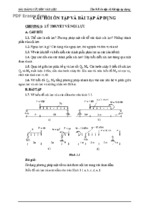
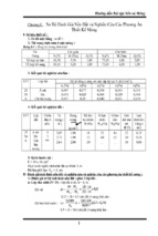
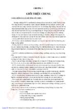
Figure 1.1 shows a frame with 7 degrees of freedom. Note that the
pinned joint at C allows the two members BC and CD to rotate independently, thus giving rise to two freedoms in rotation at the joint.
In structural analysis, the degree of statical indeterminacy is
important, as its value may determine whether the structure
2
3
5
1
4
6
B
C
7
A
FIGURE 1.1. Degrees of freedom of a frame.
D
4 Plastic Analysis and Design of Steel Structures
is globally unstable or stable. If the structure is stable, the degree of
statical indeterminacy is, in general, proportional to the level of complexity for solving the structural problem.
The method described here for determining the degree of statical
indeterminacy of a structure is based on that by Rangasami and
Mallick.6
Only plane frames will be dealt with here, although the method
can be extended to three-dimensional frames.
1.2.1 Degree of Statical Indeterminacy of Frames
For a free member in a plane frame, the number of possible displacements is three: horizontal, vertical, and rotational. If there are n members in the structure, the total number of possible displacements,
denoted by m, before any displacement restraints are considered, is
m ¼ 3n
(1.1)
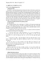
For two members connected at a joint, some or all of the displacements at the joint are common to the two members and these common displacements are considered restraints. In this method for
determining the degree of statical indeterminacy, every joint is considered as imposing r number of restraints if the number of common
displacements between the members is r. The ground or foundation
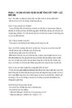
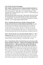
is considered as a noncounting member and has no freedom. Figure 1.2
indicates the value of r for each type of joints or supports in a plane
frame.
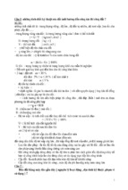
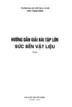
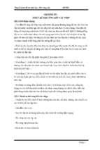
For pinned joints with multiple members, the number of pinned
joints, p, is counted according to Figure 1.3. For example, for a fourmember pinned connection shown in Figure 1.3, a first joint is
counted by considering the connection of two members, a second
joint by the third member, and so on. The total number of pinned
joints for a four-member connection is therefore equal to three. In general, the number of pinned joints connecting n members is p ¼ n – 1.
The same method applies to fixed joints.
r=1
(a) Roller
r=2
(b) Pin
r=3
(c) Fixed
FIGURE 1.2. Restraints of joints.
r=2
(d) Pin
r=3
(e) Rigid ( fixed)
Structural Analysis—Stiffness Method 5
No. of pins, p = 1
No. of pins, p = 2
No. of pins, p = 3
FIGURE 1.3. Method for joint counting.
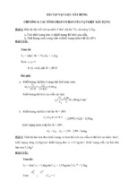
No. of pins, p = 2.5
FIGURE 1.4. Joint counting of a pin with roller support.
For a connection at a roller support, as in the example shown in
Figure 1.4, it can be calculated that p ¼ 2.5 pinned joints and that the
total number of restraints is r ¼ 5.
The degree of statical indeterminacy, fr, of a structure is determined by
X
fr ¼ m À
r
(1.2)
a. If fr ¼ 0, the frame is stable and statically determinate.
b. If fr < 0, the frame is stable and statically indeterminate to the
degree fr.
c. If fr > 0, the frame is unstable.
Note that this method does not examine external instability or
partial collapse of the structure.
Example 1.1 Determine the degree of statical indeterminacy for the
pin-jointed truss shown in Figure 1.5.
(a)
(b)
FIGURE 1.5. Determination of degree of statical indeterminacy in Example 1.1.
6 Plastic Analysis and Design of Steel Structures
Solution. For the truss in Figure 1.5a, number of members n ¼ 3; number of pinned joints p ¼ 4.5.
Hence, fr ¼ 3 Â 3 À 2 Â 4:5 ¼ 0 and the truss is a determinate
structure. For the truss in Figure 1.5b, number of members n ¼ 2;
number of pinned joints p ¼ 3.
Hence, fr ¼ 3 Â 2 À 2 Â 3 ¼ 0 and the truss is a determinate
structure.
Example 1.2 Determine the degree of statical indeterminacy for the
frame with mixed pin and rigid joints shown in Figure 1.6.
C
D
B
E
A
F
FIGURE 1.6. Determination of degree of statical indeterminacy in Example 1.2.
Solution. For this frame, a member is counted as one between two
adjacent joints. Number of members ¼ 6; number of rigid (or fixed)
joints ¼ 5. Note that the joint between DE and EF is a rigid one,
whereas the joint between BE and DEF is a pinned one. Number of
pinned joints ¼ 3.
Hence, fr ¼ 3 Â 6 À 3 Â 5 À 2 Â 3 ¼ À3 and the frame is an indeterminate structure to the degree 3.
1.3 Statically Indeterminate Structures—Direct
Stiffness Method
The spring system shown in Figure 1.7 demonstrates the use of the
stiffness method in its simplest form. The single degree of freedom
structure consists of an object supported by a linear spring obeying
Hooke’s law. For structural analysis, the weight, F, of the object and
the spring constant (or stiffness), K, are usually known. The purpose
Structural Analysis—Stiffness Method 7
K
D
F
FIGURE 1.7. Load supported by linear spring.
of the structural analysis is to find the vertical displacement, D, and
the internal force in the spring, P.
From Hooke’s law,
F ¼ KD
(1.3)
Equation (1.3) is in fact the equilibrium equation of the system.
Hence, the displacement, D, of the object can be obtained by
D ¼ F=K
(1.4)
The displacement, d, of the spring is obviously equal to D. That is,
d¼D
(1.5)
The internal force in the spring, P, can be found by
P ¼ Kd
(1.6)
In this simple example, the procedure for using the stiffness
method is demonstrated through Equations (1.3) to (1.6). For a structure composed of a number of structural members with n degrees of
freedom, the equilibrium of the structure can be described by a number of equations analogous to Equation (1.3). These equations can be
expressed in matrix form as
fFgnÂ1 ¼ ½K nÂn fDgnÂ1
(1.7)
where fFgnÂ1 is the load vector of size ðn  1Þ containing the external
loads, ½K nÂn is the structure stiffness matrix of size ðn  nÞ
corresponding to the spring constant K in a single degree system
shown in Figure 1.7, and fDgnÂ1 is the displacement vector of size
ðn  1Þ containing the unknown displacements at designated locations, usually at the joints of the structure.
8 Plastic Analysis and Design of Steel Structures
The unknown displacement vector can be found by solving
Equation (1.7) as
fDg ¼ ½K À1 fFg
(1.8)
Details of the formation of fFg, ½K, and fDg are given in the following
sections.
1.3.1 Local and Global Coordinate Systems
A framed structure consists of discrete members connected at joints,
which may be pinned or rigid. In a local coordinate system for a member connecting two joints i and j, the member forces and the
corresponding displacements are shown in Figure 1.8, where the axial
forces are acting along the longitudinal axis of the member and the
shear forces are acting perpendicular to its longitudinal axis.
In Figure 1.8, Mi,j, yi,j ¼ bending moments and corresponding
rotations at ends i, j, respectively; Ni,j, ui,j are axial forces and
corresponding axial deformations at ends i, j, respectively; and Qi,j,
vi,j are shear forces and corresponding transverse displacements at
ends i, j, respectively. The directions of the actions and movements
shown in Figure 1.8 are positive when using the stiffness method.
As mentioned in Section 1.2, the freedom codes of a structure are
assigned in its global coordinate system. An example of a member
forming part of the structure with a set of freedom codes (1, 2, 3, 4,
5, 6) at its ends is shown in Figure 1.9. At either end of the member,
the direction in which the member is restrained from movement is
assigned a freedom code “zero,” otherwise a nonzero freedom code is
assigned. The relationship for forces and displacements between local
and global coordinate systems will be established in later sections.
Qj, vj
Mj,
Nj, uj
j
Qi, vi
j
Mi,
Ni, ui
i
i
FIGURE 1.8. Local coordinate system for member forces and displacements.
Structural Analysis—Stiffness Method 9
5
6
j
2
4
3
i
1
FIGURE 1.9. Freedom codes of a member in a global coordinate system.
1.4 Member Stiffness Matrix
The structure stiffness matrix ½K is assembled on the basis of the
equilibrium and compatibility conditions between the members. For
a general frame, the equilibrium matrix equation of a member is
f Pg ¼ ½ K e f dg
(1.9)
where fPg is the member force vector, ½Ke is the member stiffness
matrix, and fdg is the member displacement vector, all in the member’s local coordinate system. The elements of the matrices in Equation (1.9) are given as
9
8
8 9
3
2
0
0 K14
0
0
K11
> Ni >
> ui >
>
>
> >
>Q >
>v >
>
>
> >
6 0
K22 K23
0 K25 K26 7
> i>
> i>
>
>
> >
7
6
=
<
< =
6 0
Mi
K32 K33
0 K35 K36 7
7; fdg ¼ yi
6
; ½Ke ¼ 6
f Pg ¼
0
0 K44
0
0 7
> Nj >
> uj >
>
>
> >
7
6 K41
>
> >
>
> Qj >
> vj >
4 0
K52 K53
0 K55 K56 5
>
>
> >
>
>
> >
;
:
: ;
Mj
yj
0
K62 K63
0 K65 K66
where the elements of fPg and fdg are shown in Figure 1.8.
1.4.1 Derivation of Elements of Member Stiffness Matrix
A member under axial forces Ni and Nj acting at its ends produces
axial displacements ui and uj as shown in Figure 1.10. From the
stress-strain relation, it can be shown that
Ni ¼
Á
EA À
ui Àuj
L
(1.10a)
Nj ¼
Á
EA À
uj Àui
L
(1.10b)