Post-Tensioning Tendon Installation
and Grouting Manual
May 26, 2004
FEDERAL HIGHWAY ADMINISTRATION
POST-TENSIONING TENDON INSTALLATION AND GROUTING MANUAL
5/26/2004
Federal Highway Administration
Post- Tensioning Tendon Installation and Grouting Manual
Preface
This Manual includes state-of-the-art information relative to materials, post-tensioning systems,
construction practices and grouting of post-tensioning tendons for bridges. The Manual is
targeted at Federal, State and local transportation department and private company personnel
that may be involved in the design, inspection, construction or maintenance of bridges that
contain post-tensioning tendons. This Manual will serve as a reference and guide to designers,
inspectors and construction personnel for post-tensioning materials, installation and grouting of
bridge tendons. The document is part of the Federal Highway Administration’s national
technology deployment program and may serve as a training manual.
Preface
1 of 1
FEDERAL HIGHWAY ADMINISTRATION
POST-TENSIONING TENDON INSTALLATION AND GROUTING MANUAL
5/26/2004
Federal Highway Administration
Post-Tensioning Tendon Installation and Grouting Manual
Overall Contents
Overall Contents
List of Figures and Tables
Chapter 1
Introduction
Chapter 2
Post-Tensioning System Materials and Components
Chapter 3
Post-Tensioning Duct and Tendon Installation
Chapter 4
Grouting of Post-Tensioning Tendons
Appendix A
Terminology
Appendix B
Personnel Qualifications
Appendix C
Further Examples of Post-Tensioning Tendon Applications
Appendix D
Corrosion Protection of Post-Tensioning Tendons
Appendix E
Bibliography
Metric Conversion Factors
Overall Contents
1 of 1
FEDERAL HIGHWAY ADMINISTRATION
POST-TENSIONING TENDON INSTALLATION AND GROUTING MANUAL
5/26/2004
Federal Highway Administration
Post-Tensioning Tendon Installation and Grouting Manual
List of Figures and Tables
Chapter 1
Figure 1.1
Figure 1.2
Figure 1.3
Figure 1.4
Figure 1.5
Figure 1.6
Figure 1.7
Figure 1.8
Figure 1.9
Figure 1.10
Figure 1.11
Figure 1.12
Figure 1.13
Figure 1.14
Figure 1.15
Figure 1.16
Figure 1.17
Figure 1.18
Figure 1.19
Figure 1.20
Figure 1.21
Figure 1.22
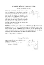
Reinforced concrete beam under load
Comparison of Reinforced and Prestressed Concrete Beams
Typical Post-Tensioning Anchorage Hardware for Strand Tendons
Typical Post-Tensioning Bar System Hardware
Typical Post-Tensioning Bar System Hardware
Cast-In-Place Post-Tensioned Construction in California
Spliced Haunched I-Girder of Main Span Unit
Erection Sequence and Temporary Supports for Spliced I-Girder
Cast-In-Place Segmental Construction using Form Travelers
Foothills Parkway, Tennessee
Precast Segmental Balanced Cantilever Construction
Typical Balanced Cantilever Segment
Bottom Continuity Tendons for Balanced Cantilever Construction
Span-By-Span Construction
Interior Span Post-Tensioning for Span-By-Span Construction
Post-Tensioning in Hammerhead Piers
Post-Tensioning in Straddle Bents
Post-Tensioning in Cantilever Piers
Precast Hollow Segmental Piers, Linn Cove Viaduct, North Carolina
Precast I-Piers
Natchez Trace Parkway Arches, Tennessee
Temporary PT Bars for Segment Erection
Chapter 2
Figure 2.1
Figure 2.2
Figure 2.3
Figure 2.4
Figure 2.5
Figure 2.6
Figure 2.7
Figure 2.8
Figure 2.9
Standard and Modified ASTM C939 Flow Cone Test
Wick Induced Bleed Test
Bleed Under Pressure Test (Gelman Filtration Funnel)
Spiral Wound Steel Duct and Rigid Steel Pipe
Corrugated Plastic Duct
Basic Anchor Plate
Multi-plane Anchor
PT-Bar Anchor Plate
Permanent (Plastic) Grout Cap to Anchor
Table 2.1
Table 2.2
Chapter 3
Figure 3.1
Figure 3.2
Figure 3.3
Figure 3.4
Figure 3.5
Figure 3.6
Permissible Bleed Under Pressure
Physical Properties Required for Shrink Sleeves
Typical Shop Drawing Approval Process for Post-Tensioning
Tendon Profile in Four-Span I-Girder
Calculated Tendon Force after Losses
External Deviated Tendon in End Span
External Tendon Force after Friction and Wedge Set
On-Site Friction Test
List of Figures and Tables
1 of 3
FEDERAL HIGHWAY ADMINISTRATION
POST-TENSIONING TENDON INSTALLATION AND GROUTING MANUAL
5/26/2004
Figure 3.7
Figure 3.8
Figure 3.9
Figure 3.10
Figure 3.11
Figure 3.12
Figure 3.13
Figure 3.14
Figure 3.15
Figure 3.16
Figure 3.17
Figure 3.18
Figure 3.19
Figure 3.20
Figure 3.21
Figure 3.22
Figure 3.23
Figure 3.24
Figure 3.25
Figure 3.26
Figure 3.27
Figure 3.28
Figure 3.29
Figure 3.30
Figure 3.31
Figure 3.32
Figure 3.33
On-Site Bench Test for Modulus of Elasticity
Basic Anchor Bearing Plate
Multi-Plane Anchor
Anchor Plate for PT-Bar
General and Local Anchor Zone in End of I-Girder
Local Zone Reinforcing for Edge Anchor in Thin Slab
Duct Spacing and Clearance in Post-Tensioned Precast Girders
Check Longitudinal and Transverse Duct Alignments
Anchor Recess and Checking of Duct Alignment
Unacceptable Duct Connections and Mistakes
Duct Supports in Post-Tensioned Precast I-Girders
A Possible Result of Poorly Supported and Connected Ducts
Connections for Secondary, Vacuum Grouting, Operations
Unintentional Excess Wobble
Excess Wobble Due to Rebar and Duct Conflict
Duct Size in Post-Tensioned Girders
Placing Concrete in Box Segments
Use of Internal Vibrators for Consolidation of Concrete
Steel Wire Sock for Installing Multi-Strand Tendon
Monostrand Jack
Typical Multi-Strand, Center Hole, Stressing Jack
Prestressing Bar Jack
Jack Calibration
Calibration Chart for Pressure Gauge and Jack Force
Alternate End Stressing
Stresses Along Tendon for Different Modes of Stressing
Anchor Set or Wedge Set
Table 3.1(a)
Table 3.1(b)
Example 1: Elongation of Profiled Tendon in Four-Span Girder (Fig. 3.2)
Example 1 continued: Elongation of Profiled Tendon in Four-Span Girder
(Fig. 3.3)
Example 2: Elongation of External Deviated Tendon in End-Span
(Fig. 3.4)
Stressing Report – Example 1: Profiled Tendon in Four-Span Girder
(Figs. 3.2 and 3.3)
Stressing Report – Example 1 continued: Profiled Tendon in Four-Span
Girder (Figs 3.2 and 3.3)
Table 3.2
Table 3.3(a)
Table 3.3(b)
Chapter 4
Figure 4.1
Figure 4.2
Figure 4.3
Figure 4.4
Figure 4.5
Figure 4.6
Figure 4.7
Figure 4.8
Figure 4.9
Figure 4.10
Figure 4.11
Grout Mixing and Pumping Equipment
Vacuum Grouting Equipment
Grouting Details for a Two-Span Spliced Girder Duct System
Grouting Details for a Four-Span Spliced Girder Duct System
Grouting Details for a Three-Span, Drop-In and Spliced Girder Duct
System
Grouting Details for Cellular Box, Voided or Solid Slab Duct System
Grouting of Cantilever (at Top Continuity) Tendons
Grouting Bottom Continuity Tendons in Variable Depth Box Girders
Grouting Details for End Span, External Tendon
Grouting Vent Locations at Pier Segments in Span-By-Span Bridges
Possible Grout and Drainage Connections for Bottom External Tendons
List of Figures and Tables
2 of 3
FEDERAL HIGHWAY ADMINISTRATION
POST-TENSIONING TENDON INSTALLATION AND GROUTING MANUAL
Figure 4.12
Figure 4.13
Figure 4.14
5/26/2004
Grouting Details for Lateral Tendons in Hammerhead Pier Cap
Grouting and Anchor Details for Vertical Tendons in Piers
Grouting Details and Anchor Protection for Vertical and Lateral Tendons
in C-Pier
Appendix C
Figure C.1
Figure C.2
Figure C.3
Figure C.4
Figure C.5
Figure C.6
Figure C.7
Figure C.8
Figure C.9
Figure C.10
Figure C.11
Figure C.12
Figure C.13
Figure C.14
Cantilever Post-Tensioning Tendons Anchored on End Faces
Cantilever Post-Tensioning Tendons Anchored in Top Blisters
Bottom Continuity Tendons for Balanced Cantilever Construction
Top Continuity Tendons for Balanced Cantilever Construction
Bottom Continuity Tendons Near Expansion Joint at a Support
In-Span Hinges in Balanced Cantilever Construction
Expansion Joint Span Post-Tensioning for Span-By-Span Construction
External/Internal Tendons
Construction of the Linn Cove Viaduct
Transverse Post-Tensioning in the Top Slab of Box Girder
Transverse Post-Tensioning in Diaphragms
Vertical Post-Tensioning in Diaphragms
Transverse Post-Tensioning in Deviation Ribs
Vertical Post-Tensioning in Webs
Appendix D
Figure D.1
Figure D.2
Figure D.3
Figure D.4
Figure D.5
Figure D.6
Figure D.7
Figure D.8
Figure D.9
Figure D.10
Figure D.11
Figure D.12
Figure D.13
Levels of Protection for Corrosion Protection
Levels of Protection to Internal Tendons
Levels of Protection to External Tendons
Sealing of Inlets and Outlets along Internal Tendons
Sealing of Inlets and Outlets along External Tendon
Anchor Protection Details at End Anchorages
Anchor Protection Details at Top Anchorages
Anchor Protection at Interior Piers
Anchor Protection for Cantilever Tendons Anchored in Blisters
Protection of Individual Anchorages at Expansion Joints
Protection of a Group of Anchors at an Expansion Joint Segment
Anchorage Protection at Expansion Joints
Possible Detail for Embedded Face Anchor
List of Figures and Tables
3 of 3
FEDERAL HIGHWAY ADMINISTRATION
POST-TENSIONING TENDON INSTALLATION AND GROUTING MANUAL
5/26/2004
Federal Highway Administration
Post- Tensioning Tendon Installation and Grouting Manual
Chapter 1 - Introduction
Contents
1.1
Objective
1.1.1
1.1.2
1.1.3
1.1.4
1.2
Permanent Post-Tensioned Applications
1.2.1
1.2.2
1.2.3
1.2.4
1.2.5
1.2.6
1.2.7
1.3
Benefits of Post-Tensioning
Principle of Prestressing
Post-Tensioning Operations
Post-Tensioning Systems
Cast-in-Place Bridges on Falsework
Post-Tensioned AASHTO, Bulb-T, and Spliced Girders
Cast-in-Place Segmental Cantilever Bridges
Precast Segmental Balanced Cantilever Bridges
1.2.4.1 Typical Features of Precast Cantilever Segments
1.2.4.2 Cantilever Tendons
1.2.4.3 Continuity Tendons
Precast Segmental Span-by-Span Bridges
Transverse Post-Tensioning of Superstructures
Post-Tensioning of Substructures
1.2.7.1 Hammerhead Piers
1.2.7.2 Straddle Bents
1.2.7.3 Cantilever Piers
1.2.7.4 Precast Piers
1.2.7.5 Precast Segmental Box Section Arches
1.2.7.6 Transverse, Confinement Tendons at Tops of Piers
Temporary Longitudinal Post-Tensioning (Bars) - Typical Applications
1.3.1 Erection of Precast Cantilever Segments
1.3.2 Closure of Epoxy Joints in Span-by-Span Erection
Chapter 1 - Introduction
1 of 19
FEDERAL HIGHWAY ADMINISTRATION
POST-TENSIONING TENDON INSTALLATION AND GROUTING MANUAL
5/26/2004
Chapter 1 - Introduction
1.1
Objective
One of the major advancements in bridge construction in the United States in the second half of
the twentieth century was the development and use of prestressed concrete. Prestressed
concrete bridges, offer a broad range of engineering solutions and a variety of aesthetic
opportunities. The objective of this Manual is to provide guidance to individuals involved in the
installation or inspection of post-tensioning work for post tensioned concrete bridges including
post-tensioning systems, materials, installation and grouting of tendons.
1.1.1
Benefits of Post-Tensioning
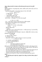
The tensile strength of concrete is only about 10% of its compressive strength. As a result,
plain concrete members are likely to crack when loaded. In order to resist tensile stresses
which plain concrete cannot resist, it can be reinforced with steel reinforcing bars. Reinforcing is
selected assuming that the tensile zone of the concrete carries no load and that tensile stresses
are resisted only by tensile forces in the reinforcing bars. The resulting reinforced concrete
member may crack, but it can effectively carry the design loads (Figure 1.1).
Although cracks occur in reinforced concrete, the cracks are normally very small and uniformly
distributed. However, cracks in reinforced concrete can reduce long-term durability. Introducing
a means of precompressing the tensile zones of concrete members to offset anticipated tensile
stresses reduces or eliminates cracking to produce more durable concrete bridges.
1.1.2
Principle of Prestressing
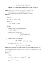
The function of prestressing is to place the concrete structure under compression in those
regions where load causes tensile stress. Tension caused by the load will first have to cancel
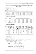
the compression induced by the prestressing before it can crack the concrete. Figure 1.2 (a)
shows a plainly reinforced concrete simple-span beam and fixed cantilever beam cracked under
applied load. Figure 1.2(b) shows the same unloaded beams with prestressing forces applied by
stressing high strength tendons. By placing the prestressing low in the simple-span beam and
high in the cantilever beam, compression is induced in the tension zones; creating upward
camber.
Figure 1.2(c) shows the two prestressed beams after loads have been applied. The loads
cause both the simple-span beam and cantilever beam to deflect down, creating tensile
stresses in the bottom of the simple-span beam and top of the cantilever beam. The Bridge
Chapter 1 - Introduction
2 of 19
FEDERAL HIGHWAY ADMINISTRATION
POST-TENSIONING TENDON INSTALLATION AND GROUTING MANUAL
5/26/2004
Designer balances the effects of load and prestressing in such a way that tension from the
loading is compensated by compression induced by the prestressing. Tension is eliminated
under the combination of the two and tension cracks are prevented. Also, construction
materials (concrete and steel) are used more efficiently ; optimizing materials, construction effort
and cost.
(a) Reinforced concrete
cracked under load.
(b) Post-tensioned
concrete before loading.
(c) Post-tensioned
concrete after loading.
Simply-Supported Beam
Cantilever Beam
Figure 1.2 - Comparison of Reinforced and Prestressed Concrete Beams
Prestressing can be applied to concrete members in two ways, by pretensioning or posttensioning. In pretensioned members the prestressing strands are tensioned against restraining
bulkheads before the concrete is cast. After the concrete has been placed, allowed to harden
and attain sufficient strength, the strands are released and their force is transferred to the
concrete member. Prestressing by post-tensioning involves installing and stressing prestressing
strand or bar tendons only after the concrete has been placed, hardened and attained a
minimum compressive strength for that transfer.
1.1.3
Post-Tensioning Operation
Compressive forces are induced in a concrete structure by tensioning steel tendons of strands
or bars placed in ducts embedded in the concrete. The tendons are installed after the concrete
has been placed and sufficiently cured to a prescribed initial compressive strength. A hydraulic
jack is attached to one or both ends of the tendon and pressurized to a predetermined value
while bearing against the end of the concrete beam. This induces a predetermined force in the
tendon and the tendon elongates elastically under this force. After jacking to the full, required
force, the force in the tendon is transferred from the jack to the end anchorage.
Tendons made up of strands are secured by steel wedges that grip each strand and seat firmly
in a wedge plate. The wedge plate itself carries all the strands and bears on a steel anchorage.
The anchorage may be a simple steel bearing plate or may be a special casting with two or
three concentric bearing surfaces that transfer the tendon force to the concrete. Bar tendons
are usually threaded and anchor by means of spherical nuts that bear against a square or
Chapter 1 - Introduction
3 of 19
FEDERAL HIGHWAY ADMINISTRATION
POST-TENSIONING TENDON INSTALLATION AND GROUTING MANUAL
5/26/2004
rectangular bearing plate cast into the concrete. For an explanation of post-tensioning
terminology and acronyms, see Appendix A.
After stressing, protruding strands or bars of permanent tendons are cut off using an abrasive
disc saw. Flame cutting should not be used as it negatively affects the characteristics of the
prestressing steel. Approximately 20mm (¾ in) of strand is left to protrude from wedges or a
certain minimum bar length is left beyond the nut of a bar anchor. Tendons are then grouted
using a cementitious based grout. This grout is pumped through a grout inlet into the duct by
means of a grout pump. Grouting is done carefully under controlled conditions using grout
outlets to ensure that the duct anchorage and grout caps are completely filled. For final
protection, after grouting, an anchorage may be covered by a cap of high quality grout
contained in a permanent non-metallic and/or concrete pour-back with a durable seal-coat.
Post-tensioning and grouting operations require certain levels of experience, as outlined in
Appendix B.
1.1.4
Post-Tensioning Systems
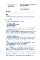
Many proprietary post-tensioning systems are available. Several suppliers produce systems for
tendons made of wires, strands or bars. The most common systems found in bridge
construction are multiple strand systems for permanent post-tensioning tendons and bar
systems for both temporary and permanent situations. Refer to manufacturers’ and suppliers’
literature for details of available systems. Key features of three common systems (multiplestrand and bar tendons) are illustrated in Figures 1.3, 1.4 and 1.5.
Grout injection port
Wedge Plate
Strand
Grout Cap
Duct
Wedges
Trumpet or cone
Anchor plate
Anchor
bearing
area
Grout Cap
Duct
Anchor head
Anchorage
Figure 1.3 - Typical Post-Tensioning Anchorage Hardware for Strand Tendons.
Chapter 1 - Introduction
4 of 19
FEDERAL HIGHWAY ADMINISTRATION
POST-TENSIONING TENDON INSTALLATION AND GROUTING MANUAL
5/26/2004
Figure 1.4 – Typical Post-Tensioning Bar System Hardware.
(Courtesy of Dywidag Systems International)
Figure 1.5 – Typical Post-Tensioning Bar System Hardware
(Courtesy of Williams Form Engineering Corporation)
Chapter 1 - Introduction
5 of 19
FEDERAL HIGHWAY ADMINISTRATION
POST-TENSIONING TENDON INSTALLATION AND GROUTING MANUAL
1.2
Permanent Post-Tensioned Applications
1.2.1
Cast-in-Place Bridges on Falsework
5/26/2004
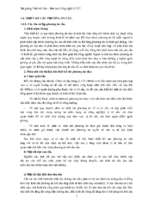
Bridges of this type have a superstructure cross-section of solid or cellular construction.
They are built on-site using formwork supported by temporary falsework (Figure 1.6). Formwork
creates the shape of the concrete section and any internal voids or diaphragms. Reinforcement
and post-tensioning ducts are installed in the forms and then the concrete is placed,
consolidated and cured. When the concrete attains sufficient strength, post-tensioning is
installed and stressed to predetermined forces.
Figure 1.6 – Cast-In-Place Post-Tensioned Construction in California.
Longitudinal post-tensioning typically comprises multi-strand tendons smoothly draped to a
designed profile. In continuous spans, the tendon profile lies in the bottom of the section in the
mid-span region and rises to the top of the section over interior supports. In simple spans and
at the expansion ends of continuous spans, post-tensioning anchors are arranged vertically so
that the resultant of the tendon anchor force passes close to the centroid of the section. A
draped profile of this type provides the most effective distribution of internal prestress for this
type of construction.
1.2.2
Post-Tensioned AASHTO, Bulb-T, and Spliced Girders
Precast, post-tensioned AASHTO and bulb-T girders are usually pre-tensioned sufficiently at the
precast plant to carry their own self weight for transportation to the site and erection. On site,
girders are first erected as simple spans. However, over the interior piers of a three or fourspan unit, they are made continuous by cast-in-place joints that connect the girder ends and
form transverse, reinforced diaphragms.
Post tensioning ducts cast into the webs are spliced through the cast-in-place joints. The ducts
follow a smoothly curved, draped profile along each girder line, rising to the top of the girders
over the interior piers and draping to the bottom flange in mid-span regions. Before the deck
slab is cast, some or all of the tendons running the full length of the multi-span unit are installed
and stressed, making each simple span I-girder into a series of continuous spans. When the
Chapter 1 - Introduction
6 of 19
FEDERAL HIGHWAY ADMINISTRATION
POST-TENSIONING TENDON INSTALLATION AND GROUTING MANUAL
5/26/2004
deck slab has been cast and cured, additional tendons may be installed and stressed on the
fully composite section. Tendons may be anchored in a variety of configurations at the ends of
each continuous unit.
Longer spans can be built using similar techniques. A variable depth girder section
cantilevering over a pier can be spliced to a typical precast girder in the main and side-spans.
An example is shown in Figure 1.7
Figure 1.7 – Spliced Haunched I-Girder of Main Span Unit.
Temporary supports are needed at the splice location in the side spans. The ends of girders
have protruding mild reinforcing to help secure the girder to the closure concrete and ducts that
splice with those of other girder components to accommodate tendons over the full length of the
main unit. The variable depth girder sections are placed over the piers, aligned with the girders
of the side spans, and closures cast. Usually, temporary strong-back beams support the drop-in
girder of the main span while closures are cast.
The sequence for erecting and temporarily supporting this type of I-girder construction is
illustrated in Figure 1.8. After all closures have been cast and have attained the necessary
strength, longitudinal post-tensioning tendons are installed and stressed. To maximize the
efficiency of the post-tensioning, phased stressing is necessary. Some of the longitudinal
tendons are stressed on the I-girder section alone (i.e. while it is non-composite). The
remaining tendons are stressed after the deck slab has been cast and act upon the full
composite section.
Chapter 1 - Introduction
7 of 19
FEDERAL HIGHWAY ADMINISTRATION
POST-TENSIONING TENDON INSTALLATION AND GROUTING MANUAL
5/26/2004
Figure 1.8 - Erection Sequence and Temporary Supports for Spliced I-Girder.
1.2.3
Cast-in-Place Segmental Balanced Cantilever Bridges
An example of cast-in-place balanced cantilever construction using form travelers is shown in
Figure 1.9. Form travelers support the concrete until it has reached a satisfactory strength for
post-tensioning. Longitudinal post-tensioning comprises cantilever tendons in the top slab at
supports and continuity tendons in both top and bottom slabs through the mid-span regions.
Figure 1.9 – Cast-In-Place Segmental Construction using Form Travelers
Chapter 1 - Introduction
8 of 19
FEDERAL HIGHWAY ADMINISTRATION
POST-TENSIONING TENDON INSTALLATION AND GROUTING MANUAL
5/26/2004
Cast-in-place balanced cantilever construction was adopted for four bridges on the Foothills
Parkway in Tennessee designed by the Eastern Federal Lands Division of the Federal Highway
Administration (Figure 1.10).
Figure 1.10 – Foothills Parkway, Tennessee.
1.2.4
Precast Segmental Balanced Cantilever Bridges
Precast segmental balanced cantilever construction involves the symmetrical erection of
segments about a supporting pier. When a segment is lifted into position, adjoining match-cast
faces are coated with epoxy and temporary post-tensioning bars are installed and stressed to
attach the segment to the cantilever. Typically, after a new, balancing segment, is in place on
each end of the cantilever, post-tensioning tendons are installed and stressed from one
segment on one end of the cantilever to its counter-part on the other. Consequently, as
segments are added, more top cantilever tendons are added.
Figure 1.11 – Precast Segmental Balanced Cantilever Construction.
Chapter 1 - Introduction
9 of 19
FEDERAL HIGHWAY ADMINISTRATION
POST-TENSIONING TENDON INSTALLATION AND GROUTING MANUAL
5/26/2004
Figure 1.11 shows two typical methods of placing precast segments in balanced cantilever;
using cranes with stability towers at each pier and using an overhead launching gantry. When
all segments of a new cantilever have been erected and tendons stressed, a closure joint is
made at mid-span. Continuity post-tensioning tendons are installed and stressed through the
closure to make the cantilevers continuous.
1.2.4.1
Typical Features of Precast Cantilever Segments
Top Slab Keys
Cantilever Tendons anchored
on the segment joint face:
“Face Anchored”
Top Temporary PT Bars
Cantilever Tendons anchored in blisters
(Similar blister for continuity tendons but it
would appear reversed in this view)
Bottom Continuity
Anchor Blister
Web Shear Keys
Bottom Continuity Tendons
Bottom Slab Key
Bottom Temporary PT Bars
Figure 1.12 – Typical Balanced Cantilever Segment
Figure 1.12 offers a perspective showing various features of a typical precast cantilever
segment, tendon locations and anchors. These are briefly as follows.
1.2.4.2
Cantilever tendons
Longitudinal post-tensioning tendons for cantilever construction are contained within the top
slab, usually spaced in a single layer over each web. For long spans, a second layer of tendons
in the thickened haunch of the top slab may be required. The layout pattern of the ducts is
always the same at each match-cast joint and ducts shift sideways or up and down within a
segment to make up the full tendon profile from an anchor at one end of the cantilever to that at
the other. Tendons terminate at anchors by a shift of the duct from its row in the slab to an
anchorage. Relative to each segment, cantilever tendons always anchor in the same location.
This may be in the end face of the segment or within an anchor block (or “blister”) on the interior
of the segment.
Chapter 1 - Introduction
10 of 19
FEDERAL HIGHWAY ADMINISTRATION
POST-TENSIONING TENDON INSTALLATION AND GROUTING MANUAL
1.2.4.3
5/26/2004
Continuity Tendons
To complete a span, the ends of two adjacent cantilevers are connected by a cast-in-place
closure at or near mid-span of interior spans. In end spans, the closure joint is usually nearer to
the end expansion joint. When the closure concrete attains sufficient strength, longitudinal posttensioning (continuity) tendons are installed, tensioned and grouted. Figure 1.13 depicts typical
locations and layouts for bottom continuity tendons at mid-span.
Figure 1.13 – Bottom Continuity Tendons for Balanced Cantilever Construction.
Chapter 1 - Introduction
11 of 19
FEDERAL HIGHWAY ADMINISTRATION
POST-TENSIONING TENDON INSTALLATION AND GROUTING MANUAL
1.2.5
5/26/2004
Precast Segmental Span-by-Span Bridges
Span-by-span construction involves the erection of all segments of a span on a temporary
support system with small closure joints cast at one or both ends next to the segments over the
pier. Figure 1.14 shows typical phases for span-by-span construction.
Figure 1.14 – Span-By-Span Construction.
Tendons, usually external, are installed and stressed from the pier segment at one end of the
span to that at the other (Figure 1.15). The tendons drape between the piers, being anchored
near the top of the section over the piers but deviated to the bottom of the section within the
mid-span region.
Chapter 1 - Introduction
12 of 19
FEDERAL HIGHWAY ADMINISTRATION
POST-TENSIONING TENDON INSTALLATION AND GROUTING MANUAL
5/26/2004
Figure 1.15 – Interior Span Post-Tensioning for Span-By-Span Construction.
In order to achieve continuity with the next span, the tendons from one span overlap with the
tendons of the next in the top of the pier segment. At the very ends of each continuous unit, the
ends of the tendons anchor in the diaphragm of the expansion joint segment with anchors
dispersed vertically and approximately parallel to the web of the box.
1.2.6
Transverse Post-Tensioning of Superstructures
For bridge decks, transverse post-tensioning is used in cast-in-place solid slabs and to
transversely connect spans made of precast-prestressed slabs placed side-by-side by means of
narrow cast-in-place longitudinal joints. Transverse post-tensioning is frequently used in deck
slabs of cast-in-place or precast boxes, diaphragms, transverse ribs and similar applications.
For further information and examples, see Appendix C.
1.2.7
Post-Tensioning of Substructures
Substructures for standard AASHTO I-girders, Bulb-T’s, spliced girders, cast-in-place posttensioned and many segmental structures are typically built using reinforced concrete
construction. However, for large bridges or to accommodate other special construction needs,
post-tensioned substructures may be appropriate. Post-tensioned substructures may be used
for bridges of all types of superstructures. Some of the more typical applications are shown in
the following sections.
Chapter 1 - Introduction
13 of 19
- Xem thêm -