5
6
Long
parts
A/B ≤ 3, A/C > 4 Flat
(see note 6)
parts
4
3
L/D > 1.5
(see note 5)
Flat parts
L/D < 0.8
(see note 5)
2
Cubic
parts
Long
cylinders
L/D > 1.5
(see note 5)
1
0
0.8 ≤ L/D ≤ 1.5
(see note 5)
Short
cylinders
Discs
0.8 ≤ L/D ≤ 1.5
(see note 5)
7
8
9
A/B ≤ 3, A/C ≤ 4 Cubic
(see note 6)
parts
Parts are difficult to feed using
conventional hopper feeders (see note 1)
Rectangular
A/B > 3
parts
(see note 6)
(see note 4)
Triangular
or square
prismatic
parts
(see note 3)
Rotational
parts
(see note 2)
L/D < 0.8
(see note 5)
Long
parts
Parts can easily be fed (but not necessarily oriented) using
conventional hopper feeders (see note 1)
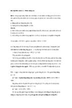
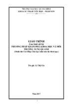
Small Parts for Automatic Handling (Choice of the first digit)
396
Assembly Automation and Product Design
Appendix D
397
Small Parts for Automatic Handling (Choice of the first digit)
1. A first digit of 0-8 is for parts that can be fed easily (but not necessarily
oriented) using conventional vibratory or nonvibratory hopper feeders.
Parts having characteristics making them difficult to feed, irrespective
of basic shape, are assigned a first digit of 9. Difficult-to-feed parts
include those that are flexible, delicate, sticky, light, overlap, large,
very small, nest, severly nest, tanlge, severly tangle or are abrasive.
2. A part whose basic shape is a cylinder or regular prism whose cross
section is a regular polygon of five or more sides is called a rotational
part.
3. A part whose basic shape is a regular prism whose cross section is a
regular polygon of three or four sides is called a triangular or square
part.
4. A part whose basic shape is a regular prism is called a rectangular part.
5. L is the length and D is the diameter of the smallest cylinder that can
completely enclose the part.
6. A is the length of the longest side, C is the length of the shortest side,
and B is the length of the intermediate side of the smallest rectangular
prism that can completely enclose the part.
SECOND DIGIT
Part is ALPHA symmetric
(see note 2)
End surface
Side view
Principal axis
6
7
8
9
BETA symmetric step, chamfer or taper
too small for orientation purposes
Other features, slight asymmetry, features too
small or non-geometric features [such as paint,
lettering, etc.] (see note 8)
5
On end surfaces only
BETA asymmetric features or BETA symmetric
parts with features other than steps, chamfers or
tapers but too small for orientation purposes
(see note 9)
4
On side surface only
3
2
1
0
BETA symmetric hidden features with no
corresponding exposed features
(see note 7)
BETA symmetric
grooves, holes or
recesses
(see note 6)
On both side and
end surfaces
BETA symmetric steps or chamfers on external
surfaces (see note 5)
Part can be fed in a slot supported by large end
or protruding flange with center of mass below
supporting surfaces (see note 4)
End view
Transverse axis
Side surface
Centroid
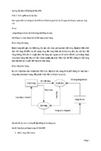
Rotational Parts (Parts with a first digit of 0, 1, or 2)
Part is not ALPHA symmetric
[code the main feature or features, causing ALPHA asymmetry] (see note 3)
0
To be fed
end-to-end
(see note 11)
1
2
3
4
5
Through
grooves
can be seen
in end view
6
On end
surfaces
7
On side
surface
Through grooves cab be
seen in a side view
8
9
Other features,
slight asymmetry, features
Holes or rece- too small or,
sses [cannot non-geometric
be seen in out-features [such
er shape of sil- as paint, letthouette in
ering, etc.]
end views]
BETA asymmetric grooves, holes, recessess
on external surfaces
Part is not BETA symmetric
[code the main feature or features causing BETA asymmetry] (see note 10)
THIRD DIGIT
BETA asymmetric projections
[can be seen in silhouette]
To be fed
side-by-side
On both side
(see note 11) On side
On end
and end
surface only surfaces only
surfaces
Part is BETA symmetric
(see note 9)
398
Assembly Automation and Product Design
Appendix D
399
Rotational Parts (Parts with a first digit of 0, 1, or 2)
1. A rotational part is one whose basic shape is a cylinder or regular prism
having five or more sides. The part is not difficult to feed.
2. The part does not require orientation end to end.
3. A main feature causing ALPHA asymmetry is one defining the endto-end orientation of the part.
4. These are parts that will orient themselves with their principal axis
vertical when placed in a parallel-sided horizontal slot.
5. A BETA-symmetric step or chamfer is a concentric reduction in diameter. The cross section can be circular or any regular polygon of four
or more sides. Discrete projections, recesses or irrelevant features
should be ignored in choosing this digit.
6. The reductions and increases in diameter forming the groove must be
concentric. The cross sections can be circular or any regular polygon
of four or more sides. Discrete projections, recesses or irrelevant features should be ignored in choosing this digit.
7. These parts have an ALPHA-symmetric external shape but their center
of mass is not at the geometric center of the part.
8. If exposed features are prominent but the symmetry caused by these
features is too small to be employed for orienting purposes, then the
symmetry is said to be slight asymmetry.
9. A BETA-symmetric part does not require orientation about its principal
axis.
10. A main feature causing BETA asymmetry is one that completely
defines the orientation of the part about its principal axis.
11. Some parts can only be fed one way. However, when a choice exists,
the technique employed and hence the code can be affected by the
delivery orientation.
400
Assembly Automation and Product Design
Triangular and Square Parts (Parts with a first digit of 3, 4,
or 5)
1. A part whose basic shape is a regular prism whose cross section is an
equilateral triangle or square is called a triangular or square part. The
part is not difficult to feed.
2. Part does not require orientation about its principal axis.
3. A part has rotational symmetry about a specified axis if the part’s
orientation is repeated by rotating it through a certain angle (less than
360 deg) about that axis.
4. When the envelope of a part is a perfect cube, the principal axis should
be selected according to the following priorities:
a. Any axis about which the part is 90 deg rotationally symmetric.
b. An axis about which the part has 180 deg rotational symmetry and
clearly not 90 deg rotational symmetry.
c. An axis about which the part has 180 deg rotational symmetry and
almost 90 deg rotational symmetry.
d. When a part has no rotational symmetry and there is more than one
main feature, the principal axis should be the axis of symmetry of
one of the main features.
When utilizing the above rules and multiple choices still exist, then
the axis that will provide a code with the smallest third digit should
be selected as the principle axis.
5. Part does not require orientation end to end (it has 180 deg rotational
symmetry about at least one transverse axis).
6. A main feature causing ALPHA asymmetry defines the end-to-end
orientation of the part and distinguishes the end and side surfaces.
7. The various aspects of a part resting on a plane are called natural resting
aspects.
8. If exposed features are prominent but the symmetry caused by these
features is too small to be employed for orienting purposes, then the
asymmetry is said to be slight asymmetry. When the part is 180 rotationally symmetric about a certain axis, slight asymmetry implies that
the part is almost 90 deg rotationally symmetric about the same axis.
9. Steps, chamfers or through grooves are features which result in a
deviation of the silhouette of the part from the silhouette of its envelope.
10. These are parts that will orient themselves with their principal axis
vertical when placed in a parallel-sided horizontal slot.
Side surfaces
Side view
Principal axis
Part has 90� or 120� rotational symmetry
about the principal axis
(see notes 2, 3 and 4)
End view
End surfaces
Transverse axis
Centroid
0
0
Part has only
one natural
resting aspect
or end and side
surfaces can be
readily
distinguished
by their shapes
or dimensions
(see note 7)
1
End and side
surfaces can be
distinguished
because of
steps, chamfers,
holes or
recesses
2
End and side
surfaces can
only be distinguished because
of other features, features too
small or slight
asymmetry (see
notes 8 and 12)
Part is ALPHA symmetric
(see note 5)
Triangular and Square Parts (Parts with a first digit of 3, 4, or 5)
3
4
5
6
7
8
Part is not ALPHA symmetric
[code the main feature or features causing ALPHA asymmetry] (see note 6)
Steps or chamfers
Through grooves
(see note 9)
(see note 9)
Part can be fed in Part cannot be
Holes or receslot and support- fed in slot and
sses (cannot
Other
ed by large end or supported by
protruding flang- large end or pr- Can be seen in Can be seen in be seen in outer
geometric
es with center of otruding flanges end view
side view
shape
of
features
mass below supp- with center of
mass below sup- (see note 11) (see note 11)
silhouette)
orting surfaces
and the part is not porting surfaces
or part is
triangular
triangular
(see note 10)
THIRD DIGIT
9
Slight asymmetry, features
too small or
non-geometric
features [such
as paint, lettering, etc.] (see
notes 8 and 12)
Appendix D
401
Part does not
have 180⬚ rotational symmetry
about the principal axis [code
the main feature
or features causing rotational
asymmetry]
(see notes 4
and 14)
Part has 180⬚
rotational symmetry about the
principal axis
[code the main
feature or features causing 180⬚
rather than 90⬚
rotational symmetry about the
principal axis]
(see notes 4
and 13)
End view
End surface
Side view
Principal axis
Non-external
External to the
envelope
Other features, features too
small or slight asymmetry
(see notes 8 and 12)
Holes or recesses
[cannot be seen in outer
shape of silhouette]
Through grooves can be seen
in side or end views
(see note 9)
Steps or
chamfers
can be seen in
side or end views
(see note 9)
Other features, features too small
or slight asymmetry
(see notes 8 and 12)
Holes or recesses
[cannot be seen in outer
shape of silhouette]
Through grooves can be seen
in side or end views (see note 9)
Steps or chamfers can be seen
in side or end views (see note 9)
Transverse axis
Side surface
Centroid
9
8
7
6
5
4
3
2
1
0
1
Code the same feature or
features coded in the
second digit
Steps, chamfers Steps, chamfers
or grooves can or grooves can
be seen in side be seen in end
view or other view or other
features on
features on
side surfaces
end surfaces
(see note 9)
(see note 9)
2
End and side
surfaces can
only be
distinguished
because of
features too
small or slight
asymmetry
(see notes 8
and 12)
Part is ALPHA symmetric
(see note 5)
3
Features on
side surfaces
(see note 15)
4
Features on
end surfaces
(see note 15)
5
Features on
side surfaces
(see note 15)
6
Features on
end surfaces
(see note 15)
Steps or chamfers provided
by non-external features
(see note 9)
7
On side
surfaces
(see note 15)
8
On end
surfaces
(see note 15)
Holes or recesses
[cannot be seen in outer
shape of silhouette]
Part is not ALPHA symmetric
[code the main feature or features causing ALPHA asymmetry] (see note 6)
Steps or chamfers provided
by external features
(see note 9)
Triangular and Square Parts (Parts with a first digit of 3, 4, or 5) (continued)
SECOND DIGIT
9
Other features,
slight asymmetry or features
too small (see
notes 8 and 12)
402
Assembly Automation and Product Design
Appendix D
403
Rectangular Parts (Parts with a first digit of 6, 7, or 8)
1. A part whose basic shape is a rectangular prism is called a rectangular
part. The part is not difficult to feed.
2. 180 deg rotational symmetry about an axis means that the same orientation of the part will be repeated only once by rotating the part
through 180 deg about that axis.
3. Part can be oriented without utilizing features other than the dimensions
of the envelope.
4. Steps, chamfers or through grooves are features which result in a
deviation of the silhouette of a part from the silhouette of its envelope.
5. If exposed features are prominent but the symmetry caused by these
features is too small to be employed for orientation purposes, then the
symmetry is said to be slight asymmetry. For a part with 180 deg
rotational symmetry about a certain axis, slight asymmetry implies that
the part is almost 90 deg rotationally symmetric about the same axis.
6. A feature is too small, if it is too small to be employed for orientation
purposes.
7. A part having no rotational symmetry means that the same orientation
of the part will not be repeated by rotating the part through any angle
less than 360 deg about any one of the three axis X, Y, and Z. The Xaxis is parallel to the longest side of the envelope, the Y-axis is parallel
to the intermediate side and the Z-axis is parallel to the shortest side.
8. A main feature is a feature that is chosen to define the orientation of
the part. All the features that are chosen to completely define the
orientation of the part should be necessary and sufficient for the purpose.
Often, features arise in pairs or groups and the pair or group of features
is symmetric about one of the three axis X, Y, and Z. In this case, the
pair or group of features should be regarded as one feature. Using this
convention, two main features at most are needed to completely define
thed orientation of a part.
9. Sometimes, when a part has no rotational symmetry, its orientation can
either be defined by one or by two main features. Under these circumstances the part code is determined by the following in decreasing order
of preference:
a. Choose one main feature, if it results in a third digit less than 5.
b. Choose two main features if they result in a third digit less than 5.
c. Choose one main feature, if it results in a third digit greater than 5.
d. Choose two main features if they result in a third digit greater than 5.
10. The symmetric plane is the plane that divides the part into halves that
are mirror images of each other.
Y axis
C
Rectangular envelope
B
Part has 180⬚ rotational symmetry about all three axes
(see note 2)
X axis
A
Z axis
0
0
Three adjacent
surfaces of the
envelope have
significant
differences in
dimensions
(see note 3)
1
Parallel to
X axis
Rectangular Parts (Parts with a first digit of 6, 7, or 8)
THIRD DIGIT
2
Parallel to
Y axis
3
Parallel to
Z axis
4
Parallel to
X axis
5
Parallel to
Y axis
6
Parallel to
Z axis
7
Holes or
recesses
(cannot be seen
in outer shape
of silhouette)
8
Slight
asymmetry
or features too
small (see
notes 5 and 6)
Two or more adjacent surfaces of the envelope have similar dimensions
[code the main feature or features which distinguish the adjacent surfaces having similar dimensions]
Steps or chamfers
Through grooves
(see note 4)
(see note 4)
9
Other
geometric
features or
non-geometric
features (such
as paint,
lettering, etc.)
404
Assembly Automation and Product Design
SECOND DIGIT
C
Part’s
orientation
is defined
by one main
feature only
(see note 90
9
8
7
6
5
4
3
About Z axis
Part has a
symmetric
plane
(see note 10)
2
1
About Y axis
About X axis
Rectangular envelope
Y axis
B
Part has no
symmetric
plane
(see note 10)
One
feature is syPart’s
orientation mmetric about X
is defined axis and the othby two main er one is symmetric about Y axis
features and
at least one One feature is syof them is a mmetric about Y
axis and the othstep,
er one is symmechamfer or tric about Z axis
through
One feature is sygroove or a mmetric about Z
group of su- axis and the othch features er one is symme(see note 9) tric about X axis
Part has slight asymmetry about at least one
of its axes or the orientation of the part can only
be defined by two main features neither of
which are steps, chamfers or through grooves
(see notes 5 and 8)
Part has no
slight asymmetry
and its
orientation
can be defined by
one main feature
only or by two
Part has no
main features at
rotational
least one of
symmetry
which is a step,
[code the main chamfer or
feature or
through groove
features that
or group of such
can completely features
define the
(see note 5)
orientation]
(see notes 7
and 8)
Part has 180⬚
rotational
symmetry
about one axis
only (see
note 2)
X axis
A
Z axis
0
Parallel to
X axis
1
Parallel to
Y axis
Steps or chamfers
(see note 4)
2
Parallel to
Z axis
3
Parallel to
X axis
4
Parallel to
Y axis
Through grooves
(see note 4)
5
Parallel to
Z axis
6
Holes or
recesses
[cannot be
seen in outer
shape of
silhouette]
Code the main feature
[code the feature that gives largest third digit, if more than one
feature is utilized to define the orientation of the part] (see note 8)
7
Other
geometric
features
8
9
Non- geometric
Features too
features [such
small
as paint,
(see note 6)
lettering, etc.]
Appendix D
405
406
Assembly Automation and Product Design
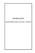
Difficult-to-Feed Parts (parts with a first digit of 9)
Flexible. A part is considered flexible if the part cannot maintain its shape under
the action of automatic feeding so that orienting devices cannot function satisfactorily.
Delicate. A part is considered delicate if damage may occur during handling,
either due to breakage caused by parts falling from orienting sections or tracks
onto the hopper base, or due to wear caused by recirculation of parts in the hopper.
When wear is the criterion, a part would be considered delicate if it could not
recirculate in the hopper for 30 min and maintain the required tolerance.
Sticky. If a force, comparable to the weight of a nontangling or nonnesting part,
is required to separate it from bulk, the part is considered sticky.
Light. A part is considered too light to be handled by conventional hopper feeders
if the ratio of its weight to the volume of its envelope is less than 1.5kN/m3.
Overlap. Parts will tend to overlap in a feeder when an alignment of better than
0.2 mm is required to prevent shingling or overlapping during feeding in single
file on a horizontal track.
Large. A part is considered to be too large to be readily handled by conventional
hopper feeders when its smallest dimension is greater than 50 mm or if its
maximum dimension is greater than 150 mm. A part is considered to be too large
to be handled by a particular vibratory hopper feeder if L > d/8, where L is the
length of the part measured parallel to the feeding direction and d is the feeder
or bowl diameter.
Very small. A part is considered to be too small to be readily handled by
conventional hopper feeders when its largest dimension is less than 3 mm. A part
is considered to be too small to be readily handled by a particular vibratory hopper
feeder if its largest dimension is less than the radius of the curved surface joining
the hopper wall and the track surface measured in a plane perpendicular to the
feeding direction.
Nest. Parts are considered to nest if they interconnect when in bulk causing
orientation problems. No force is required to separate the parts when they are
nested.
Severely nest. Parts are considered to severely nest if they interconnect and lock
when in bulk and require a force to separate them.
Tangle. Parts are said to tangle if a reorientation is required to separate them
when in bulk.
Severely tangle. Parts are said to severely tangle if they require manipulation to
specific orientations and a force is required to separate them.
Abrasive. A part is considered to be abrasive if it may cause damage to the
surface of the hopper feeding device unless these surfaces are specially treated.
407
Appendix D
Difficult-to-Feed Parts (parts with a first digit of 9)
Not
delicate
Delicate
Not
delicate
Parts do not tend to
overlap during feeding
Parts tend to overlap
during feeding
Delicate
Nonflexible
0
Flexible
1
Nonflexible
2
Flexible
3
Nonflexible
4
Flexible
5
Nonflexible
6
Flexible
7
Light
Not light
Light
Not sticky
Sticky
Not sticky
Sticky
Not sticky
Sticky
Not sticky
Sticky
0
1
2
3
4
5
6
7
Very small parts
Rotational parts
For definitions of
these terms and
dimensions see
code sheet −
choice of first
digit
Parts are very small or large but
are non-abrasive
8
9
Incorrect
choice of
first digit
Large parts
Non-rotational parts
Rotational parts
Discs
or short
cylinders
L/D ≤ 1.5
Long
cylinders
L/D > 1.5
Flat
parts
A/B ≤ 3
A/C > 4
Long
parts
A/B > 3
Cubic
parts
A/B ≤ 3
A/B ≤ 4
0
1
2
3
4
Non-rotational parts
Discs
or short
cylinders
L/D ≤ 1.5
Long
cylinders
L/D > 1.5
Flat
parts
A/B ≤ 3
A/C > 4
Long
parts
A/B > 3
Cubic
parts
A/B ≤ 3
A/C ≤ 4
5
6
7
8
9
8
Parts will not severely tangle or nest
Small parts
Part’s orientation is defined by
geometric feature(s) alone
Part’s orientation is defined by
Non-flexible
Parts do not Parts tend geometric
Parts do not Parts tend to
tend
to
overto overlap feature(s)
tend to over- overlap dur- Flexible
lap during
during
alone
lap during
ing feeding
feeding
feeding
feeding
0
Abrasive parts
9
1
2
Very small parts
Large parts
Part’s orientation is not
defined by geometric
feature(s) alone
3
4
5
Part’s orientation is not
defined by
geometric
feature(s)
alone
Part’s orientation is defined by
geometric
feature(s)
alone
6
7
Part’s orientation is not
defined by
geometric
feature(s)
alone
8
Parts will severely
tangle or nest
SECOND DIGIT
Parts are small and non-abrasive
Not light
Parts will severely tangle
Parts will tangle or
nest but not severely
Parts will not tangle or nest
Parts will severely nest but
not severely tangle
THIRD DIGIT
9
408
Assembly Automation and Product Design
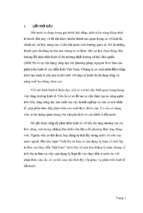
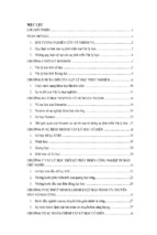
D.2 Feeding and Orienting Techniques
Data sheets showing feeding and orienting techniques catalogued under part
codes.
PART
CODE
REVOLVING HOOK HOPPER FEEDER
d
~ 100
L
0
0
L
Hopper wall
D
Rotational frequency, n
d
A
Revolving hook
A
Section on A-A
Parts delivered per revolution, Np
Stationary base
12
10
8
6
4
Feed rate = Np ⫻ n
16
L/D = 0.
L/D = 0.14
L/D = 0.12
L/D = 0.10
L/D = 0.08
2
0
0
0
0.2
0.4 0.6
0.8 1.0
n
Rotational frequency ratio, n
c
where:
Np = Parts delivered per
revolution
n = Rotational frequency
of hook
nc = Critical rotational
frequency of the hook
(See section D4)
c
E = Efficiency
v = Conveying velocity
v
Feed rate =
D ⫻E
where:
a
b, c
Plan
view
Side
view
L
b
D
0 0 0
0
0.2
0.4
0
0.2
L/D
0.4
0.6
0.8
g = Acceleration due
Parts can be
stacked in the
to gravity (9.81 m/s2)
0.8 discharge hole to
v = 0.1
increase efficiency
gD
0.6
v
= 0.2
gD
1.0
a
Wiper blade*
(Device code 10)
Part orientations
b
Hooded discharge hole*
(Device code 13)
a
Efficiency, E
PART
CODE
0
0.2
0.2
0.4
0.6
0.8
1.0
Return
belt
0.3
0.4
L/D
0.5
X
X
v
d
0.6
0.7
0.8
Part waiting to
be picked up
d ~
50
D
HORIZONTAL BELT FEEDER
Drive shaft
Efficiency, E
VIBRATORY BOWL FEEDER
1.5D
D
v
D ⫻E
Load > 100 parts
v = Main belt velocity
E = Efficiency
D = Part diameter
where:
Feed rate =
L
0 0 1
Section on X-X
Wiper blade
Main belt
PART
CODE
Appendix D
409
Blade
X
X
I
0.3
D
3L
2
0 0
L
I
12
Enlarged section
on X-X
Feed rate
= E � Nt � n
r
I = 0.5
r
PART
CODE
Number of parts fed per reciprocation
E = Efficiency =
Track capacity, Nt
Nt = Track capacity = Maximum number of parts that can fit in track
n = Frequency of blade reciprocation
0.2
Delivery
chute
0
0.05 0.07 0.1
L/D
0.1
0.2
0.3
0.4
Level
of parts
Track
I ~ 50
L
CENTERBOARD HOPPER FEEDER
1
X
I
1.5
2.0
2.5
3.0
Rotary
disc
0.3
d
0.4
0.5
L/D
0.6
t
1
Parts delivered per slot
= Number of slots
n = Rotational frequency of disc
Ns
Np =
where:
Feed rate = Np ⫻ Ns ⫻ n
Enlarged section on X-X
D/4
1.1D
Delivery
chute
L
L/2 < t < L
PART
0 0
CODE
D
Level of parts
d ~ 20; I = 3.5
D
D
Orientation problems
X
Stationary
hopper
ROTARY DISC HOPPER FEEDER
Stationary
plate
Ns slots
Parts delivered per slot, Np
Hopper
Efficiency, E
410
Assembly Automation and Product Design
r
1
0.30
3
5
7
Nb blades
Parts delivered per blade, Np
X
0.35
0.45
L/D
0.40
Delivery chute
X
0.50
I
1.5D
1.1D
45�
Blade
D
0.55
Parts delivered per blade
Nb = Number of blades
n = Rotational frequency
of wheel
Np =
where:
L
0 1
Feed rate = Np � Nb � n
Enlarged view on X-X
0.4 (L + D)
Delivery
chute
Hopper
0.1L
0.6L
0.1L
Level
of parts
Rotational frequency, n
Hopper
r = I ~ 10
D D
PART
0
CODE
X
0
0.2 0.3 0.4
0.5
1.0
1.5
2.0
Reciprocating tube
Stationary hopper
(truncated cone)
0.5 0.6
L/D
0.7 0.8
X
D
w
45�
1.5D
PART
CODE
0
Parts delivered per cycle
n = Frequency of reciprocation
Np =
where:
Feed rate = Np � n
For L/D ≤ 0.5 w = 1.5L
For L/D > 0.5 w = 1.4L
L
0 1
Enlarged section on X-X
45�
Level
of parts
RECIPROCATING TUBE HOPPER FEEDER
Reciprocation frequency, n
Parts delivered per cycle, Np
BLADED WHEEL HOPPER FEEDER
Appendix D
411
n = 0.16 s−1
n = 0.08 s−1
L/D
Section on X-X
40�
0
L
1
Magnet holding capacity is
10−20 times weight of one part.
Np = Parts delivered per magnet
Nm = Number of magnets
n = Frequency of rotation
where:
Feed rate = Np � Nm � n
Rotating disc
D
Agitator
Level of parts
Delivery chute
Rotating disc
d = 30L1/3D2/3
Stationary
hopper
Agitator
Enlarged section on X-X
D
10
d
Y
Y
0
0.2 0.3 0.4 0.5 0.6 0.7
0.5
1.0
1.5
2.0
Magnet
Wiper blade
X
0
0
0.4
0.8
1.2
1.6
0.40
Magnet
Wiper blade
d
L/D
0.45
Rotating disc
0.50
90�
1.5L
L
0 1
Section on X-X
Feed rate = Np � Nm � n
Magnet holding capacity is
10−20 times weight of one part.
Np = Parts delivered per magnet
Nm = Number of magnets
n = Rotational frequency
where:
D
PART
0
CODE
Delivery chute
Level of
parts
Stationary hopper
d = 30L1/3D2/3
MAGNETIC DISC HOPPER FEEDER
Magnet diameter ~ D
Parts delivered per magnet, Np
Agitator
X
PART
CODE
X
MAGNETIC DISC HOPPER FEEDER
X
Magnet diameter ~ D
Parts delivered per magnet, Np
412
Assembly Automation and Product Design
0
0.2
0.4
0.6
0.8
1.0
0
L/D
Feed rate = Np � n
Np = Parts delivered per cycle
n = Rotational frequency
where:
0.7Di
.51D
View on arrow X
1.25D
D
L
0 1
Head of the pin is designed
to accept only one part
Shroud
Pin
Orienting track
0.14 D deep
Orienting track
Feed chute
Path of head of pin
0.8 1.0
Crank
X
0.2 0.4 0.6
Pivot block
Trough
Shroud
Pivot center
Level of parts
Parts delivered per cycle, Np
PART
0
CODE
Di
b
*For devices see section D4
v = Conveying velocity
E = Efficiency
where:
v
⫻E
D
a
Sloped track and ledge*
(device code 25)
Feed rate =
c
D
0 0
L
1
b, c
a
Note: Wiper blade (device code 10)
Required with L/D ≥ 0.7
Plan
view
Side
view
PART
CODE
L/D
0
0.1 0.2 0.3 0.4 0.5 0.6 0.7 0.8
0.2
0.4
0.6
0.8
1.0
Part orientations
a
VIBRATORY BOWL FEEDER
Efficiency, E
ROCKING TROUGH HOPPER FEEDER
Appendix D
413
v
⫻E
D⬘
b reorients to a
*For devices see section D3
v = Conveying velocity
E = Efficiency, E
where:
Feed rate =
c
Part orientations
b
Hooded discharge hole*
(device code 13)
a
Plan
view
Side
view
0
0.2
0.4
0.6
0.8
1.0
c
PART
0 0 2
CODE
D⬘
0.2
5D
⬘
L
0
0.2
0.4
L/D⬘
0.6
v = 0.2
gD⬘
v = 0.1
gD⬘
0.8
g = acceleration due
Parts can be stacked
to gravity (9.81 m/s2)
in the discharge hole
to increase efficiency
Frequency of vibration = 60 Hz
c, d
b
Wiper blade*
(device code 10)
d
Efficiency, E
5D
⬘
0.2
VIBRATORY BOWL FEEDER
Feed rate =
v
⫻E
D
b reorients to a
*For devices see section D3
v = Conveying velocity
E = Efficiency
where:
c
Part orientations
b
d
Hooded discharge hole*
(device code 13)
a
0
0.2
0.4
0.6
0.8
1.0
Plan
view
Side
view
L
c
PART
CODE
D
0 0 5
0
0.2
L/D
0.4
v = 0.2
gD
0.6
0.8
v = 0.1
gD
g = acceleration due
Parts can be stacked
to gravity (9.81 m/s2)
in the discharge hole
to increase efficiency
Frequency of vibration = 60 Hz
c, d
b
Wiper blade*
(device code 10)
VIBRATORY BOWL FEEDER
Efficiency, E
414
Assembly Automation and Product Design
v
⫻E
D
a
d
*For devices see section D3
b
Plan
view
Side
view
0.6
L
D
L/D
0.7
c, d
0.8
0.35D
0 0 6
Wiper blade*
(device code 10)
Portion of b
0
0.5
0.2
0.4
0.6
0.8
1.0
Proportion of b
reorients to a
v = Conveying velocity
E = Efficiency
where:
Feed rate =
c
Part orientations
b
Sloped track and rail*
(device code 24)
a
Efficiency, E
PART
CODE
0
0.3
0.2
0.4
0.6
0.8
1.0
Return belt
0.4
0.5
H/L
0.6
X
X
D1
= 0.5
D
0.7
0.8
0.9
H
D
v
�E
D
Load > 90 parts
v = Main belt velocity
E = Efficiency
D = Part diameter
where:
Feed rate =
L
0 2 1
D1
1.5D
PART
CODE
Section on X-X
Wiper blade
d
Main belt
Part waiting to be
picked up
v
d ~ 50
D
HORIZONTAL BELT FEEDER
L = 0.5
D
Drive shaft
Efficiency, E
VIBRATORY BOWL FEEDER
Appendix D
415
- Xem thêm -