Modular I/O System
PROFIBUS DP
750-343
Manual
Technical description,
installation and
configuration
750-121/050-002
Version 1.0.0
ii •
General
Copyright ã 2002 by WAGO Kontakttechnik GmbH
All rights reserved.
WAGO Kontakttechnik GmbH
Hansastraße 27
D-32423 Minden
Phone: +49 (0) 571/8 87 – 0
Fax:
+49 (0) 571/8 87 – 1 69
E-Mail:
[email protected]
Web:
http://www.wago.com
Technical Support
Phone: +49 (0) 571/8 87 – 5 55
Fax:
+49 (0) 571/8 87 – 85 55
E-Mail:
[email protected]
Every conceivable measure has been taken to ensure the correctness and
completeness of this documentation. However, as errors can never be fully
excluded we would appreciate any information or ideas at any time.
E-Mail:
[email protected]
We wish to point out that the software and hardware terms as well as the
trademarks of companies used and/or mentioned in the present manual are
generally trademark or patent protected.
WAGO-I/O-SYSTEM 750
PROFIBUS
Table of Contents
• iii
TABLE OF CONTENTS
1 Important Comments ................................................................................ 5
1.1
Legal Principles ..................................................................................... 5
1.2
Symbols.................................................................................................. 6
1.3
Font Conventions ................................................................................... 7
1.4
Number Notation ................................................................................... 7
1.5
Safety Notes ........................................................................................... 8
1.6
Scope...................................................................................................... 9
1.7
Abbreviation .......................................................................................... 9
2 The WAGO-I/O-SYSTEM 750............................................................... 10
2.1
System Description .............................................................................. 10
2.2
Technical Data ..................................................................................... 11
2.3
Manufacturing Number........................................................................ 14
2.4
Storage, Assembly and Transport ........................................................ 14
2.5
Mechanical Setup................................................................................. 15
2.6
Power Supply....................................................................................... 23
2.7
Grounding ............................................................................................ 33
2.8
Shielding (Screening)........................................................................... 36
2.9
Assembly Guidelines / Standards ........................................................ 37
3 Fieldbus Coupler...................................................................................... 38
3.1
Fieldbus ECO-Coupler 750-343 .......................................................... 39
4
I/O Modules ............................................................................................ 104
5 PROFIBUS ............................................................................................. 105
5.1
Description......................................................................................... 105
5.2
Wiring ................................................................................................ 106
6
Glossary .................................................................................................. 108
7
Literature list.......................................................................................... 110
WAGO-I/O-SYSTEM 750
PROFIBUS
iv •
Table of Contents
WAGO-I/O-SYSTEM 750
PROFIBUS
Important Comments
Legal Principles
• 5
1 Important Comments
To ensure fast installation and start-up of the units described in this manual,
we strongly recommend that the following information and explanations are
carefully read and abided by.
1.1 Legal Principles
1.1.1 Copyright
This manual is copyrighted, together with all figures and illustrations
contained therein. Any use of this manual which infringes the copyright
provisions stipulated herein, is not permitted. Reproduction, translation and
electronic and photo-technical archiving and amendments require the written
consent of WAGO Kontakttechnik GmbH. Non-observance will entail the
right of claims for damages.
WAGO Kontakttechnik GmbH reserves the right to perform modifications
allowed by technical progress. In case of grant of a patent or legal protection
of utility patents all rights are reserved by WAGO Kontakttechnik GmbH.
Products of other manufacturers are always named without referring to patent
rights. The existence of such rights can therefore not be ruled out.
1.1.2 Personnel Qualification
The use of the product detailed in this manual is exclusively geared to
specialists having qualifications in PLC programming, electrical specialists or
persons instructed by electrical specialists who are also familiar with the valid
standards. WAGO Kontakttechnik GmbH declines all liability resulting from
improper action and damage to WAGO products and third party products due
to non-observance of the information contained in this manual.
1.1.3 Intended Use
For each individual application, the components supplied are to work with a
dedicated hardware and software configuration. Modifications are only
permitted within the framework of the possibilities documented in the
manuals. All other changes to the hardware and/or software and the nonconforming use of the components entail the exclusion of liability on part of
WAGO Kontakttechnik GmbH.
Please direct any requirements pertaining to a modified and/or new hardware
or software configuration directly to WAGO Kontakttechnik GmbH.
WAGO-I/O-SYSTEM 750
PROFIBUS
6 •
Important Comments
Symbols
1.2 Symbols
Danger
Always abide by this information to protect persons from injury.
Warning
Always abide by this information to prevent damage to the device.
Attention
Marginal conditions must always be observed to ensure smooth operation.
ESD (Electrostatic Discharge)
Warning of damage to the components by electrostatic discharge. Observe the
precautionary measure for handling components at risk.
Note
Routines or advice for efficient use of the device and software optimization.
More information
References on additional literature, manuals, data sheets and INTERNET
pages
WAGO-I/O-SYSTEM 750
PROFIBUS
Important Comments
Font Conventions
1.3 Font Conventions
Italic
Names of path and files are marked italic
i.e.:
C:\programs\WAGO-IO-CHECK
Italic
Menu items are marked as bold italic
i.e.:
Save
\
A backslash between two names marks a sequence of
menu items
i.e.:
File\New
END
Press buttons are marked as bold with small capitals
i.e.:
ENTER
<>
Keys are marked bold within angle brackets
i.e.:
Courier
Program code is printed with the font Courier.
i.e.:
END_VAR
1.4 Number Notation
Number Code
Example
Note
Decimal
100
normal notation
Hexadecimal
0x64
C notation
Binary
'100'
'0110.0100'
Within ',
Nibble separated with dots
WAGO-I/O-SYSTEM 750
PROFIBUS
• 7
8 •
Important Comments
Safety Notes
1.5 Safety Notes
Attention
Switch off the system prior to working on bus modules!
In the event of deformed contacts, the module in question is to be replaced, as
its functionality can no longer be ensured on a long-term basis.
The components are not resistant against materials having seeping and
insulating properties. Belonging to this group of materials is: e.g. aerosols,
silicones, triglycerides (found in some hand creams).
If it cannot be ruled out that these materials appear in the component
environment, then additional measures are to be taken:
- installation of the components into an appropriate enclosure
- handling of the components only with clean tools and materials.
Attention
Cleaning of soiled contacts may only be done with ethyl alcohol and leather
cloths. Thereby, the ESD information is to be regarded.
Do not use any contact spray. The spray may impair the functioning of the
contact area.
The WAGO-I/O-SYSTEM 750 and its components are an open system. It
must only be assembled in housings, cabinets or in electrical operation
rooms. Access must only be given via a key or tool to authorized qualified
personnel.
The relevant valid and applicable standards and guidelines concerning the
installation of switch boxes are to be observed.
ESD (Electrostatic Discharge)
The modules are equipped with electronic components that may be destroyed
by electrostatic discharge. When handling the modules, ensure that the
environment (persons, workplace and packing) is well grounded. Avoid
touching conductive components, e.g. gold contacts.
WAGO-I/O-SYSTEM 750
PROFIBUS
Important Comments
Scope
1.6 Scope
This manual describes the field bus independent WAGO-I/O-SYSTEM 750
with the Fieldbus Coupler for PROFIBUS.
Item-No.
Components
750-343
ECO-coupler PROFIBUS 12 MBd
1.7 Abbreviation
AO
Analog Output Module
AI
Analog Input Module
DI
Digital Input
DO
Digital Output
I/O
input/output
ID
Identifier
PFC
Programmable Fieldbus Controller
PFC-PI
Programmable Fieldbus Controller - Process Images
PFC-RTS
Programmable Fieldbus Controller - Running Time System
PI
Process Images
PLC
Programmable Logic Control
RTS
Running Time System
SM
Special Module
WAGO-I/O-SYSTEM 750
PROFIBUS
• 9
10 •
The WAGO-I/O-SYSTEM 750
System Description
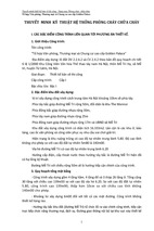
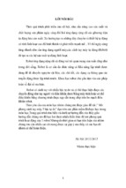
2 The WAGO-I/O-SYSTEM 750
2.1 System Description
The WAGO-I/O-SYSTEM 750 is a modular, fieldbus independent I/O system.
The structure described here consists of an ECO fieldbus coupler (1) and up to
64 connected fieldbus modules (2) for any kind of signal. Together, these
make up the fieldbus node. The end module (3) completes the node.
Fig. 2-1: Fieldbus node
g0xxx14x
ECO couplers for fieldbus systems such as PROFIBUS DP, INTERBUS,
CANopen and DeviceNet are available.
The ECO coupler contains the fieldbus interface, electronics and a power
supply terminal. The fieldbus interface forms the physical interface to the
relevant fieldbus. The electronics process the data of the bus modules and
make it available for the fieldbus communication. The 24 V system supply are
fed in via the integrated power supply terminal.
The fieldbus coupler communicates via the relevant fieldbus.
At first the ECO coupler is concepted for applications with digital I/O
functions. Bus modules for diverse digital and analog I/O functions and
special functions can be connected as well. The communication between the
ECO coupler and the bus modules is carried out via an internal bus.
The WAGO-I/O-SYSTEM 750 has a clear port level with LEDs the status
indication, insertable mini WSB markers and pullout group marker carriers.
The 3-wire technology supplemented by a ground wire connection allows for
direct sensor/actuator wiring.
WAGO-I/O-SYSTEM 750
PROFIBUS
The WAGO-I/O-SYSTEM 750
Technical Data
• 11
2.2 Technical Data
Mechanic
Material
Polycarbonate, Polyamide 6.6
Dimensions Coupler
50 mm x 65* mm x 97 mm
Dimensions I/O module, single
12 mm x 64* mm x 100 mm
Dimensions I/O module, double
24 mm x 64* mm x 100 mm
Installation
on DIN 35 with interlock
modular by
double featherkey-dovetail
Mounting position
any position
Length of entire node
£ 831 mm
Marking
marking label type 247 and 248
paper marking label 8 x 47 mm
Wire range
Wire range
CAGE CLAMP® Connection
0,08 mm² ... 2,5 mm²
AWG 28-14
8 – 9 mm Stripped length
Contacts
Power jumpers contacts
blade/spring contact
self-cleaning
Current via power contacts max
10 A
Voltage drop at Imax
< 1 V/64 modules
Data contacts
slide contact, hard gold plated
1,5µ, self-cleaning
Climatic environmental conditions
Operating temperature
0 °C ... 55 °C
Storage temperature
-20 °C ... +85 °C
Relative humidity
95 % without condensation
Resistance to harmful substances
acc. to IEC 60068-2-42 and IEC 60068-2-43
Special conditions
Ensure that additional measures for components are
taken, which are used in an environment involving:
– dust, caustic vapors or gasses
– ionization radiation.
Mechanical strength
Vibration resistance
acc. to IEC 60068-2-6
Shock resistance
acc. to IEC 60068-2-27
Free fall
acc. to IEC 60068-2-32
≤ 1m (module in original packing)
* from upper edge of DIN 35 rail
WAGO-I/O-SYSTEM 750
PROFIBUS
12 •
The WAGO-I/O-SYSTEM 750
Technical Data
Safe electrical isolation
Air and creepage distance
acc. to IEC 60664-1
Degree of protection
Degree of protection
IP 20
Electromagnetic compatibility*
Directive
Test values
Strength
class
Evaluation
criteria
Immunity to interference acc. to EN 50082-2 (96)
EN 61000-4-2
4kV/8kV
EN 61000-4-3
10V/m 80% AM
EN 61000-4-4
2kV
EN 61000-4-6
10V/m 80% AM
Emission of interference acc. to EN 50081-2 (94)
EN 55011
30 dBµV/m
(2/4)
B
(3)
A
(3/4)
B
(3)
A
Measuring
distance
Class
(30m)
A
37 dBµV/m
Emission of interference acc. to EN 50081-1 (93)
EN 55022
30 dBµV/m
Measuring
distance
Class
(10m)
B
37 dBµV/m
* Exception: 750-630, 750-631
Range of
application
Required specification
emission of interference
Required specification
immunity to interference
Industrial areas
EN 50081-2 : 1993
EN 50082-2 : 1996
Residential areas
EN 50081-1 : 1993
*)
EN 50082-1 : 1992
*) The system meets the requirements on emission of interference in residential areas with
the fieldbus coupler/controller for:
ETHERNET 750-342/-842
LONWORKS 750-319/-819
CANopen
750-337/-837
DeviceNet
750-306/-806
MODBUS
750-312/-314/ -315/ -316
750-812/-814/ -815/ -816
With a special permit, the system can also be implemented with other fieldbus
couplers/controllers in residential areas (housing, commercial and business areas, smallscale enterprises). The special permit can be obtained from an authority or inspection
office. In Germany, the Federal Office for Post and Telecommunications and its branch
offices issues the permit.
It is possible to use other couplers/controllers under certain boundary conditions.
Please contact WAGO Kontakttechnik GmbH.
WAGO-I/O-SYSTEM 750
PROFIBUS
The WAGO-I/O-SYSTEM 750
Technical Data
• 13
Maximum power dissipation of the components
Bus modules
0,8 W / bus terminal (total power dissipation,
system/field)
ECO Fieldbus coupler
2,0 W / coupler
Warning
The power dissipation of all installed components must not exceed the
maximum conductible power of the housing (cabinet).
When dimensioning the housing, care is to be taken that even under high
external temperatures, the temperature inside the housing does not exceed the
permissible ambient temperature of 55 °C.
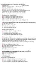
Dimensions
Fig. 2-2: Dimensions
WAGO-I/O-SYSTEM 750
PROFIBUS
g0xxx15e
14 •
The WAGO-I/O-SYSTEM 750
Manufacturing Number
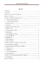
2.3 Manufacturing Number
The manufacturing number is part of the lateral marking on the component.
Fig. 2-3: Manufacturing Number
g01xx09e
The manufacturing number consists of the production week and year, the
software version (if available), the hardware version of the component, the
firmware loader (if available) and further internal information for
WAGO Kontakttechnik GmbH.
The number is also printed on the cover of the configuration interface.
2.4 Storage, Assembly and Transport
Wherever possible, the components are to be stored in their original
packaging. Likewise, the original packaging provides optimal protection
during transport.
When assembling or repacking the components, the contacts must not be
soiled or damaged. The components must be stored and transported in
appropriate containers/packaging. Thereby, the ESD information is to be
regarded.
Statically shielded transport bags with metal coatings are to be used for the
transport of open components for which soiling with amine, amide and
silicone has been ruled out, e.g. 3M 1900E.
WAGO-I/O-SYSTEM 750
PROFIBUS
The WAGO-I/O-SYSTEM 750
Mechanical Setup
• 15
2.5 Mechanical Setup
2.5.1 Installation Position
Along with horizontal and vertical installation, all other installation positions
are allowed.
Attention
In the case of vertical assembly, an end stop has to be mounted as an
additional safeguard against slipping.
WAGO item 249-116 End stop for TS 35, 6 mm wide
WAGO item 249-117 End stop for TS 35, 10 mm wide
2.5.2 Total Expansion
The maximum total expansion of a node is calculated as follows:
Quantity
Width
Components
1
50 mm
ECO coupler
64
12 mm
bus modules
- inputs / outputs
– power supply modules
- etc.
1
12 mm
end module
sum
830 mm
Warning
The maximal total expansion of a node must not exceed 830 mm.
WAGO-I/O-SYSTEM 750
PROFIBUS
16 •
The WAGO-I/O-SYSTEM 750
Mechanical Setup
2.5.3 Assembly onto Carrier Rail
2.5.3.1 Carrier Rail Properties
All system components can be snapped directly onto a carrier rail in
accordance with the European standard EN 50022 (DIN 35).
Warning
WAGO supplies standardized carrier rails that are optimal for use with the
I/O system. If other carrier rails are used, then a technical inspection and
approval of the rail by WAGO Kontakttechnik GmbH should take place.
Carrier rails have different mechanical and electrical properties. For the
optimal system setup on a carrier rail, certain guidelines must be observed:
· The material must be non-corrosive.
· Most components have a contact to the carrier rail to ground electromagnetic disturbances. In order to avoid corrosion, this tin-plated carrier
rail contact must not form a galvanic cell with the material of the carrier
rail which generates a differential voltage above 0.5 V (saline solution of
0.3% at 20°C) .
· The carrier rail must optimally support the EMC measures integrated into
the system and the shielding of the bus module connections.
· A sufficiently stable carrier rail should be selected and, if necessary,
several mounting points (every 20 cm) should be used in order to prevent
bending and twisting (torsion).
· The geometry of the carrier rail must not be altered in order to secure the
safe hold of the components. In particular, when shortening or mounting
the carrier rail, it must not be crushed or bent..
· The base of the I/O components extends into the profile of the carrier rail.
For carrier rails with a height of 7.5 mm, mounting points are to be riveted
under the node in the carrier rail (slotted head captive screws or blind
rivets).
WAGO-I/O-SYSTEM 750
PROFIBUS
The WAGO-I/O-SYSTEM 750
Mechanical Setup
• 17
2.5.3.2 WAGO DIN Rail
WAGO carrier rails meet the electrical and mechanical requirements.
Item Number
Description
210-113 /-112
35 x 7,5; 1 mm; steel yellow chromated; slotted/unslotted
210-114 /-197
35 x 15; 1,5 mm; steel yellow chromated; slotted/unslotted
210-118
35 x 15; 2,3 mm; steel yellow chromated; unslotted
210-198
35 x 15; 2,3 mm; copper; unslotted
210-196
35 x 7,5; 1 mm; aluminum; unslotted
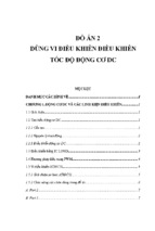
2.5.4 Spacing
The spacing between adjacent components, cable conduits, casing and frame
sides must be maintained for the complete field bus node.
Fig. 2-4: Spacing
g01xx13x
The spacing creates room for heat transfer, installation or wiring. The spacing
to cable conduits also prevents conducted electromagnetic interferences from
influencing the operation.
WAGO-I/O-SYSTEM 750
PROFIBUS
18 •
The WAGO-I/O-SYSTEM 750
Mechanical Setup
2.5.5 Plugging and Removal of the Components
Warning
Before work is done on the components, the voltage supply must be turned
off.
In order to safeguard the ECO coupler from jamming, it should be fixed onto
the carrier rail with the locking disc To do so, push on the upper groove of the
locking disc using a screwdriver.
To pull out the fieldbus coupler/controller, release the locking disc by pressing
on the bottom groove with a screwdriver and then pulling the orange colored
unlocking lug.
Fig. 2-5: Coupler and unlocking lug
g0xxx18e
It is also possible to release an individual I/O module from the unit by pulling
an unlocking lug.
Fig. 2-6: removing bus terminal
p0xxx01x
Danger
Ensure that an interruption of the PE will not result in a condition which
could endanger a person or equipment!
For planning the ring feeding of the ground wire, please see chapter
"Protective Earth".
WAGO-I/O-SYSTEM 750
PROFIBUS
The WAGO-I/O-SYSTEM 750
Mechanical Setup
• 19
2.5.6 Assembly Sequence
All system components can be snapped directly on a carrier rail in accordance
with the European standard EN 50022 (DIN 35).
The reliable positioning and connection is made using a tongue and groove
system. Due to the automatic locking, the individual components are securely
seated on the rail after installing.
Starting with the ECO coupler, the bus modules are assembled adjacent to
each other according to the project planning. Errors in the planning of the node
in terms of the potential groups (connection via the power contacts) are
recognized, as the bus modules with power contacts (male contacts) cannot be
linked to bus modules with fewer power contacts.
Attention
Always link the bus modules with the ECO coupler, and always plug from
above.
Warning
Never plug bus modules from the direction of the end terminal. A ground
wire power contact, which is inserted into a terminal without contacts, e.g. a
4-channel digital input module, has a decreased air and creepage distance to
the neighboring contact in the example DI4.
Always terminate the fieldbus node with an end module (750-600).
WAGO-I/O-SYSTEM 750
PROFIBUS
20 •
The WAGO-I/O-SYSTEM 750
Mechanical Setup
2.5.7 Internal Bus / Data Contacts
Communication between the ECO coupler and the bus modules as well as the
system supply of the bus modules is carried out via the internal bus. It is
comprised of 6 data contacts, which are available as self-cleaning gold spring
contacts.
Fig. 2-7: Data contacts
p0xxx07x
Warning
Do not touch the gold spring contacts on the I/O Modules in order to avoid
soiling or scratching!
ESD (Electrostatic Discharge)
The modules are equipped with electronic components that may be destroyed
by electrostatic discharge. When handling the modules, ensure that the
environment (persons, workplace and packing) is well grounded. Avoid
touching conductive components, e.g. gold contacts.
WAGO-I/O-SYSTEM 750
PROFIBUS