Global Production Engineering and Management
International Master Program
Vietnamese-German University
Report
PROCESS ANALYSIS AND OPTIMIZATION PLAN
of ELECTRONIC DOOR LOCK ASSEMBLY WORKSHOP IN FISCHER ASIA CO., LTD
Class:
GPEM 2016
Module:
Work and Time Study
Lecturer:
Dr.-Ing. Marlene Helfert
Students:
Nguyen Hong Phuc
Vu Đuc
Toe Lattyar Htun
Le Nguyen Dat Long
Binh Duong, November 2016
1
Vietnamese-German University
Work and Time Study
Table of Contents
Introduction and motivation .......................................................................................... 4
1
Measurement .......................................................................................................... 4
1.1
Method ........................................................................................................................ 4
1.2
Result ........................................................................................................................... 5
1.3
Discussions and conclusions ....................................................................................... 12
1.4
Conclusion .................................................................................................................. 13
2
Optimization ......................................................................................................... 13
2.1
Method ...................................................................................................................... 13
2.1.1 Identify current Problems ............................................................................................. 13
2.1.2 Approach and Optimization Process ............................................................................. 13
2.1.3 Optimized Process and New Layout ............................................................................. 15
2.2
Result ......................................................................................................................... 18
2.2.1 Line Balancing ............................................................................................................... 18
2.2.2 Develop New Standard Time and Workstation ............................................................ 18
2.2.3 Productivity: .................................................................................................................. 19
2.3
Discussion .................................................................................................................. 19
2.3.1 Explanation for result .................................................................................................... 19
2.3.2 Improvement and Advantages & practicability (viability) ............................................ 20
2.4
Conclusion .................................................................................................................. 20
Reference ..................................................................................................................... 21
Appendices .................................................................................................................. 22
2
Vietnamese-German University
Work and Time Study
List of Figures
Figure 1-1 Current work layout .......................................................................................................... 6
Figure 1-2 Current Assembly Process in the Factory ......................................................................... 7
Figure 1-3: Actual Processing time in compare with Total Activity Time ........................................ 10
Figure 1-4: Timeshare of Activity Time in each Work Station ......................................................... 10
Figure 1-5: Average processing time of two lines ............................................................................. 11
Figure 1-6: Current Assembly Process in the Factory ...................................................................... 11
Figure 2-1: Pre-assembly Process ..................................................................................................... 14
Figure 3-2: Main Assembly process ................................................................................................... 15
Figure 2-3: Optimized process .......................................................................................................... 16
Figure 2-4: New Layout for optimized process ................................................................................ 17
List of Tables
Table 2-1 REFA sheet Z2 ..................................................................................................................... 8
Table 2-2 Process Studied ................................................................................................................... 8
Table 2-3 Summarize of Work Station .............................................................................................. 9
Table 3-1: Comparison Between Current Condition and Improved Condition ................................. 18
Table 3-2: Main Assembling Process for one Product ..................................................................... 19
Table 3-3: Productivity of Assembly Line Before and After Optimization ........................................ 19
List of Appendices
Appendix 1: Actual activity time in Mainline and Subordinate line ................................................. 22
Appendix 2: Actual Processing time in compare with Total Activity Time and Timeshare of
Individual Activities ................................................................................................................... 23
Appendix 3: Average Processing Time .............................................................................................. 23
Appendix 4: Time categorization in 2 processing lines .................................................................... 24
Appendix 5: REFA sheet for Stopwatch Time Study in Work Stations 1 and 2 ............................... 27
3
Vietnamese-German University
Work and Time Study
Introduction and motivation
Vietnam is currently an attractive investment destiny for international companies. Because of low
labor cost and large available human resource. However, this trend is diminishing because of the
increase salary, inflation and the competition from other developing countries. The only way for
companies to survive in this war is to increase productivity and quality without rise in cost. In
industrialized countries, automation is the most effective way to reach this goal, however it does
not fit Vietnam’s current situation, because of economic, intellectual and political reasons.
From this point of view, stopwatch study and heuristic techniques come as a cheaper and more
applicable solution in assembly industry. An effective optimization plan can help corporates
increase production yield, reduce resources used, in this case time and human force, which then
lead to less production cost, more competitive price and stabler quality, all of which are vital in
this increasingly fierce market.
In this experiment, we measured the processing time in an actual production line in the Fischer
Asia Co., Ltd, who are adapting their production line for a new product, the electronic door lock.
We suggested a new production layout and process, as well as some working settings for a better
work flow and a significant rise in productivity.
1 Measurement
1.1
Method
First, we analyzed the structure of the assembly line and drew the plan of the workshop. The work
process was also recorded. The working conditions including time of day, workshop temperature,
humidity and lighting were measured by using a thermometer and a mobile device.
REFA stopwatch time study [REF-2013] was used for observation, determination, and recording of
the electronic lock assembly at FISCHER company. The resulting information was recorded by using
REFA form. In this form, operational sequences without regular repetitions were not recorded.
Operational sequences with regular repetitions of cyclic sequence were recorded using REFA sheet
Z2. Class members were divided into 6 groups (From group A to F) to record operational sequence.
Group A was in charge of recording operating time at work station 1 and 2.
Through stopwatch time study, the working time of each worker was recorded and categorized
into four types: execution, idle, additional and transport times [HEL-2016]. The data is then
evaluated by using Excel data analysis.
Two characteristics parameters of the process, the throughput time and processing time were
withdrawn from the analysis. [WIL-2007]
Heuristics approach was used for process optimization. All groups observed and recorded the
current process at electric keypad assembly line and propose a solution to optimize the current
process.
4
Vietnamese-German University
1.2
Work and Time Study
Result
The product was a cylindrical electronic door lock with 7 buttons for typing of a passcode, and
only introduced to the company recently. They have already produced a similar product before,
but in different shape (rectangular) size and structure (10 buttons). Workshop
The assembly line is placed is in an 5 x 10 m room. The workshop is air-conditioned. The production
line includes 10 female workers and one male supervisor. The temperature in the workshop was
recorded at 32 degrees C and humidity 68%. There was different lightning condition between work
stations and its brightness varied from 100 lumens (subordinate line) to 210 lumens (main line).
The product is composed of 22 elements, some of which are soldered together.
In pre-assembly stations, the DC motor and circuit board is connected together through two
electrical wires. The motor is then put into a hollow tube (shaft). On one end of the axle of the
motor, a sprocket is installed. It works as a power transmitter between the motor and the slider.
Grease is applied to facilitate the movement of the sprocket. A locking block, which is previously
inserted with a spring, and the slider are added. The circuit board is folded neatly to cover up the
motor.
At the same time, another worker prepares another part of the lock. The main body is the front
cover, on which contains 7 hollow holes. 7 buttons are put into those holes. A plastic grid is
installed to fix those holes in place. The main circuit board, which is soldered with 2 battery
contacting springs before, and the battery holder are successively added. After that, 4 springs are
put into the screw holes on the back of the front cover. Those springs helps preventing the screws
from auto loosening. In final stages, the shaft is put on the front cover, fixed by 4 screws and
covered by a cup.
The product is then put into a laser machine for number marking and the process is finished. At
some stages, the workers might occasionally check their semi-finished or finished products.
5
Vietnamese-German University
Work and Time Study
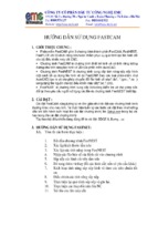
In the workshop, two groups work in parallel. One group (Main Line) includes workers in
workstations 7, 8 and 9, who assemble the front cover, shaft and final product (screwing)
respectively. The same pattern applies to the other group (Subordinate Line) with workstations 4,
3 and 2. Both groups receive the motors soldered the small board from workstation 6, the locking
block from workstation 1, and send assembled products to workstation 10, where the laser
engraving machine marks numbers on the locks. In works station 5, each motor is soldered with
two wires.
1
2
3
4
5
6
Locking
Block
Assembling
Screwing
Shaft
Assembling
Front-Cover
Assembling
Small BoardMotor
Soldering
Wire-Motor
Soldering
11
Testing
10
Laser
Engraving
9
8
7
Screwing
Shaft
Assembling
Front-Cover
Assembling
Figure 1-1 Current work layout
6
Vietnamese-German University
Work and Time Study
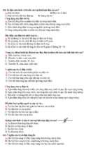
Figure 1-2 Current Assembly Process in the Factory
After recording process by using REFA sheet Z2 (Appendix 5.), all figures of group A are summarize
in a list of process studied (table 2-2) and summarize workstation (table 2-3)
7
Vietnamese-German University
Work and Time Study
Table 1-1 REFA sheet Z2
Table 1-2 Process Studied
Nr
1
Process
Shaft (locking block)
Time/piece
(sec)
Measure
(sec)
C
(%)
Min
value
Work
Station
10.9
Max
value
13.9
12.4
54
11.7
24.25
24
9
22.1
26.4
II
8.96
24
18.1
7.3
10.6
II
46.63
24
6.2
43.7
49.5
II
I
- Reach spring
- Insert Spring into locking
block
- Release locking block
2
Main I (spring)
- Reach housing
- Put spring into shaft
- Release 4th spring
3
Main II (shaft)
- Reach shaft
- Add pre-assembled shaft
onto housing
- Release shaft
4
Main II (screw)
- Reach screw
- Fix Screw
- Release housing
8
Vietnamese-German University
Work and Time Study
Table 1-3 Summarize of Work Station
Workstation I
Activity
Insert spring into locking block
Wait for material
Workstation II
Time
share of
activity
Activity
Time
share of
activity
77%
Put housing in assembly box and
put 4 spring into housing
28,3%
23%
Add pre-assembled shaft
10,4%
Fix 4 Screw
54,3%
Repair misaligned screw
Total share of processing time
Total share of waiting time
Total share of time spent for
getting/searching parts
Total share of time spent for
personal allowance
Total share of time spent for
additional activities
other
77%
23%
7%
93%
0%
0%
0%
0%
0%
0%
7%
0%
0%
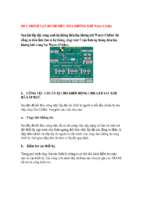
The working time data is represented in three charts below. The first figure compares the actual
processing time and total activity time in 10 workstations. The seconds figure shows the
percentage of each type of times in each workstation. The last one presents the average processing
time of two lines, which is used as data input for optimization.
9
Vietnamese-German University
Work and Time Study
100
85.9
79.9
90
80
74.5
72.5
70
55.4
60
50.7
44
48.4
47.4
50
37.4
40
20
35.4
29
32.7
24.8 22.4
30
16.1
12.4
45.4
20.3
14.3
10
0
1
2
3
4
5
Processing time
6
7
8
9
10
Total Activity Time
Figure 1-3: Actual Processing time in compare with Total Activity Time
100
90
7
23
14.5
9.9
10.3
12.5
80
4
9.3
5.7
21.7
30.3
68.8
60
50
40
3.2
11.3
54.6
70
8.9
93
77
85.5
77.2
2.6
5.5
82
68.4
30
20
86.7
60.9
37.4
28
10
0
1
2
3
4
Execution
5
Idle
6
Additional
7
8
9
10
Transport
Figure 1-4: Timeshare of Activity Time in each Work Station
10
Vietnamese-German University
Work and Time Study
30.5
Laser Engraving
51.7
Final Assembly
45.2
Front Plate Assembly
Shaft Assembly
40.9
12.4
Locking Block Insertion
Motor - Board Soldering
14.3
Wire - Motor Soldering
22.4
Spring - Board Soldering
22.0
0.0
10.0
20.0
30.0
40.0
50.0
60.0
Figure 1-5: Average processing time of two lines
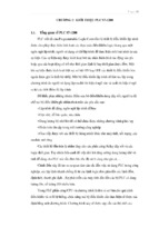
Two characteristic parameters of the process performance are calculated. In the main line,
throughput time is 380.7 seconds, and in subordinate line 364.9 seconds. Processing time of two
lines are 224.3 and 266.3 seconds in the same order.
Pre-assembled
6
Big Board –
Spring Soldering
5
Frontcover
Assembling
Wire – Motor Soldering
Small board – Motor
Soldering
4
7
1
3
8
Put spring to
locking block
Shaft Assembling
2 9
Put 4 springs to
assembled Frontcover
Workstation
Screwing
10
Laser Engraving
Figure 1-6: Current Assembly Process in the Factory
11
Vietnamese-German University
1.3
Work and Time Study
Discussions and conclusions
The data were collected by numerous persons and therefore its quality may varied. However, we
found some consistent trends between measurements of different groups.
Most data have high relative confidence level, between 10% and 20%. Nonetheless, workers who
do single jobs have more stable working trend, with lower confidence level, for example adding
springs to locking block (11.7%), soldering (7.1%) and (4.3%) or laser marking (6.3%), while
sophisticated works require more varied time.
The relative confidence level of some tasks are significantly high, including adding locking block
(16%), slider (15 - 18%), or balancing the shaft on the front cover (16 - 18%), suggesting that those
tasks are more tricky.
The workshop temperature is fairly high, which can significantly affect productivity and stress out
the workers. It is also unevenly lighted. The brightness of work stations was far less than national
standard of lighting requirement for electronic assembly workshops, which is 750 lux [TCV-2008].
One should be cautious that this measurement method may be significantly inaccurate, however,
there is noticeable different lighting condition between two lines. More specifically, there are 2
neon tubes in each work station in main line (work stations 7, 8, 9, 10), whereas the work stations
in the subordinate line are only lighted by ceiling lights.
Generally, most workers their jobs at ease, although some more they find some difficulties with
smaller parts such as springs and sprockets. The springs are especially tricky because they tends
to stuck together and takes time to be untangled.
In both lines, there is a redundant task in which the middle worker has to transfer an element
from one adjacent colleague to another. The worker 8 has to transfer the frontcover from worker
7 to worker 9 and the assembly box the reverse way. Worker 2 also has to transfer locking blocks
from worker 1 to worker 3 after the first one finish a few dozens of them. She might find it difficult
to collect a handful of tiny elements and possibly drop some during conveyance.
The workers in two lines use different tools and do some minor different steps. This can lead to
unbalanced quality and time goal. One worker is equipped with the manual screwdriver and the
other electric one, and this leads to three times difference in execution time (46.6 seconds vs 17.6
seconds per work piece). The latter also check all the buttons after finishing one piece and repair
it instantly if there is a defect.
One significant trend is that workers in main line are faster than those on the subordinate line.
Worker 8 took 29 seconds to finish a shaft, while the time for worker 3 is 47.4 seconds. Worker 9
took only 20.8 seconds to add 4 springs and put the shaft on frontcover, while the other took 33.3
seconds. That is around 50% more quickly of workers 8 and 9, in compare with their colleagues.
12
Vietnamese-German University
Work and Time Study
There’s no major different between worker 7 and 4 in time from put the housing to add battery
holder. However the former’s time is longer because she has to remove the frontcover from a
plastic bag, and check its quality.
We have observed many occasions when workers had to wait for elements supply. Worker 1
waited for material 23% of her time, where worker 6 and 9 did 21.7% and 20% respectively. Worker
5 spent more than half of her time for transportation motors into a storage box, or set up the
motors onto a holding tray, which are non value-added activities. Worker 10 took two-thirds of
her time waiting either for the machine or the next product to come. This suggest that the work
flow is interrupted.
We calculated the average processing time of the two lines, by taking the mean processing time
of the workers that do the same tasks. (i.e., workers 2 and 9, 3 and 8, 4 and 7). We incorporated
quality checking steps from main line, and screwing time of the worker with electronic screwdriver
(work station 9). The highest execution time is found in final assembly station, with 51.7 seconds,
and this time is the decisive speed of the work flow (tact time)
1.4
Conclusion
After collecting those data, we concluded that the working condition for the workers should be
improved. We also suggest an optimization for the process, in which the tasks are shared more
evenly between workers, and some other adjustments to improve productivity
2 Optimization
2.1
2.1.1
Method
Identify current Problems
According to observation in the electronic door lock assembly line, there are 8 workstations by the
overview and each workstation are operating the process with some inefficient workflow such as
waiting time, transportation time and unbalance activities. It can be seen from the data in Figure
1-4, the inadequate positions make workers waste time on getting, searching and transferring
material. Moreover, the executing time of screwing is very high, at 51 seconds per one workpiece;
and while the executing time it makes the worker who use the laser machine to engrave numbers
into locks has to wait for the material. And the waiting time for other activities is also high. This is
the interruption due to dysfunction, lack of material.
2.1.2
Approach and Optimization Process
After doing stopwatch time study in each assembling line, we clarify the working process partly
based on current process, layout. We divide the whole assembly line into three parts: Preassembly, Main-Assembly, and Testingre-Assembling: comprise soldering processes whose cycle
time are small. The worker can operate continuously and efficiently without releasing soldering
torch.
13
Vietnamese-German University
-
-
Work and Time Study
Main-Assembling: comprise processes related to front-cover and shaft assembling. These
processes have many small related steps without unable to separate, so they required a high
activity time.
Testing & Packaging: In this process, the product will be tested by machine and inspected
visually before packaging.
2.1.2.1 Pre-Assembly Line
Pre-Assembly Line includes three sub-process: Wire-Motor Soldering Process, Board-Motor
Soldering Process, Spring-Board Soldering Process. This stage can be seen as the material
preparation for Main Assembly Line. It would be more efficient if the worker only solders boardwire-motor continuously and there is no waiting time. The number of output workpieces is big
enough for Main assembly line
Pre Assembly
t (s)
15
Wire
Motor
Wire-Motor
Soldering
Wire-Motor Small Board t (s)
t (s)
23
22
Board-Wire-Motor
Soldering
Big board
2 Springs
Spring-Big board Soldering
Figure 2-1: Pre-assembly Process
The executing time (te) of soldering process includes the soldering time (tMA) and the personal
allowance time (tP)
te = tMA + tP
[HEL-2016]
The executing time of Wire-Motor Soldering: te1 = 15s
The executing time of Small Board-Wire-Motor Soldering: te2 = 23s
The executing time of Spring-big Board Soldering: te3 = 22s
To increase efficiency, assigning two workers who are responsible for soldering Small circuit board
– Wire – Motor at workstation 1 and 2; one worker for soldering 2-springs-to-big board at
workstation 3.
Because of relatively small processes time, the workers solder components quickly and repeatedly
without releasing solder torch. The number of output workpieces is sufficient high for ensuring
operation in Main Assembly line.
2.1.2.2 Main Assembly Line
Main Assembly Line comprises four sub-processes: Front-Cover Assembling Process, Shaft
Assembling Process, Screwing Process, Laser Engraving Process. The output from Pre-Assembly line
is delivered to Front-cover Assembling process and Shaft Assembling process. According to process
14
Vietnamese-German University
Work and Time Study
time at Measurement in Appendix 4, we detach the possible elements which take big time. Main
assembly line is rearranged and optimized as below:
-
Workstation 4 combines Locking-Block
Assembling
Process
with
Shaft
Assembling Process. In this process,
worker assemble The process time for
one workpiece is the total time of
executing time of shaft assembling and
locking-block assembling. The process
time at Workstation 4:
te4 = 41 + 13 = 54 (s)
-
Workstation 5 combines Front-cover
Assembling Process and Putting 4
springs-to-assembled
front-cover
Process. The executing time for one
workpiece is the total time of frontcover assembling time and time of
putting four spring. The process time at
Workstation 5:
te5 = 44 + 20 = 64 (s)
-
Workstation 6 screws the assembled
shaft into assembled Front cover. Since
this process is no longer including the
step of put 4 springs-to-assembled
Front-cover to workstation 4, the
Pre Assembly
Big Board –
Spring Soldering
1
3
2
Wire – Motor Soldering
Small board – Motor
Soldering
Main Assembly
5 5
Frontcover
Assembling
4
4
13 sec
Put spring to
locking block
44 sec
20 sec
Put 4 springs to
assembled Frontcover
6
31 sec
7
31 sec
8
Shaft Assembling
42 sec
Screwing
Laser Engraving
Workstation
Testing &
Packaging
process time at Workstation 6 is decreased, it is:
Figure 2-2: Main Assembly process
te6 = 31 (s)
-
Workstation 7 is for laser engraving process; its process time cannot be reduced because the
limit of capacity of laser machine. the process time at Workstation 6:
te7 = 31 (s)
Because of high process time, assigning two workers for each workstation 4 and 5 to decrease a
half of the process time for one workpiece assembling.
2.1.3
Optimized Process and New Layout
After rearranging and optimizing activities among workstations for balancing process time and
reducing waiting time. We have a detail optimized process as figure 3-3.
15
Vietnamese-German University
Work and Time Study
Pre Assembly
t (s)
Wire
15
Motor
Wire-Motor Small Board t (s)
t (s)
23
22
Board-Wire-Motor
Soldering
Wire-Motor
Soldering
Big board
2 Springs
Spring-Big board Soldering
Main Assembly
t (s)
13
Add spring to
locking block
Add
locking
block
Check
quality
Add Add Motor Greas Fold
Slider & Sprocket
e
board
Add
buttons
41
Add 4 small Springs
Add preassembled shaft
Fix 4 screws
Check button
Add t (s)
battery
holder
44
Wait for
proceeding
Laser Engraving
t (s)
20
t (s)
31
Screwing
Put in laser
marking machine
Add big
board
Frontcover Assembling
t (s)
Shaft Assembling
Add
support
grid
Take out and end t (s)
process
31
Testing & Packaging
Testing
Packaging
Figure 2-3: Optimized process
Based on current workspace, facilities and manpower (10 persons), we change some workstation
for improving efficient of the material flow as figure 3-4.
The figure explains the process for the making of a complete product. There is a total of 8 stages
with ten workers in the process, beginning with the soldering wire-motor-board and culminating
in the production of the electronic door lock.
To begin, the two wire is soldered to a motor at workstation 1 and then delivered to workstation
2 for soldering to a small board. At workstation 3, a worker solders two springs into a big board.
16
Vietnamese-German University
Work and Time Study
This process is a material preparation for Main assembly line. The output of workstation 2 is
transferred to workstation 4 for adding sprocket, sliders, locking block, grease and assembling into
a shaft, while the workers at workstation 5 receive the workpiece from workstation 3 and assemble
with front-cover. Next, the workpiece output from workstation 4 and 5 is gathered at workstation
6 for screwing. Two workers are assigned for each workstation 4 and 5 to ensure that one
assembled shaft and one assembled front-cover are delivered to screwing workstation every 32
seconds. Eventually, the workpiece output of workstation 6 is engraved by laser machine at
workstation 7 before tested by a worker at workstation 8. As the result, one product is finished in
every 32 seconds.
Work Piece
OUTPUT
Pre-Assembly
1
2
3
Wire-Motor
Soldering
Small BoardMotor
Soldering
Big BoardSpring
Soldering
t = 23s
t = 15s
t = 22s
t = 64s
Main-Assembly
5
t = 54s
t = 64s
Front Plate Assembling
Tranfer
Shaft Assembling
5
4
Work
Piece
INPUT
8
7
6
Testing &
Packaging
Laser
Engraving
Screwing
Shaft
Assembling
t = 31s
t = 54s
t = 31s
4
Figure 2-4: New Layout for optimized process
17
Vietnamese-German University
Work and Time Study
Result
2.2
2.2.1
Line Balancing
After reviewing the collected data from stopwatch time study, we balanced the whole
process flow by adding workforce, changing process flow and delegating process activities. This
balancing can powerfully optimize the current process regarding waste elimination and optimal
cycle times of each workstation.
Table 2-1: Comparison Between Current Condition and Improved Condition
Current Condition
Workstation
Front-cover
Assembling
workstation
Shaft
Assembling
workstation
Screwing
Assembling
workstation
Laser
Engraving
workstation
2.2.2
Time
per
cycle
After Line Balancing
Waiting
time
Share
of
waiting
time
Man
power
32
0
0%
2
1
27
5
18%
2
0%
1
31
1
3%
1
68%
1
31
1
3%
1
Waiting
time
Share of
waiting
time
Man
power
Time
per
cycle
45
7
16%
1
41
11
27%
52
0
31
21
Develop New Standard Time and Workstation
Optimized tact time and leveled production line were developed as a result of optimization after
organizing the process flow and sequences concerning workforce, layout, worker activities and
cycle time. And then, also waiting times are reasonably minimized and generated optimal efficient
and productive flow.
18
Vietnamese-German University
Work and Time Study
40
32
35
Time (s)
31
31
Screwing
Laser Engraving
28
30
25
20
15
10
5
0
Frontcover
Assembling
Shaft Assembling
Table 2-2: Main Assembling Process for one Product
2.2.3
Productivity:
According to our team observation, we set up the tact time base on the Front-Cover Assembly
Process (longest time workstation) that take 32 seconds to produce a workpiece.
Productivity Calculation is carried out by company available working hour per day which is
consider by personal and factual allowance time.
Table 2-3: Productivity of Assembly Line Before and After Optimization
Particular
Working time per day
2.3
2.3.1
Productivity Before
Optimization
28800 sec
Productivity After
Optimization
28800 sec
Activity time per day
25920 sec
25920 sec
Tact time
Waiting time per day
52 sec
23%
32 sec
5,78%
Output Quantity per day
498 products
810 products
Discussion
Explanation for result
Relationship Between Front-cover Assembling & Screwing
The total time for making one piece of Assembled Front-cover by one worker is about 64 seconds.
Moreover, next workstation, Screwing Process only take 31 seconds per worker for finished one
product. So, every 31 seconds, screwing worker can finish one product. However, if using only one
worker in Front-cover Assembling workstation, the Screwing workstation will have to wait for 33
seconds and impossible to make final product continuously. The only way to eliminate its waiting
time is adding one more worker in Front-cover Assembling Workstation and one workpiece will
19
Vietnamese-German University
Work and Time Study
be finished and delivered to Screwing workstation in every 32 seconds. It will be minimized waiting
time for Screwing workstation.
Relationship Between Shaft Assembling & Screwing
The total time for making 1 piece of Assembled Shaft by one worker is about 54 seconds. The cycle
time of next workstation Screwing is only 31 seconds per worker. So, every 31 seconds it will
produce one finished workpiece. However, if assigning only one worker in the previous
workstation, the Screwing workstation will have to wait for 23 seconds and impossible to make
workpiece continuously. That is why the Shaft Assembling work station need to use 2 workers and
then 2 workpieces should be finished by 56 seconds, 27 seconds for one workpiece respectively.
Thus, there is no more waiting time for each workstation.
Relationship Between Screwing & Laser Engraving Machine
Laser Engraving Process is the final work station of Electronic Lock Assembling line. It takes 31
seconds to engraving on product buttons; that means the machine can produce 1 engraved
product for every 31 seconds. In this case, Screwing Workstation can supply the product to Laser
Engraving Workstation on time because it can convey its product by every 31 seconds. There is no
more waiting time for each product as well.
2.3.2
Improvement and Advantages & practicability (viability)
Advantage: Process Optimization based on line balancing is very easy to apply and less operation
cost. The Calculation base on practical measurements from stopwatch time study can provide
benefits in flexibility for any improvements and modifications.
Besides, the reduction of unnecessary motions and transportation can create a comfortable
workplace for workers. Result in the systematic & optimized workflow, waste elimination and
speed up productivity.
Limitation:
-
-
2.4
The optimization is studied for ten workers with, one laser machine, one screwing machine.
Thus, there are some limits about facilities, manpower, and workspace such as limited table,
workers, speed of machine and quantity of machine.
The cycle time of one laser engraving machine cannot be flexible for any raising of product
demand.
Many simulations are required to ensure new process flow and layout can meet the standard
cycle.
The accuracy of time and activity totally depends on the performance rate of workers and
need providing training & performance assessment.
Conclusion
The primary purpose of our report that we executed together with our team is to develop more
efficient process optimization in Electronic Lock Assembling Line of Fisher Co., Ltd.
20
- Xem thêm -