User Manual
Automated SCADA Solutions
Copyright © 2012 by Remsdaq Ltd. All Rights Reserved.
No part of this publication may be reproduced without the prior written permission of Remsdaq Ltd.
USR00207
ISSUE 10
Contact Details
General
Contact Remsdaq Ltd by post, telephone, fax or via the company website:
Remsdaq Ltd, Parkway, Deeside Industrial Park, Deeside, Flintshire,
CH5 2NL, United Kingdom.
Telephone: +44 (0) 1244 286495; Fax: +44 (0) 1244 286496.
www.remsdaq.com.
Customer Services
For technical queries, please contact the customer services team:
E-mail:
[email protected]
Telephone: +44 (0) 1244 286490.
When requesting technical support, please provide the following information:
- product version number
- type of hardware used
- what happened and what was being done when the problem occurred
- details of any attempts made to solve the problem.
Sales
For sales enquiries, please contact the sales team:
E-mail:
[email protected]
Telephone: +44 (0) 1244 286495.
Remsdaq Ltd also has an international network of authorised business partners. The
sales team can provide information on how to contact your authorised business
partner.
USR00207
ISSUE 10
Documentation
To give feedback on Remsdaq’s documentation, please contact the documentation
team:
E-mail:
[email protected]
Telephone: +44 (0) 1244 286495.
Safety Health Environmental & Quality
For any safety, health, environmental or quality assurance issues, please contact the
SHEQ team:
E-mail:
[email protected]
Telephone: +44 (0) 1244 286495.
USR00207
ISSUE 10
USR00207
Contents
Contents
Contact Details................................................................................................................................2
Contents ..........................................................................................................................................4
Issue Number Revision History ....................................................................................................9
1.
Introduction ...........................................................................................................................15
1.1.
About this manual...............................................................................................................................15
nx
nxl
1.2.
Callisto and Callisto documentation set ........................................................................................16
nx
nx
1.3.
View and its relationship with CaSE ..............................................................................................17
1.4.
Overview of IEC61850........................................................................................................................17
1.4.1.
Background.............................................................................................................................17
1.4.2.
Information exchange mechanisms.........................................................................................18
1.4.3.
Logical nodes and logical devices...........................................................................................18
1.5.
Types of configuration files .................................................................................................................19
1.6.
Configuration strategy documented in this manual.............................................................................20
nx
nxl
1.7.
Physical devices, IEDs, and Callisto and Callisto units.................................................................20
1.8.
Description of icons used in figures ....................................................................................................20
2.
Getting Started ......................................................................................................................21
nx
2.1.
Launching CaSE ..............................................................................................................................21
nx
2.2.
CaSE Interface.................................................................................................................................21
2.2.1.
Main features ..........................................................................................................................21
2.2.2.
Menus and buttons..................................................................................................................22
nx
2.3.
Exiting CaSE ....................................................................................................................................24
3.
Creating a Configuration......................................................................................................25
3.1.
Importance of pre-planning.................................................................................................................25
3.2.
Useful resources.................................................................................................................................25
3.3.
Overview of procedure .......................................................................................................................26
3.4.
Issues to consider before starting out.................................................................................................27
3.4.1.
Do I need to create an SLD (single line drawing)?..................................................................27
3.4.2.
What is the best way to create the hardware configuration?...................................................28
3.5.
Stage 1—Prepare new SCD configuration file....................................................................................29
3.5.1.
Opening new configuration file................................................................................................29
3.5.2.
Checking and changing values for system properties .............................................................31
3.5.3.
Adding a substation.................................................................................................................32
3.5.4.
Adding physical devices..........................................................................................................33
nx
3.5.4.1.
Callisto units ...................................................................................................................33
nxl
3.5.4.2.
Callisto units ...................................................................................................................34
3.5.5.
Saving configuration as an SCD file........................................................................................37
3.6.
Stage 2—Draw SLD (single line drawing) ..........................................................................................37
3.7.
Stage 3—Add logical nodes to SLD ...................................................................................................47
3.7.1.
Deciding which logical nodes to add .......................................................................................47
nx
3.7.1.1.
For Callisto units .............................................................................................................47
nxl
3.7.1.2.
For Callisto units.............................................................................................................53
3.7.2.
Marking up a printout of SLD ..................................................................................................55
3.7.3.
Adding logical nodes to equipment items................................................................................56
3.7.4.
Adding logical nodes to bays and voltage levels.....................................................................58
3.8.
Stage 4—Add logical device to SCL tree............................................................................................59
nx
3.8.1.
Callisto units .........................................................................................................................59
Issue 10
CaSEnx (Callistonx Software Editor) User Manual
Page 4 of 342
2012 Remsdaq Ltd
USR00207
Contents
nxl
3.8.2.
Callisto units.........................................................................................................................60
nx
3.9.
Stage 5—Add AC feeders to SCL tree (for Callisto units only) ........................................................61
3.9.1.
General procedure ..................................................................................................................61
3.9.2.
Extra configuration for double busbar setups..........................................................................63
3.9.3.
Accessing a completed Add AC Feeder wizard to edit its values............................................64
3.9.4.
Details of screens in Add AC Feeder wizard...........................................................................64
3.9.4.1.
‘Feeder’ screen..................................................................................................................64
3.9.4.2.
‘Common Voltages’ screen................................................................................................65
3.9.4.3.
‘Inputs’ screen ...................................................................................................................66
3.9.4.4.
‘Measurements’ screen .....................................................................................................67
3.9.4.5.
‘Fault Detection’ screen.....................................................................................................68
3.9.4.6.
‘Overcurrent Protection’ screen 1 ......................................................................................69
3.9.4.7.
‘Overcurrent Protection’ screen 2 ......................................................................................70
3.9.4.8.
‘Overcurrent Protection’ screen 3 ......................................................................................71
3.9.4.9.
‘Voltage Protection’ screen 1.............................................................................................72
3.9.4.10.
‘Voltage Protection’ screen 2.............................................................................................73
3.9.4.11.
‘Sensitive Earth and Transient Earth Protection’ screen....................................................74
3.9.4.12.
‘Analogue Limit Excursions’ screen...................................................................................75
3.9.5.
Adding double busbar functionality manually ..........................................................................76
3.10. Stage 6—Add switchgear to SCL tree ................................................................................................77
nx
3.10.1.
Initial preparations solely for synchro-checking (Callisto units only) .....................................77
3.10.2.
Running Add Switchgear wizard .............................................................................................81
3.10.2.1.
Launching the Add Switchgear wizard ..............................................................................81
3.10.2.2.
Completing the first wizard screen ....................................................................................81
nx
3.10.2.3.
Completing the specialist wizard screen for synchro-checking (Callisto units only)........82
3.10.2.4.
Completing remaining wizard screens...............................................................................86
3.10.2.5.
Extra steps we undertook for the tutorial example.............................................................87
3.11. Stage 7—Add individual logical nodes to SCL tree ............................................................................90
3.11.1.
Overview .................................................................................................................................90
3.11.2.
Creating new logical node types in Data Type Template ........................................................91
3.11.2.1.
Background information.....................................................................................................91
3.11.2.2.
Procedure..........................................................................................................................93
3.11.3.
Adding logical nodes to the logical device...............................................................................97
3.11.4.
Adding external inputs...........................................................................................................101
3.11.4.1.
Background information...................................................................................................101
3.11.4.2.
Procedure........................................................................................................................106
3.12. Stage 8—Associate logical nodes in SLD and SCL tree ..................................................................110
3.13. Stage 9—Specify capability for non-IEC61850 client devices ..........................................................111
3.13.1.
Overview ...............................................................................................................................111
3.13.1.1.
General scenario .............................................................................................................111
3.13.1.2.
Rules and limitations .......................................................................................................111
3.13.1.3.
Overview of classic and enhanced methods for configuration.........................................112
nx
3.13.1.4.
Callisto example............................................................................................................113
nxl
3.13.1.5.
Callisto example ...........................................................................................................115
3.13.2.
Enhanced method .................................................................................................................117
3.13.2.1.
Step 1—Creating client GGIO logical node types............................................................117
3.13.2.2.
Step 2—Adding client application....................................................................................126
3.13.2.3.
Step 3—Adding slave devices.........................................................................................127
3.13.2.4.
Step 4—Adding client GGIO logical nodes......................................................................132
3.13.3.
Classic method......................................................................................................................133
3.13.3.1.
Step 1—Creating client GGIO logical node types............................................................133
3.13.3.2.
Step 2—Adding client application....................................................................................133
3.13.3.3.
Step 3A—Creating bearer ...............................................................................................134
3.13.3.4.
Step 3B—Adding access points ......................................................................................136
3.13.3.5.
Step 3C—Adding slave devices ......................................................................................138
3.13.3.6.
Step 3D—Associating slave devices with bearer ............................................................141
3.13.3.7.
Step 4—Adding client GGIO logical nodes......................................................................143
3.14. Stage 10—Specify server capability .................................................................................................144
3.14.1.
Overview ...............................................................................................................................144
3.14.2.
Adding an IEC61850 server ..................................................................................................144
Issue 10
CaSEnx (Callistonx Software Editor) User Manual
Page 5 of 342
2012 Remsdaq Ltd
USR00207
Contents
3.14.3.
Creating bearers ...................................................................................................................145
3.14.3.1.
Overview .........................................................................................................................145
3.14.3.2.
Modem bearers ...............................................................................................................145
3.14.3.3.
Serial bearers ..................................................................................................................147
3.14.3.4.
Ethernet bearers..............................................................................................................149
3.14.3.5.
Examples for server communications..............................................................................150
3.14.4.
Adding other (non-IEC61850) servers...................................................................................151
3.14.4.1.
Preparations ....................................................................................................................151
3.14.4.2.
Launching Add Server wizard..........................................................................................151
3.14.4.3.
Completing ‘Server Details’ wizard screen ......................................................................152
3.14.4.4.
Completing ‘Counter and Periodic Groups’ wizard screen ..............................................170
3.14.4.5.
Completing ‘Point Selection’ wizard screen.....................................................................173
3.14.4.6.
Completing ‘Bearer Association’ wizard screen...............................................................178
3.14.5.
Example of added servers ....................................................................................................179
3.14.6.
Modifying configuration of added servers..............................................................................180
3.15. Stage 11—Set up communications sub-networks ............................................................................181
3.15.1.
Creating communications sub-networks ...............................................................................181
3.15.2.
Adding physical devices to communications sub-networks...................................................182
3.15.2.1.
For ‘8-MMS’ types of communications sub-network ........................................................182
3.15.2.2.
For ‘PPP’ types of communications sub-network ............................................................186
3.15.2.3.
For ‘Remsdaq’ types of communications sub-network ....................................................187
3.16. Stage 12—Set up IEC61850 data reporting .....................................................................................188
3.16.1.
Overview of scenario.............................................................................................................188
3.16.2.
Ensuring IEC61850 server added to configuration for physical device .................................188
3.16.3.
Setting up datasets ...............................................................................................................189
3.16.3.1.
Setting up datasets for locally sourced data....................................................................189
3.16.3.2.
Setting up datasets for remotely sourced data ................................................................193
3.16.4.
Setting up report control blocks.............................................................................................196
3.17. Stage 13—Save and close the SCD file ...........................................................................................200
4.
Downloading and Uploading Configurations ..................................................................201
nx
4.1.
Downloads and uploads directly through CaSE .............................................................................201
4.1.1.
What types of configuration files does this involve? ..............................................................201
4.1.2.
System Status tab .................................................................................................................201
4.1.3.
Downloading (sending) configurations to physical devices ...................................................202
4.1.4.
Uploading (getting) configurations from physical devices .....................................................205
4.2.
Preparing for downloads via DNP3 file transfer................................................................................207
4.2.1.
For configuration files with option to include logic files..........................................................207
4.2.2.
For logic files only .................................................................................................................210
5.
Miscellaneous Configuration Tasks .................................................................................212
5.1.
Changing default property values for automatically added hardware ...............................................212
5.1.1.
Typical scenario when this is necessary ...............................................................................212
5.1.2.
General procedure ................................................................................................................212
5.1.3.
List of hardware properties....................................................................................................214
nx
5.1.3.1.
Callisto ..........................................................................................................................214
nxl
5.1.3.2.
Callisto units .................................................................................................................220
5.2.
Adding and configuring hardware manually......................................................................................222
5.2.1.
Overview ...............................................................................................................................222
nx
5.2.2.
Adding hardware to Hardware tree (Callisto units) .............................................................222
5.2.2.1.
Getting started.................................................................................................................222
5.2.2.2.
On-board inputs (on base unit)........................................................................................223
5.2.2.3.
On-board outputs (on base unit)......................................................................................224
5.2.2.4.
On-board serial ports (on base unit)................................................................................225
5.2.2.5.
Power supply unit (PSU) .................................................................................................225
5.2.2.6.
DC analogue inputs configured on PSU..........................................................................226
5.2.2.7.
Expansion modules .........................................................................................................227
nxl
5.2.3.
Adding hardware to Hardware Tree (Callisto units)............................................................229
5.2.3.1.
Getting started.................................................................................................................229
Issue 10
CaSEnx (Callistonx Software Editor) User Manual
Page 6 of 342
2012 Remsdaq Ltd
USR00207
Contents
5.2.3.2.
On-board inputs (on base unit)........................................................................................229
5.2.3.3.
On-board outputs (on base unit)......................................................................................229
5.2.3.4.
On-board DC analogue inputs.........................................................................................230
5.2.3.5.
Onboard monitored outputs (on base unit)......................................................................230
5.2.3.6.
Serial ports ......................................................................................................................231
5.2.3.7.
Expansion module...........................................................................................................231
5.2.4.
Associating hardware in Hardware tree with data in SCL tree ..............................................232
5.2.4.1.
Making associations using facilities in SCL tree ..............................................................232
5.2.4.2.
Making associations using facilities in Hardware tree .....................................................234
5.3.
Setting up archiving of point values ..................................................................................................238
5.3.1.
Overview ...............................................................................................................................238
5.3.2.
Supported types of archiving.................................................................................................238
5.3.3.
Archiving available for each point type..................................................................................239
5.3.4.
Configuring archiver ..............................................................................................................240
5.3.4.1.
Preparations at physical device.......................................................................................240
nx
5.3.4.2.
Configuration in CaSE ..................................................................................................240
5.4.
Setting up disturbance recording ......................................................................................................246
5.4.1.
Overview ...............................................................................................................................246
5.4.2.
Initial preparations.................................................................................................................246
5.4.3.
Configuring disturbance recorder ..........................................................................................247
5.4.3.1.
Launching Configure Disturbance Recorder wizard ........................................................247
5.4.3.2.
Completing first wizard screen ........................................................................................247
5.4.3.3.
Completing second wizard screen...................................................................................248
5.4.3.4.
Completing third (final) wizard screen .............................................................................249
5.4.3.5.
Configured disturbance recorder in SCL tree ..................................................................251
5.5.
Using templates................................................................................................................................252
5.5.1.
Overview ...............................................................................................................................252
5.5.2.
Creating templates ................................................................................................................252
5.5.3.
Inserting templates................................................................................................................255
5.6.
Adding general equipment and sub equipment ................................................................................258
5.6.1.
Overview ...............................................................................................................................258
5.6.2.
Procedure .............................................................................................................................259
5.7.
Adding windings and tap changers to power transformers ...............................................................263
6.
Updating Data Type Templates in Configuration Files ...................................................265
7.
Reference Material A: SCL Tree ........................................................................................267
7.1.
‘Header’ section................................................................................................................................267
7.1.1.
Overview ...............................................................................................................................267
7.1.2.
SCL tree elements ................................................................................................................267
7.2.
‘Substation’ section...........................................................................................................................268
7.2.1.
Overview ...............................................................................................................................268
7.2.2.
SCL tree elements ................................................................................................................270
7.3.
‘Physical Device’ section ..................................................................................................................276
7.3.1.
Overview ...............................................................................................................................276
7.3.2.
SCL tree elements ................................................................................................................278
7.3.2.1.
Access points ..................................................................................................................278
7.3.2.2.
Callisto bearers, clients and servers................................................................................285
7.4.
‘Communication’ section...................................................................................................................288
7.4.1.
Overview ...............................................................................................................................288
7.4.2.
SCL tree elements ................................................................................................................289
7.5.
‘Data Type Templates’ section .........................................................................................................292
7.5.1.
Overview ...............................................................................................................................292
7.5.2.
SCL tree elements ................................................................................................................293
7.5.2.1.
Logical node types ..........................................................................................................293
7.5.2.2.
Data object types.............................................................................................................295
7.5.2.3.
Data attribute types .........................................................................................................297
7.5.2.4.
Enumeration types ..........................................................................................................298
Issue 10
CaSEnx (Callistonx Software Editor) User Manual
Page 7 of 342
2012 Remsdaq Ltd
USR00207
8.
Contents
Reference Material B: Hardware........................................................................................300
nx
8.1.
Callisto units...................................................................................................................................300
8.1.1.
Base unit ...............................................................................................................................300
8.1.2.
Digital inputs..........................................................................................................................301
8.1.3.
Digital outputs .......................................................................................................................301
8.1.4.
Actuator Interface expansion module....................................................................................301
8.1.5.
AC analogue inputs...............................................................................................................302
8.1.6.
DC analogue inputs...............................................................................................................302
8.1.7.
Serial communications ..........................................................................................................302
8.1.8.
Ethernet communications......................................................................................................302
8.1.9.
Power supply unit (PSU) .......................................................................................................303
nxl
8.2.
Callisto units ..................................................................................................................................304
8.2.1.
Base unit ...............................................................................................................................304
8.2.2.
Digital inputs..........................................................................................................................304
8.2.3.
Digital outputs (configurable) ................................................................................................305
8.2.4.
Digital outputs (monitored trip/close pairs) ............................................................................305
8.2.5.
DC analogue inputs...............................................................................................................305
8.2.6.
Serial communications ..........................................................................................................305
8.2.7.
Ethernet communications......................................................................................................305
9.
9.1.
9.2.
9.3.
9.4.
9.5.
9.6.
9.7.
9.8.
9.9.
9.10.
9.11.
9.12.
9.13.
9.14.
9.15.
9.16.
9.17.
9.18.
9.19.
9.20.
9.21.
9.22.
9.23.
9.24.
9.25.
9.26.
9.27.
9.28.
9.29.
9.30.
9.31.
9.32.
9.33.
9.34.
9.35.
Reference Material C: Logical Node Types......................................................................306
ACTUATOR – ‘Actuator Interface’ ....................................................................................................306
CILO — ‘Interlocking’........................................................................................................................307
CSWI — ‘Switch Controller’..............................................................................................................307
EGPS — ‘GPS’.................................................................................................................................308
EHKP — ‘Housekeeping for Physical Device’ ..................................................................................309
EHKS — ‘Housekeeping for Server Communications’ .....................................................................310
ELED — ‘LED Override’ ...................................................................................................................310
ELOG — ‘Logic’................................................................................................................................312
GGIO — ‘Generic Process’...............................................................................................................313
LLN0 — ‘Logical Node Zero’.............................................................................................................314
LPHD — ‘Physical Device Information’.............................................................................................314
MHAI — ‘Harmonics’ ........................................................................................................................315
MHAN — ‘Non Phase Related Harmonics’.......................................................................................316
MMTR — ‘Metering’..........................................................................................................................318
MMXN — ‘Non Phase Related Measurement’..................................................................................319
MMXU — ‘Measurement’ .................................................................................................................320
MSQI — ‘Sequence and Imbalance’.................................................................................................321
PSDE — ‘Sensitive Directional Earth Fault’......................................................................................322
PTEF — ‘Transient Earth Fault Direction'.........................................................................................323
PTOC — ‘Time Overcurrent’.............................................................................................................324
PTOV — ‘Overvoltage’ .....................................................................................................................325
PTUV — ‘Undervoltage’ ...................................................................................................................326
PVOC — ‘Voltage Controlled Time Overcurrent’ ..............................................................................327
RADR — ‘Disturbance Recorder Channel Analogue’ .......................................................................328
RALE — ‘Analogue Limit Excursion’.................................................................................................329
RDIR — ‘Directional Element'...........................................................................................................330
RDRE — ‘Disturbance Recorder Function’.......................................................................................331
RSYN — ‘Synchronism Check’.........................................................................................................332
TCTR — ‘Current Transformer’ ........................................................................................................335
TVTR — ‘Voltage Transformer’ ........................................................................................................336
XCBR — ‘Circuit Breaker’.................................................................................................................337
XSWI — ‘Circuit Switch’ ...................................................................................................................338
ZBCH — ‘Battery Charger PSU’ .......................................................................................................339
ZDCP — ‘DC Power Board’..............................................................................................................341
ZDCS — ‘DC Standby PSU’ .............................................................................................................341
Issue 10
CaSEnx (Callistonx Software Editor) User Manual
Page 8 of 342
2012 Remsdaq Ltd
USR00207
Issue Number Revision History
Issue Number Revision History
Issue N
o
Revision Details
Author
Date
th
Issue 1
First formal release of manual
M. E. Block
9 July 08
Issue 2
Rework and expansion of manual in response to feedback
to Issue 1, plus updating to bring it in-line with the
nx
Callisto 1.3.1 release
M. E. Block
20 Nov 09
Issue 3
Section 3.10.4.1: This concerns the table outlining what
external inputs are required. The CSWI entry has been
modified to include the need for an external input to
RSYN.Rel if synchro-checking is involved.
Section 10: This is a new reference section listing the
supported data attributes.
M. E. Block
26 March 10
Issue 4
Section 3.9.2: This includes a description of the expanded
wizard screen for specifying synchro-checking. To
accommodate this extra description, Section 3.9.2 has
been sub-divided into lower-level subsections.
Section 9: The common data classes for all logical nodes
have been updated. For example, the common data class
for 'Mod' has been updated from INC_NX to MOD_NX.
Section 10: The list of data object types has been updated,
for example to include MOD_NX.
Section 11: The 'T' data attribute type has been updated to
'Timestamp' throughout this section.
M. E. Block
13 Sept 10
Issue 5
Addition of PTEF and RDIR logical nodes. This affects
Sections 3.6.1, 3.10.4 (PTEF only) and 11.
M. E. Block
16 Sept 10
Issue 6
Section 3.4: Step marked as ‘Important’ added to alert
users to check, and if necessary change, the defaults for
system properties such as whether or not to have
analogues normalized.
Section 3.6.1: ACTUATOR logical node added to list.
Section 3.8: Completely rewritten to account for the
expansion of the Add AC Feeder wizard.
Section 3.10.3: Expanded to include instructions on how to
add an ACTUATOR logical node (a type of GGIO logical
node).
Section 3.10.4: Updated table of required external inputs.
Section 3.13: Updated to account for new protocol
settings.
Section 3.15: New material added due to inclusion of the
‘PPP’ type of communications sub-network.
Section 6.2: New section added to describe event
archiving.
Section 9: ACTUATOR logical node added; correction to
description of the ‘TmMult’ data object in the PTOC,
PVOC, PTOV and PTUV logical nodes; general
housekeeping throughout to keep this section up-to-date.
M. E. Block
18 Nov 10
Issue 7
General: The manual no longer advocates the second of
the two configuration strategies (creating separate SSD
M. E. Block
4 April 2011
Issue 10
CaSEnx (Callistonx Software Editor) User Manual
th
th
th
th
th
th
Page 9 of 342
2012 Remsdaq Ltd
USR00207
Issue Number Revision History
and ICD files and amalgamating them to create the SCD
file) and as such all mention of this strategy has been
removed. This means that Section 1.1 and 1.6 have been
redrafted, and the old Section 4 has gone. The sole
configuration strategy now is to create SCD files from the
outset, without recourse to SSD and ICD files.
Section 1.2: New section listing other relevant Remsdaq
documents.
Section 1.3: New section outlining the relationship
nx
nx
between CaSE and View .
Section 2.2.2: New menus item (‘Prepare for File Transfer’,
‘Prepare for Logic Transfer’, ‘Upgrade Device’ and ‘Get
Logs from Device’) added to Configuration menu.
Section 3.4: List of system properties has been expanded.
Section 3.9.1: Simplified the steps necessary to prepare
for synchro-checking (by using Add AC Feeder wizard
rather than adding logical nodes individually).
Section 3.12.1: Limitations for clients appended to existing
diagram; plus a new example for clarity.
Section 3.12.1.2: Description of ‘Slave ID’ field corrected
(here and wherever else it appears).
Section 3.12.1.3: Screenshot redone and tables simplified.
Point mappings for Modbus updated to incorporate
Modbus terminology. Description of Modbus fields
improved, again with recourse to Modbus terminology.
Section 3.12.1.5: New section describing how to add
reportable point types individually to an existing ‘client’
GGIO logical node type.
Section 3.13: Overview now includes details of limitations
in server setups.
Section 3.13.1 and 3.13.2.5: Expanded so that they now
show two example scenarios for server setups with failover
bearers.
Section 3.13.2.2: The description for the ‘Scale Analogue
Value’ setting has been changed for both the IEC60807-5101 and IEC60870-5-104 servers. The description for the
‘Common Address’ setting has been changed for the
IEC60870-5-104 server.
Section 5: Now sub-divided into Sections 5.1 and 5.2.
Section 5.1.4: Upload procedure corrected, with it now
being clear that values get updated rather than there being
a file transfer.
Section 5.2: New section describing how to prepare a
configuration for download via DNP3 file transfer.
Section 6.2.2: This now contains details of how to upload
archived events.
Sections 9, 10 and 11: Removed (these contained
reference material relating to logical nodes, data objects
and data attributes, respectively). Their information is now
nx
in the IEC61850 protocol profile document for Callisto ,
which is document number USR00111.
Issue 8
nx
nxl
General: CaSE now supports Callisto units as well as
nx
Callisto units. The manual has been adapted to reflect
this.
Issue 10
CaSEnx (Callistonx Software Editor) User Manual
M. E. Block
th
20 Oct 2011
Page 10 of 342
2012 Remsdaq Ltd
USR00207
Issue Number Revision History
Section 3.2: List of useful resources added.
Section 3.3: Diagram altered so that setting up
communications precedes (IEC61850) data reporting.
Section 3.7.1.1: RADR and RDRE (both of which relate to
disturbance recording), added to list of available logical
nx
nxl
nodes for Callisto . They are not available for Callisto .
Section 3.7.1.1: The facility to enable the dummy control
on the PSU has been moved from the ZBCH, ZDCS and
ZDCP logical nodes and placed in a specialist XCBR
logical node of type ‘XCBR_DUMMY_NX’. A note relating
to this has been added to the content.
Section 3.11.3: There is now just the one type of ‘Actuator’
logical node.
Section 3.13.2.3: More field descriptions added to second
screen of the Add Other wizard, for the DNP3 and
IEC60870-5-101 client protocols. These relate to the
optional new feature for SPC and DPC point types
whereby you can specify separate ‘trip’ and close’ point
numbers (or object addresses).
Section 3.14: This has now been split to draw a distinction
between, on the one hand, the IEC60870-5-101,
IEC60870-5-104 and DNP3 servers, and on the other
hand the IEC61850 server.
Section 3.14.2: This entire section has been updated, with
more detail added.
Section 3.14.2.3: Analog values can now be scaled as
floating point values, with the following consequences. For
the IEC60870-5-101 server, the old ‘Scaled Analogue
Values’ checkbox (in the Common Properties area of the
first wizard screen) is now renamed the ‘Scaled Analog’
field and is a drop-down list of selectable options. The
same is true for the IEC60870-5-104 server, though no
name-change to the field was required. For all the DNP3
servers, the ‘Analogue Input’ field (in the Static Variation
area of the first wizard screen) now has more selectable
options.
Section 3.15: This has been swapped with the (IEC61850)
data reporting section.
Section 3.15.1: Note added to the ‘8-MMS’ procedure to
indicate that this is how to go about adding an IEC61850
server.
Section 3.15.2.1: Note added to indicate that when you
add a physical device to an ‘8-MMS’ type of
nx
communications sub-network, CaSE automatically adds
an IEC61850 server to the physical device.
Section 3.16: This has been swapped with the
communications set up section. Also, emphasis has been
given to this being IEC61850 data reporting and that such
reporting requires an IEC61850 server configured for the
physical device.
Section 3.16.1: Diagram altered.
Section 3.16.2: New step emphasising the need to have
an IEC61850 server in the configuration for the physical
device.
Section 4.2: Expanded now that logic files can be included
Issue 10
CaSEnx (Callistonx Software Editor) User Manual
Page 11 of 342
2012 Remsdaq Ltd
USR00207
Issue Number Revision History
nx
in the compressed file prepared by CaSE .
Section 5.1: New section describing how to change
hardware property values from their defaults. The section
includes a list of property values that has been compiled
from information lifted from Section 8.
Section 5.2: This used to be Section 5.1. In response to
feedback, this section has been rewritten and includes
extra detail.
Section 5.2.2.4: The lead-in title to the procedure (‘To
add...’) has been removed as it misleadingly suggested
nx
that you needed to add the dummy control to the Callisto
hardware specification, whereas it is added automatically
nx
by CaSE .
Section 5.3: Further detail added in response to feedback;
SD cards no longer an option as storage media.
Section 5.3.3.2: Once the storage space is used up, new
records DO NOT overwrite the old (as previously stated).
Instead, the last 20 records are kept.
Section 5.4: A new section explaining how to set up
disturbance recording.
Section 5.5: A new section explaining how to upload the
log files held on a physical device.
Section 7: Updated and revamped to improve its usability.
Section 8: Revamped and simplified, with the explanations
of properties removed to Section 5.1.
Section 9: Re-introduced material describing the supported
logical node types. This material used to be in this manual
(USR00207), but at the last issue was taken out due to its
inclusion, in more detail, in the IEC61850 protocol profile
document (USR00111). We have now reversed that
decision to remove.
Issue 9
nx
General: All figures that include the Callisto Hardware
tree have been edited to have the ‘Dummy Control’ entry
removed.
Section 1.2: Document list updated, principally because of
nx
the new Callisto Operations Manual (USR00112).
Section 2.2.2: New menu items (‘Set Programming Files
Directory’ and ‘Change Network Settings on a Device’)
added to the Tools and Configuration menus, respectively.
Section 3.3: Updated the steps relating to Stages 9 and 10
(specifying client and server capability).
Sections 3.7.1.1 and 3.7.1.2: Improved the descriptions of
XCBR and XSWI to clarify their different roles. Updated
name of EHKP. Added EHKS and ELED. Upgraded
description of dummy control from a note to a dedicated
subsection, and improved this description.
Section 3.9.3.12: ‘Average Time Option’ setting added to
‘Analogue Limit Excursion’.
Section 3:13: Updated to account for an enhanced ‘Add
Slave Device’ wizard. There is now much more detail
included, and also real-world examples.
Section 3.13.2.1: In the field descriptions for the
IEC60870-5-103 client protocol, ‘Generic Identification
Number’ has been split into ‘... Column’ and ‘...Row’.
Issue 10
CaSEnx (Callistonx Software Editor) User Manual
M. E. Block
2
nd
May 2012
Page 12 of 342
2012 Remsdaq Ltd
USR00207
Issue Number Revision History
Section 3.14.1: Graphic updated to include RPI servers.
Section 3.14.2: The old Section 3.14.3 (adding an
IEC61850 server) has been moved here.
Section 3.14.3: More guidelines for bearers involved in
server communications. Note that modem bearers can use
only on-board serial ports.
Section 3.14.4.3: More information given for ‘Scaled
Analogs’ setting (IEC60870-5-101 and IEC60870-5-104)
and ‘Analogue Inputs’ setting (DNP3). New field (‘Enable
Housekeeping’) added to field descriptions for all server
protocols. New fields added to IEC60870-5-104 and DNP3
Server applications, enabling you to limit the IP addresses
to which these server applications can connect.
Sections 3.14.4.5: Note added to description of ‘Reported
Point Selection’ field regarding uniqueness (or otherwise)
of point numbers across point types.
Section 3.14.4: RPI server added to the descriptions of
how to complete the various wizard screens.
Section 3.14.5: Graphic updated to include RPI servers.
Section 5: Subsections relating to dummy control
removed.
Section 5.1.3.1: For a Battery Charger PSU in Charger
mode, (i) more properties added to the configuration to
account for ‘Lithium-Ion’ battery types, and (ii) ‘Disconnect
Time’ property removed.
Section 5.3: General update to reflect changes to the Add
Archiver wizard.
Old Sections 5.3.4 and 5.3.5: These old subsections,
which described how to upload, view and interpret
nx
archived point values, have been removed to the Callisto
Operations Manual (USR00112).
Section 5.4.2: Extra step added if using a memory stick
(this step is to add an entry for the memory stick to the
hardware configuration).
Old Section 5.4.4: This old subsection, which described
how to upload and view disturbance records, has been
nx
removed to the Callisto Operations Manual (USR00112).
Old Section 5.5: This old subsection, which described how
to upload system log files, has been removed to the
nx
Callisto Operations Manual (USR00112).
Section 8: Subsections related to dummy control removed.
Section 9:
ACTUATOR – ActControl description changed.
EHKP – Name changed to ‘Housekeeping for Physical
Device’ to distinguish it from EHKS.
EHKS – New logical node, named ‘Housekeeping for
Server Communications’ to distinguish it from EHKP.
ELED – New logical node named ‘LED Override’.
RALE – AvTmOp added.
MMXN – BusSel added.
MMXU – BusSel added.
RSYN – Descriptions for SeqCheck and ZeroClose
corrected.
XCBR – Description improved so as to clarify different
roles of XCBR and XSWI; UncmdOp added; Loc removed.
XSWI – Description improved so as to clarify roles of
Issue 10
CaSEnx (Callistonx Software Editor) User Manual
Page 13 of 342
2012 Remsdaq Ltd
USR00207
Issue Number Revision History
XSWI and XCBR; UncmdOp added.
ZBCH – DummyCtrl removed.
ZDCP – DummyCtrl removed.
ZDCS – DummyCtrl removed and PSUEarthed replaced
with MainsHealthy.
Issue 10
Section 3.9.2: New advisory section relating to double
busbars.
Section 3.9.4.1: The Add AC Feeder wizard now supports
double busbars and the ‘Feeder’ screen has been updated
accordingly.
Section 3.9.4.3: Addition of ‘Bus’ column to ‘Inputs’ screen,
to account for setups with both single and double busbars.
Section 3.9.4.6: ‘Trigger Type’ field renamed to ‘Trigger’
field. ‘TmACrv’ column now has the entry ‘IEC Definite
Time’.
Sections 3.9.4.8, 3.9.4.9 and 3.9.4.10: As for Section
3.9.4.6.
Section 3.9.5: New section explaining how to add the new
double busbar functionality manually, to an existing
configuration.
Section 3.10.2.3: Note (regarding double busbars) added
to explanation of how to specify line-side and bus-side
voltages.
Section 3.14.4.3: The DNP3 Server application has three
new fields in its ‘Server Details’ screen: (i) ‘Disable self
addressing’ and ‘Keep alive timeout’ in the Data Link group
of fields, and (ii) ‘Include control output states and/or
analog output states, in requests for all data’ in the
Application group of fields.
Section 9:
TVTR – Bus added.
Issue 10
CaSEnx (Callistonx Software Editor) User Manual
M. E. Block
th
27 Sept 2012
Page 14 of 342
2012 Remsdaq Ltd
USR00207
Section 1: Introduction
1.
1.1.
Introduction
About this manual
This manual explains how to use the Callistonx Software Editor (CaSEnx) to create
IEC61850-based configurations for use in both Callistonx and Callistonxl units.
Section 1 (this section) introduces the manual, describing its structure and giving
background information such as an overview of IEC61850 and the types of
configuration files it supports.
Sections 2 to 6 contain task-based material:
Section 2 explains the basics of CaSEnx, such as how to launch the product and
a description of its interface.
Section 3 explains how to create a downloadable configuration (an SCD file).
Section 4 explains how to download (‘send’) configurations from the PC hosting
CaSEnx to Callistonx and Callistonxl units, and how to upload (‘get’) configurations
in the reverse direction.
Section 5 explains how to perform a number of miscellaneous configuration
tasks, such as configuring hardware manually and using templates.
Section 6 explains how to update the Data Type Template in a configuration file
so that it is coherent with the latest ‘default’ Data Type Template created by
Remsdaq and which ships with each new release of the software.
Sections 7 to 9 contain reference material, as follows:
Section 7 describes the elements of the SCL tree.
Section 8 describes the hardware aspects of Callistonx and Callistonxl units.
Section 9 describes the logical node types available for Callistonx and Callistonxl.
Issue 10
CaSEnx (Callistonx Software Editor) User Manual
Page 15 of 342
2012 Remsdaq Ltd
USR00207
Section 1: Introduction
1.2.
Callistonx and Callistonxl documentation set
Document
Reference
Title
INS00107
Callisto Installation Manual
INS00211
Callisto
OPD00107
Callisto /Callisto
USR00207
CaSE User Manual (this manual)
USR00707
Description
nx
nxl
nx
Installation Manual
nxl
Reference Manual
nx
1
nx
Instructions for installing Callisto
nx
Instructions for installing Callisto
nxl
Background reference material for Callisto
nxl
and Callisto , such as their technical
specifications and system architecture
nx
nx
nx
CaSE (the Callisto Software Editor) is the
tool you use to create IEC61850-based
nx
nxl
configurations for use in Callisto and Callisto
units
nx
View User Manual
View is a web-based tool hosted on the
nx
nxl
Callisto or Callisto unit and accessible via a
web browser on a connected PC. It provides a
quick and easy way for you to monitor and
configure the day-to-day operation of a
nx
nxl
Callisto or Callisto unit.
See Section 1.3.
USR00808
IED Router Manual
The IED Router is a software application that
enables you to configure an IED from a
nx
connected PC, with an in-line Callisto or
nxl
Callisto unit acting as a transparent bearer
USR00209
IEC60870-5-104 Server Protocol Profile
How the IEC60870-5-104 server protocol is
nx
nxl
implemented in Callisto and Callisto
USR00309
DNP3 Client/Server Protocol Profile
How the DNP3 client and server protocols are
nx
nxl
implemented in Callisto and Callisto
USR00909
IEC60870-5-101 Client/Server Protocol
Profile
How the IEC60870-5-101 client and server
nx
protocols are implemented in Callisto and
nxl
Callisto
USR00110
Modbus Client Protocol Profile
How the Modbus client protocol is implemented
nx
nxl
in Callisto and Callisto
USR00210
IEC60870-5-103 Client Protocol Profile
How the IEC60870-5-103 client protocol is
nx
nxl
implemented in Callisto and Callisto
How the IEC61850 protocol is implemented in
nx
nxl
Callisto and Callisto
USR00111
2
IEC61850 Protocol Profile
USR00112
1
Callisto Operations Manual
nx
Instructions for operational tasks such as
uploading archives and disturbance records and
generating on-screen reports.
1January 2012: Remsdaq document USR00707 (the Viewnx User Manual) has been stopped, and its
contents absorbed into Remsdaq document USR00112 (the Callistonx Operations Manual).
2This manual is especially relevant to CaSEnx. It contains breakdowns of the logical nodes, data objects
and data attributes listed in the ‘default’ Data Type Template that ships with CaSE nx and which appears in
the SCL tree.
Issue 10
CaSEnx (Callistonx Software Editor) User Manual
Page 16 of 342
2012 Remsdaq Ltd
USR00207
Section 1: Introduction
1.3.
Viewnx and its relationship with CaSEnx
Viewnx is a web-based tool hosted on a Callistonx or Callistonxl unit and is accessible
via a web browser on a connected PC. It is intended for operators who want a quickand-easy way to monitor and configure the day-to-day operation of the unit, and as
such its configuration scope is far less than that of CaSEnx.
If an operator uses Viewnx to change a configuration setting in a Callistonx or
Callistonxl unit, then this change remains within Viewnx and does not feed through to
the configuration file you have created for this unit using CaSEnx.
1.4.
Overview of IEC61850
1.4.1.
Background
IEC61850 was introduced to the industry in 2003. It is tailored for substation control
and monitoring systems and to date has been implemented in hundreds of such
systems worldwide. In overview, IEC61850 provides a common set of data objects
and transfer mechanisms that define a system’s architecture, together with a uniform
framework for the three typical system levels at substations: the process level
(current and voltage transformers, switches and so on), the bay level (protection and
control) and the station level (remote control through user interfaces).
These are some IEC61850 features:
general rules for substations, such as project management and environmental
and EMC requirements
key information for functions and devices, such as measured values and
status and switching information
information exchange for protection, monitoring, control, measurement and
metering
digital information for primary devices such as switches and transformers,
including the exchange of measurement data from instrument transformers
configuration language.
Issue 10
CaSEnx (Callistonx Software Editor) User Manual
Page 17 of 342
2012 Remsdaq Ltd
USR00207
1.4.2.
Section 1: Introduction
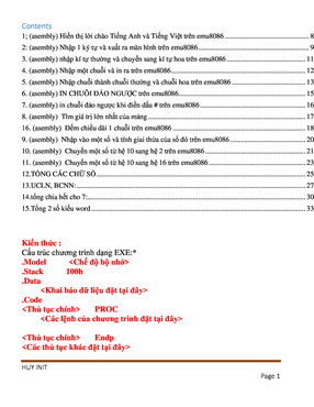
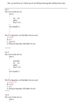
Information exchange mechanisms
The following figure outlines the information exchange mechanisms used in
IEC61850, with ‘real’ devices on the right-hand side being conceptualised as ‘virtual’
devices in the middle:
Figure 1-1: Information exchange mechanisms in IEC61850
1.4.3.
Logical nodes and logical devices
In IEC61850, application functions are decomposed into logical nodes, which are
then used to exchange information. An example of a logical node is a virtual
representation of a circuit breaker class with the standardised class name XCBR.
Several logical nodes together build a logical device such as a protection relay or bay
unit. Conceptually, a key difference between a logical node and a logical device is
that a logical node is not unique and as such can be used in more than one logical
device, whereas a logical device is a single, unique entity. One or more logical
devices can be utilised to cover the full functionality of a substation equipment bay.
Issue 10
CaSEnx (Callistonx Software Editor) User Manual
Page 18 of 342
2012 Remsdaq Ltd
USR00207
1.5.
Section 1: Introduction
Types of configuration files
CaSEnx operates with the following types of configuration files:
SCL file ‘SCL’ stands for ‘System Configuration Language’. This is the cover-all
term for all the types of configuration file.
SCD file ‘SCD’ stands for ‘Substation Configuration Description’. In overview, this is
the chief type of configuration file, geared to a specific real-world situation. It is the
only file type that you can download. In its fullest form, an SCD file contains (a) a
single line drawing of a substation plus logical nodes, (b) the specification of one or
more physical devices with their logical nodes, (c) details of the one or more
communications sub-networks hosting these physical devices, and (d) associations
between these various elements of the configuration, such as between the logical
nodes in the single line drawing and those on the physical device, so as to bind the
configuration into a coherent entity.
SSD file ‘SSD’ stands for ‘System Specification Description’. In overview, this is the
‘drawing’ element of the configuration. An SSD file contains a single line drawing of a
particular substation, together with its logical nodes. However, it has no references to
physical devices or logical devices. An SSD file falls short of an SCD file because it is
missing details of any physical devices.
ICD file ‘ICD’ stands for ‘IED Capability Description’ where an IED is a physical
device. In overview, this is the ‘device’ element of the configuration. It contains the
specification of a generic physical device, with its logical nodes. However, an ICD file
has no references to real-world physical devices. An ICD file falls short of an SCD file
because it is missing (a) a single line drawing and (b) details of real-world physical
devices.
CID files ‘CID’ stands for ‘Configured IED Description’ where an IED is a physical
device. This is an internally-generated file created automatically by CaSEnx during
downloads. It is a reduced form of SCD file that contains the configuration
information for a specific physical device.
Issue 10
CaSEnx (Callistonx Software Editor) User Manual
Page 19 of 342
2012 Remsdaq Ltd
USR00207
1.6.
Section 1: Introduction
Configuration strategy documented in this
manual
This manual describes how to create an SCD file.
1.7.
Physical devices, IEDs, and Callistonx and
Callistonxl units
In this manual, IEDs (intelligent electronic devices), Callistonx units and Callistonxl
units are all types of physical device. Wherever possible, we refer to Callistonx and
Callistonxl units collectively as physical devices, unless it is appropriate to distinguish
between the two types of unit. Finally, this manual was originally written for Callistonx
which is why so many of the examples have Callistonx units as their physical devices.
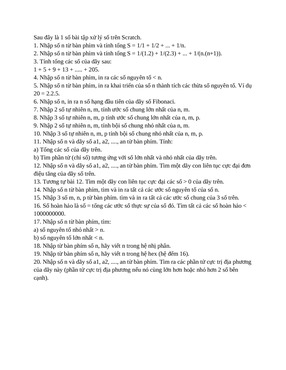
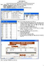
1.8.
Description of icons used in figures
Figure 1-2: Description of icons used in figures
Issue 10
CaSEnx (Callistonx Software Editor) User Manual
Page 20 of 342
2012 Remsdaq Ltd