Computer Graphics
About the Tutorial
To display a picture of any size on a computer screen is a difficult process.
Computer graphics are used to simplify this process. Various algorithms and
techniques are used to generate graphics in computers. This tutorial will help you
understand how all these are processed by the computer to give a rich visual
experience to the user.
Audience
This tutorial has been prepared for students who don’t know how graphics are
used in computers. It explains the basics of graphics and how they are
implemented in computers to generate various visuals.
Prerequisites
Before you start proceeding with this tutorial, we assume that you are already
aware of the basic concepts of C programming language and basic mathematics.
Copyright & Disclaimer
Copyright 2015 by Tutorials Point (I) Pvt. Ltd.
All the content and graphics published in this e-book are the property of Tutorials
Point (I) Pvt. Ltd. The user of this e-book is prohibited to reuse, retain, copy,
distribute or republish any contents or a part of contents of this e-book in any
manner without written consent of the publisher.
We strive to update the contents of our website and tutorials as timely and as
precisely as possible, however, the contents may contain inaccuracies or errors.
Tutorials Point (I) Pvt. Ltd. provides no guarantee regarding the accuracy,
timeliness or completeness of our website or its contents including this tutorial. If
you discover any errors on our website or in this tutorial, please notify us at
[email protected]
i
Computer Graphics
Table of Contents
About the Tutorial .................................................................................................................................. i
Audience ................................................................................................................................................ i
Prerequisites .......................................................................................................................................... i
Copyright & Disclaimer ........................................................................................................................... i
Table of Contents .................................................................................................................................. ii
1.
COMPUTER GRAPHICS – BASICS......................................................................................... 1
Cathode Ray Tube ................................................................................................................................. 1
Raster Scan ............................................................................................................................................ 2
Application of Computer Graphics ......................................................................................................... 3
2.
LINE GENERATION ALGORITHM ......................................................................................... 5
DDA Algorithm ...................................................................................................................................... 5
Bresenham’s Line Generation ................................................................................................................ 6
Mid-Point Algorithm .............................................................................................................................. 9
3.
CIRCLE GENERATION ALGORITHM ................................................................................... 11
Bresenham’s Algorithm ....................................................................................................................... 11
Mid Point Algorithm ............................................................................................................................ 13
4.
POLYGON FILLING ............................................................................................................ 16
Scan Line Algorithm ............................................................................................................................. 16
Flood Fill Algorithm ............................................................................................................................. 17
Boundary Fill Algorithm ....................................................................................................................... 18
4-Connected Polygon ........................................................................................................................... 18
8-Connected Polygon ........................................................................................................................... 19
Inside-outside Test .............................................................................................................................. 21
ii
Computer Graphics
5.
VIEWING AND CLIPPING................................................................................................... 24
Point Clipping ...................................................................................................................................... 24
Line Clipping ........................................................................................................................................ 24
Cohen-Sutherland Line Clippings ......................................................................................................... 25
Cyrus-Beck Line Clipping Algorithm ..................................................................................................... 27
Polygon Clipping (Sutherland Hodgman Algorithm) ............................................................................. 28
Text Clipping ........................................................................................................................................ 29
Bitmap Graphics .................................................................................................................................. 31
6.
2D TRANSFORMATION ..................................................................................................... 33
Homogenous Coordinates ................................................................................................................... 33
Translation .......................................................................................................................................... 33
Rotation .............................................................................................................................................. 34
Scaling ................................................................................................................................................. 36
Reflection ............................................................................................................................................ 37
Shear ................................................................................................................................................... 38
Composite Transformation .................................................................................................................. 39
7.
3D GRAPHICS ................................................................................................................... 41
Parallel Projection ............................................................................................................................... 41
Orthographic Projection ...................................................................................................................... 42
Oblique Projection............................................................................................................................... 43
Isometric Projections ........................................................................................................................... 43
Perspective Projection ......................................................................................................................... 44
Translation .......................................................................................................................................... 45
Rotation .............................................................................................................................................. 46
Scaling ................................................................................................................................................. 47
Shear ................................................................................................................................................... 48
iii
Computer Graphics
Transformation Matrices ..................................................................................................................... 49
8.
CURVES ............................................................................................................................ 51
Types of Curves ................................................................................................................................... 51
Bezier Curves ....................................................................................................................................... 52
Properties of Bezier Curves.................................................................................................................. 52
B-Spline Curves .................................................................................................................................... 53
Properties of B-spline Curve ................................................................................................................ 54
9.
SURFACES ........................................................................................................................ 55
Polygon Surfaces ................................................................................................................................. 55
Polygon Tables .................................................................................................................................... 55
Plane Equations ................................................................................................................................... 57
Polygon Meshes .................................................................................................................................. 57
10.
VISIBLE SURFACE DETECTION........................................................................................... 59
Depth Buffer (Z-Buffer) Method .......................................................................................................... 59
Scan-Line Method ................................................................................................................................ 61
Area-Subdivision Method .................................................................................................................... 61
Back-Face Detection ............................................................................................................................ 62
A-Buffer Method ................................................................................................................................. 64
Depth Sorting Method ......................................................................................................................... 65
Binary Space Partition (BSP) Trees ....................................................................................................... 66
11.
FRACTALS ......................................................................................................................... 68
What are Fractals? ............................................................................................................................... 68
Generation of Fractals ......................................................................................................................... 68
Geometric Fractals .............................................................................................................................. 69
12.
COMPUTER ANIMATION .................................................................................................. 71
iv
Computer Graphics
Animation Techniques ......................................................................................................................... 71
Key Framing ......................................................................................................................................... 72
Morphing............................................................................................................................................. 73
v
Computer Graphics
1. COMPUTER GRAPHICS – BASICS
Computer graphics is an art of drawing pictures on computer screens with the help of
programming. It involves computations, creation, and manipulation of data. In other
words, we can say that computer graphics is a rendering tool for the generation and
manipulation of images.
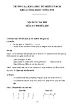
Cathode Ray Tube
The primary output device in a graphical system is the video monitor. The main
element of a video monitor is the Cathode Ray Tube (CRT), shown in the following
illustration.
The operation of CRT is very simple:
1. The electron gun emits a beam of electrons (cathode rays).
2. The electron beam passes through focusing and deflection systems that direct it
towards specified positions on the phosphor-coated screen.
3. When the beam hits the screen, the phosphor emits a small spot of light at each
position contacted by the electron beam.
4. It redraws the picture by directing the electron beam back over the same screen
points quickly.
Figure: Cathode Ray Tube
1
Computer Graphics
There are two ways (Random scan and Raster scan) by which we can display an object
on the screen.
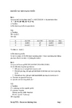
Raster Scan
In a raster scan system, the electron beam is swept across the screen, one row at a
time from top to bottom. As the electron beam moves across each row, the beam
intensity is turned on and off to create a pattern of illuminated spots.
Picture definition is stored in memory area called the Refresh Buffer or Frame
Buffer. This memory area holds the set of intensity values for all the screen points.
Stored intensity values are then retrieved from the refresh buffer and “painted” on the
screen one row (scan line) at a time as shown in the following illustration.
Each screen point is referred to as a pixel (picture element) or pel. At the end of
each scan line, the electron beam returns to the left side of the screen to begin
displaying the next scan line.
Figure: Raster Scan
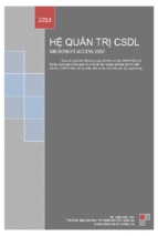
Random Scan (Vector Scan)
In this technique, the electron beam is directed only to the part of the screen where
the picture is to be drawn rather than scanning from left to right and top to bottom as
in raster scan. It is also called vector display, stroke-writing display, or
calligraphic display.
Picture definition is stored as a set of line-drawing commands in an area of memory
referred to as the refresh display file. To display a specified picture, the system
2
Computer Graphics
cycles through the set of commands in the display file, drawing each component line
in turn. After all the line-drawing commands are processed, the system cycles back to
the first line command in the list.
Random-scan displays are designed to draw all the component lines of a picture 30 to
60 times each second.
Figure: Random Scan
Application of Computer Graphics
Computer Graphics has numerous applications, some of which are listed below:
Computer graphics user interfaces (GUIs) – A graphic, mouse-oriented
paradigm which allows the user to interact with a computer.
Business presentation graphics - "A picture is worth a thousand words".
Cartography - Drawing maps.
Weather Maps – Real-time mapping, symbolic representations.
Satellite Imaging - Geodesic images.
Photo Enhancement - Sharpening blurred photos.
Medical imaging - MRIs, CAT scans, etc. - Non-invasive internal examination.
3
Computer Graphics
Engineering drawings - mechanical, electrical, civil, etc. - Replacing the
blueprints of the past.
Typography - The use of character images in publishing - replacing the hard
type of the past.
Architecture - Construction plans, exterior sketches - replacing the blueprints
and hand drawings of the past.
Art - Computers provide a new medium for artists.
Training - Flight simulators, computer aided instruction, etc.
Entertainment - Movies and games.
Simulation and modeling - Replacing physical modeling and enactments
4
Computer Graphics
2. LINE GENERATION ALGORITHM
A line connects two points. It is a basic element in graphics. To draw a line, you need
two points between which you can draw a line. In the following three algorithms, we
refer the one point of line as X0, Y0 and the second point of line as X1, Y1.
DDA Algorithm
Digital Differential Analyzer (DDA) algorithm is the simple line generation algorithm
which is explained step by step here.
Step 1: Get the input of two end points (X0, Y0) and (X1, Y1).
Step 2: Calculate the difference between two end points.
dx = X1 - X0
dy = Y1 - Y0
Step 3: Based on the calculated difference in step-2, you need to identify the number
of steps to put pixel. If dx > dy, then you need more steps in x coordinate; otherwise
in y coordinate.
if (dx > dy)
Steps = absolute(dx);
else
Steps = absolute(dy);
Step 4: Calculate the increment in x coordinate and y coordinate.
Xincrement = dx / (float) steps;
Yincrement = dy / (float) steps;
5
Computer Graphics
Step 5: Put the pixel by successfully incrementing x and y coordinates accordingly and
complete the drawing of the line.
for(int v=0; v < Steps; v++)
{
x = x + Xincrement;
y = y + Yincrement;
putpixel(x,y);
}
Bresenham’s Line Generation
The Bresenham algorithm is another incremental scan conversion algorithm. The big
advantage of this algorithm is that, it uses only integer calculations. Moving across the
x axis in unit intervals and at each step choose between two different y coordinates.
For example, as shown in the following illustration, from position (2, 3) you need to
choose between (3, 3) and (3, 4). You would like the point that is closer to the original
line.
At sample position xk+1, the vertical separations from the mathematical line are
labelled as
dupper and dlower.
6
Computer Graphics
From the above illustration, the y coordinate on the mathematical line at xk+1 is:
𝑌 = 𝑚(𝑋 𝑘 + 1) + 𝑏
So,
dupper and dlower are given as follows:
𝑑 𝑙𝑜𝑤𝑒𝑟 = 𝑦 − 𝑦 𝑘
= 𝑚(𝑋 𝑘 + 1) + 𝑏 − 𝑌 𝑘
and
𝑑 𝑢𝑝𝑝𝑒𝑟 = (𝑦 𝑘 + 1) − 𝑦
= 𝑌 𝑘 + 1 − 𝑚(𝑋 𝑘 + 1) − 𝑏
You can use these to make a simple decision about which pixel is closer to the
mathematical line. This simple decision is based on the difference between the two
pixel positions.
𝑑 𝑙𝑜𝑤𝑒𝑟 − 𝑑 𝑢𝑝𝑝𝑒𝑟 = 2𝑚(𝑥 𝑘 + 1) − 2𝑦 𝑘 + 2𝑏 − 1
Let us substitute m with dy/dx where dx and dy are the differences between the endpoints.
𝑑𝑥(𝑑 𝑙𝑜𝑤𝑒𝑟 − 𝑑 𝑢𝑝𝑝𝑒𝑟 ) = 𝑑𝑥(2
𝑑𝑦
(𝑥 𝑘
𝑑𝑥
+ 1) − 2𝑦 𝑘 + 2𝑏 − 1)
= 2𝑑𝑦 ∙ 𝑥 𝑘 − 2𝑑𝑥 ∙ 𝑦 𝑘 + 2𝑑𝑦 + 𝑑𝑥(2𝑏 − 1)
= 2𝑑𝑦 ∙ 𝑥 𝑘 − 2𝑑𝑥 ∙ 𝑦 𝑘 + 𝐶
So, a decision parameter
pk for the kth step along a line is given by:
𝑝 𝑘 = 𝑑𝑥(𝑑 𝑙𝑜𝑤𝑒𝑟 − 𝑑 𝑢𝑝𝑝𝑒𝑟 )
= 2𝑑𝑦 ∙ 𝑥 𝑘 − 2𝑑𝑥 ∙ 𝑦 𝑘 + 𝐶
The sign of the decision parameter
pk is the same as that of dlower – dupper.
7
Computer Graphics
If
pk is negative, then choose the lower pixel, otherwise choose the upper pixel.
Remember, the coordinate changes occur along the x axis in unit steps, so you can do
everything with integer calculations. At step k+1, the decision parameter is given as:
𝑝 𝑘+1 = 2𝑑𝑦 ∙ 𝑥 𝑘+1 − 2𝑑𝑥 ∙ 𝑦 𝑘+1 + 𝐶
Subtracting
pk from this we get:
𝑝 𝑘+1 − 𝑝 𝑘 = 2𝑑𝑦(𝑥 𝑘+1 − 𝑥 𝑘 ) − 2𝑑𝑥(𝑦 𝑘+1 − 𝑦 𝑘 )
But,
xk+1 is the same as xk+1. So:
𝑝 𝑘+1 = 𝑝 𝑘 + 2𝑑𝑦 − 2𝑑𝑥(𝑦 𝑘+1 − 𝑦 𝑘 )
Where,
yk+1 – yk is either 0 or 1 depending on the sign of pk.
The first decision parameter p0 is evaluated at (x0, y0) is given as:
𝑝0 = 2𝑑𝑦 − 𝑑𝑥
Now, keeping in mind all the above points and calculations, here is the Bresenham
algorithm for slope m < 1:
Step 1: Input the two end-points of line, storing the left end-point in (x0, y0).
Step 2: Plot the point (x0, y0).
Step 3: Calculate the constants dx, dy, 2dy, and (2dy – 2dx) and get the first value
for the decision parameter as:
𝑝0 = 2𝑑𝑦 − 𝑑𝑥
Step 4: At each
xk along the line, starting at k = 0, perform the following test:
If pk < 0, the next point to plot is (xk+1, yk) and
𝑝 𝑘+1 = 𝑝 𝑘 + 2𝑑𝑦Otherwise,
𝑝 𝑘+1 = 𝑝 𝑘 + 2𝑑𝑦 − 2𝑑𝑥
Step 5: Repeat step 4 (dx – 1) times.
For m > 1, find out whether you need to increment x while incrementing y each time.
After solving, the equation for decision parameter
and y in the equation gets interchanged.
pk will be
very similar, just the x
8
Computer Graphics
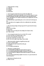
Mid-Point Algorithm
Mid-point algorithm is due to Bresenham which was modified by Pitteway and Van
Aken. Assume that you have already put the point P at (x, y) coordinate and the slope
of the line is 0 ≤ k ≤ 1 as shown in the following illustration.
Now you need to decide whether to put the next point at E or N. This can be chosen
by identifying the intersection point Q closest to the point N or E. If the intersection
point Q is closest to the point N then N is considered as the next point; otherwise E.
Figure: Mid-point Algorithm
To determine that, first calculate the mid-point M(x+1, y + ½). If the intersection point
Q of the line with the vertical line connecting E and N is below M, then take E as the
next point; otherwise take N as the next point.
In order to check this, we need to consider the implicit equation:
F(x,y) = mx + b - y
For positive m at any given X,
If y is on the line, then F(x, y) = 0
If y is above the line, then F(x, y) < 0
If y is below the line, then F(x, y) > 0
9
Computer Graphics
10
Computer Graphics
3. CIRCLE GENERATION ALGORITHM
Drawing a circle on the screen is a little complex than drawing a line. There are two
popular algorithms for generating a circle: Bresenham’s Algorithm and Midpoint
Circle Algorithm. These algorithms are based on the idea of determining the
subsequent points required to draw the circle. Let us discuss the algorithms in detail:
The equation of circle is X2 + Y2 = r2, where r is radius.
(-b,a)
(b,a)
(-a,b)
(a,b)
(-a,-b)
(a,-b)
(-b,-a)
(b,-a)
Bresenham’s Algorithm
We cannot display a continuous arc on the raster display. Instead, we have to choose
the nearest pixel position to complete the arc.
From the following illustration, you can see that we have put the pixel at (X, Y) location
and now need to decide where to put the next pixel: at N (X+1, Y) or at S (X+1, Y-1).
11
Computer Graphics
This can be decided by the decision parameter d.
If d <= 0, then N(X+1, Y) is to be chosen as next pixel.
If d > 0, then S(X+1, Y-1) is to be chosen as the next pixel.
Algorithm
Step 1: Get the coordinates of the center of the circle and radius, and store them in
x, y, and R respectively. Set P=0 and Q=R.
Step 2: Set decision parameter D = 3 – 2R.
Step 3: Repeat through step-8 while X < Y.
Step 4: Call Draw Circle (X, Y, P, Q).
Step 5: Increment the value of P.
Step 6: If D < 0 then D = D + 4x + 6.
Step 7: Else Set Y = Y + 1, D = D + 4(X-Y) + 10.
Step 8: Call Draw Circle (X, Y, P, Q).
Draw Circle Method(X, Y, P, Q).
Call Putpixel (X + P, Y + Q).
Call Putpixel (X - P, Y + Q).
Call Putpixel (X + P, Y - Q).
Call Putpixel (X - P, Y - Q).
Call Putpixel (X + Q, Y + X).
12
Computer Graphics
Call Putpixel (X - Q, Y + X).
Call Putpixel (X + Q, Y - X).
Call Putpixel (X - Q, Y - X).
Mid Point Algorithm
Step 1: Input radius r and circle center (xc, yc) and obtain the first point on the
circumference of the circle centered on the origin as
(x0, y0) = (0, r)
Step 2: Calculate the initial value of decision parameter as
P0 = 5/4 – r (See the following description for simplification of this equation.)
f(x, y) = x2 + y2 - r2 = 0
f(xi - 1/2 + e, yi + 1)
= (xi - 1/2 + e)2 + (yi + 1)2 - r2
= (xi- 1/2)2 + (yi + 1)2 - r2 + 2(xi - 1/2)e + e2
= f(xi - 1/2, yi + 1) + 2(xi - 1/2)e + e2 = 0
13
Computer Graphics
Let di = f(xi - 1/2, yi + 1) =
-2(xi - 1/2)e - e2
Thus,
If e < 0 then di > 0 so choose point S = (xi - 1, yi + 1).
di+1
= f(xi – 1 - 1/2, yi + 1 + 1) = ((xi - 1/2) - 1)2 + ((yi + 1) + 1)2 - r2
= di - 2(xi - 1) + 2(yi + 1) + 1
= di + 2(yi+1 - xi+1) + 1
If e >= 0 then di <= 0 so choose point T = (xi, yi + 1)
di+1
= f(xi - 1/2, yi + 1 + 1)
= di + 2yi+1 + 1
The initial value of di is
d0
=
f(r - 1/2,
=
5/4 - r
0 + 1) = (r - 1/2)2 + 12 - r2
{1 - r can be used if r is an integer}
When point S = (xi - 1, yi + 1) is chosen, then
14