THAI NGUYEN UNIVERSITY OF TECHNOLOGY
Faculty of International Training
CAN CRUSHER
Design Project Report
by:
Phan Thi Hong Mai
K49APM – K145905228006
Instructor:
Associate Professor Dr. Nguyen Van Du
Submitted to
The Faculty of International Training
In the fulfillment of the project for the subject Process Design
and Methods
FEBRUARY 2017
CAN CRUSHER
Designed by:
Phan Thi Hong Mai
Instructor:
Associate Professor Dr. Nguyen Van Du
Submitted to
The Faculty of International Training
In the fulfillment of the project for the subject Process Design and Methods
Faculty of International Training
Thai Nguyen University of
Technology
1
February, 2017
ACKNOWLEDGEMENT
We would like to express our high appreciation to those who have been helping
and supporting us in the development and accomplishment of this project. Special
thanks to our supervisor Associate Professor Dr. Nguyen Van Du for his support and
encouragement throughout the project.
We also would like to thank our friends for their encouragement and assistance
along the development of the project.
2
ABSTRACT
.
Used aluminum cans are one of the causes of environment pollution. Therefore we
must find a way to reuse or recycle them in order to protect our environment. Can crusher
is a device that helps to crush used cans for storage or recycling. In this project, we focus
on generating several ideas for designing an electrical can crusher base on our customer’s
requirement. One best solution will be chosen and introduced to configuration design,
detail design. After that we start to manufacture the product and test its capacity. Finally,
we are able to manufacture a complete can crusher that has all the requirements
mentioned above.
3
Table of Contents
Page(s)
ACKNOWLEDGEMENT...........................................................................................................................2
ABSTRACT................................................................................................................................................3
CHAPTER 1)
INTRODUCTION.......................................................................................................6
1.4.1
Foot Operated Can Crusher.........................................................................................................8
1.4.2
Hand operated Can Crusher.........................................................................................................9
1.4.3
Simple Can Crusher Using Motor................................................................................................9
1.5 Product Orientation..............................................................................................................................10
CHAPTER 2)
PROBLEM STATEMENT........................................................................................11
2.1 Kind of Power Transmission...............................................................................................................11
2.3 Identification of Engineering Specification.........................................................................................11
2..4 Conclusion..........................................................................................................................................12
CHAPTER 3)
CONCEPT DESIGN..................................................................................................13
3.1 Introduction.........................................................................................................................................13
3.2 Building Function Structure Diagram..................................................................................................13
3.3 Generating Alternative Solutions.........................................................................................................14
3.4 Mixing the Sub-functions....................................................................................................................18
3.5 Decision Making.................................................................................................................................19
3.6 Conclusion...........................................................................................................................................20
CHAPTER 4) CONFIGURATION DESIGN.......................................................................................20
4.1 Introduction.........................................................................................................................................20
4.2 Mechanical parts..................................................................................................................................20
4.3 Power transmission..............................................................................................................................22
4.4 Conclusion...........................................................................................................................................22
CHAPTER 5) CHAPTER 5 DETAIL DESIGN....................................................................................22
5.1 Introduction.........................................................................................................................................22
5.2 Stress Analysis.....................................................................................................................................22
5.3 Determination of Form and Dimension...............................................................................................22
4
5.4 Price.....................................................................................................................................................25
5.5 Conclusion...........................................................................................................................................25
CHAPTER 6) MANUFACTURING.....................................................................................................26
CHAPTER 7) TESTING.......................................................................................................................26
CHAPTER 8) CONCLUSION..............................................................................................................26
CHAPTER 9) References......................................................................................................................26
5
CHAPTER 1) INTRODUCTION
The most frequent use of aluminum is in beverage cans. Since we use aluminum so
frequently it is important to get as many uses out of it as we can. Recycling aluminum not
only helps to keep the landfills clear but it also saves energy.
1.1 Aluminum cans
An aluminum can, sometimes referred to as a "tin can", is a container
for packaging made primarily of aluminum. It is commonly used for foods and beverages
but also for products such as oil, chemicals, and other liquids. Global production is 180
billion annually and composes of the biggest single use of aluminum globally.
1.2 Aluminum recycling
Aluminum recycling is the process by which scarp aluminum can be reused in
products after its initial production. The recycling of aluminum generally produces
significant cost savings over the production of new aluminum, even when the cost of
collection, separation and recycling are taken into account. Over the long term, even
larger national savings are made when the reduction in the capital costs associated
with landfills, mines, and international shipping of raw aluminum are considered.
1.2.1 Energy savings
Recycling wasted aluminum requires only 5% of the energy used to make new
aluminum. For this reason, approximately 31% of all aluminum produced in the United
States comes from recycled scrap. Used beverage containers are the largest component of
processed aluminum scrap, and most of it is manufactured back into aluminum cans.
Aluminum can be recycled forever - without losing any of its qualities.
6
1.2.2. Environment protection
Along with the energy savings, recycling aluminum saves around 95% of the
greenhouse gas emissions compared to the primary production process. Recycling 1 ton
of aluminum saves 9 tons of CO2 emissions.
1.3 Can Crushers
Recycling process requires a large space to store used cans. We need a device that
can reduce the volume of scrap cans. There are several ways of compressing a can. We
sometimes use our feet to crush an aluminum can by jumping or stepping on it. Using a
device to crush the can is a better solution, by which we can save time and energy. We
can save more space in the recycle bin and store more cans with this can crusher!
Its fundamental working principle consists of three steps:
1. Inserting a used can.
2. Crushing it.
3. Taking the crushed can out of the crusher.
1.4 Literature review
In this session, we will study some common types of can crushers. Can crusher
can be of many types according to how they works; it can be mechanical,
hydraulic, pneumatic and magnetic. Hydraulic can crusher work without the
use of water and certainly are devoid of any sound or calibrations. But
mostly the ones we commonly find in the market are electronic or manual
operation.
1.4.1 Foot Operated Can Crusher
7
Figure 1.1: Foot Operated Can Crusher
Advantages
Disadvantages
Low efficiency
Simple to design
Do not have space to store crushed cans
Cheap to produce
Can crush only one can at a time
Environmentally friendly
Easy to operate
1.4.2 Hand operated Can Crusher
8
Figure 1.2 Hand Operated Can Crusher
Advantages
Easy to operate
Disadvantages
Do not have space to store crushed cans
Simple to design
Can crush only one can at a time
Cheap to produce
Suitable for domestic uses
Environmentally friendly
1.4.3 Simple Can Crusher Using Motor
Figure 1.3 Simple can crusher using motor
Advantages
High efficiency
Disadvantages
More expensive to manufacture
Easy to operate
compare to manual can crushers
Consume electricity which is not
Have space to store can
considered to be environmentally
Save labor force
friendly
1.5 Product Orientation
9
We will develop a can crusher that possesses the following characteristics:
1. Simple
2. Easy to operate and maintain
3. Low cost
4. Lessen the volume of the can about 60%
5. Can crush 20 cans/ min
CHAPTER 2) PROBLEM STATEMENT
2.1 Criteria
1.
2.
3.
4.
5.
Kind of Power Transmission: Electricity
Dimension: As small as possible
Cost: Less than 1 million VND
Reduce the number of tasks
Simple part structure
2.2 Identification of Engineering Specification
2.2.1 Customer’s requirements
Surveys, questionnaires and some other necessary measurements had been done to gather
the customer requirements. Our customer has some expectations of the product as follow:
1.
2.
3.
4.
5.
Easy to use
Low cost
Safe to use
Lightweight
Durable
2.2.2 Engineering specification
Based on our customer’s requirements, we develop a set of engineering specifications
that we would like our product to have. These specifications are the restatement of the
design problem in term of parameters that can be measured and have target values. Some
of the engineering specifications created are:
1.
2.
3.
4.
Step to operate
Product weight
Product cost
Material usage
10
2.3. HOQ of a can crusher
The HOQ was made after gathering all the information as below:
3
9
1
9
Steps to
operate
Product
weight
Product
cost
Steps
9
3
N
VND
Material
usage
Customer
Easy to use
Low cost
20
15
Safe to use
Light weight
Durable
Less noise
15
13
30
7
Importance
Company A
Company B
Target (Delighted)
Threshold (Disgusted)
**
*
**
**
*
1
1
9
9
38
85
87
90
85
1= bad
3 = good
* Company A
** Company B
1
2
3
5
15
20
10
15
70
75
60
80
*
**
*
** *
*
**
16
30
26
25
35
Figure 2.1 House of Quality
2.4 Conclusion
The aim of this chapter is to find out what the customer needs and what we, engineers,
need to do in order to satisfy those needs of our customers. The House of Quality (HOQ)
of the can crusher was made to determine the engineering specifications. From the HOQ
above, we can conclude that the highest rating of customer requirement is durability. And
also the highest importance of the engineering specification is
CHAPTER 3) CONCEPT DESIGN
3.1 Introduction
This chapter aims to show some ideas of designing a can crusher by focusing on
building the function structure diagram and after proposing several feasible solutions, one
best design shall be chosen to be further discussed in the next chapter, Chapter 4
Configuration Design. A Function Structure Diagrams (FSD) is a graphical
11
representation of the functions a product performs on its inputs and outputs. In a FSD, the
overall function is broken down into elemental or atomic sub-functions. Each subfunction cannot be broken down further and is solution neutral. The sub-functions are
connected by “flows” on which they operate. Flows are materials, energy or information
that is used by or affects the product. FSDs are used for many tasks in the design process.
3.2 Building Function Structure Diagram
The Function Structure Diagram of a can crusher is shown in the Figure 3.1. There
are six sub-functions in the diagram including Accept, Store, Align, Hold, Crush, and
Reject. Each of them plays a vital role in the process of crushing cans.
Figure 1 Function structure diagram of a can crusher.
3.3 Generating Alternative
Electricity
Used
can
Accept
Accept
Solutions
Align
Deliver
Hold
Trip
signal
Sense trip
Heat
Convert energy
Store
Store
Noise
Crush
Trigger tool
3.3.1 Sub – function “Accept/Store the can”
Three best options will be investigated.
Option 1: Place in apparatus by hand.
Pros:
- Simple
- Easy
Cons:
12
Eject
Compress can
- Low efficiency if one
Option 2:
Pros:
- Combine a store which can have a capacity of 6 cans
- High efficiency
Cons:
- Cost of material
- Need a solution for deliver and align the cans.
Option 3:
Pros:
- Combine a store which can have a capacity of 5 cans
- High efficiency
Cons:
- Complex
- Limit the number of parts
- Difficult to maintain and manufacture
3.3.2 Sub – function “Align the can”
Option 1
Option 2
Option 3
3.3.2 Sub – function “Hold the can”
Option 1
13
Option 2
3.3.2 Sub – function “Crush the can”
Option 1
Option 2
3.3.2 Sub – function “Eject the can”
Option 1
Option 2
3.4 Mixing the Sub-functions
Option 1
Option 2
14
Option 3
A. Accept
H. Hold
C. Crush can
E. Eject
Table 1. Feasible solutions for a can crusher
3.4.1 Concept 1
Can
Pros(+)
Cons(-)
High efficiency
Easy to eject the can
Cans might get stuck when accepting the cans
Complex to manufacture the parts
Use electricity
15
3.4.2 Concept 2
Pros(+)
Cons(-)
No need a lot of space
Aluminum can bin does not slide in and out
Materials used are expensive because it
Easy to use
should be light.
3.4.3 Concept 3
Can
Pros(+)
Cons(-)
Easy to put the can in the right place for
Use of electricity
crushing
Easy to eject the can
Easy to crush the can
Cause vibration and noise
3.5 Decision Making
16
Above is three best concept that we have evaluated. Comparison between advantages and
disadvantages have also been done. For further analysis to choose the best concept, a
Pugh matrix is done below
Criteria
Importance
weight (%)
Durable
25
Light weight
10
High efficiency 15
High reliability
15
Easy to use
10
Easy
to 15
manufacture
Low cost
10
100
Rating
Unsatisfactory
Just tolerable
Adequate
Good
Very good
Concept 1
Rating
Weighte
d Rating
3
0.75
3
0.3
3
0.45
3
0.45
3
0.3
3
0.45
Concept 2
Ratin Weighted
g
Rating
2
0.5
4
0.4
1
0.15
3
0.45
2
0.2
2
0.3
Concept 3
Ratin Weighted
g
Rating
3
0.75
3
0.3
4
0.6
4
0.6
4
0.4
4
0.6
3
NA
2
NA
2
NA
0.3
3
0.2
2.2
0.2
3.45
Value
0
1
2
3
4
3.6 Conclusion
In this chapter, we proposed several sub-functions for the FSD, generated various ideas
and comparing advantages and disadvantages of feasible solutions. Based on the results
of Pugh matrix, we can conclude that Concept 3 is the best possible design for our can
crusher. Therefore, concept 3 will be introduced to be configured and give proper
dimension in the latter chapters.
CHAPTER 4) CONFIGURATION DESIGN
4.1 Introduction
In this chapter, we determine one or more feasible concepts for the parts that go
into our product. The concepts are merely abstract embodiments of physical
principles, working geometries, and materials.
17
4.2 Mechanical parts
The main mechanical parts of the can crusher are listed as below:
Basement( including the piston chamber)
Motor
Slider mechanism
Crank (in disk shape)
Rod
Slider
We take the slider-crank mechanism as the first step of designing. After that, the
other component will be determined by the result of this process.
The motor : 10 rpm
Offset distance : 90 mm
For crushing the can with 60 % size reduced. The link 3 need to move a distance of
110 mm. By the calculations, we get:
Link 1 : The disk, diameter Ø = 55 mm
Link 2 : Crank : L = 280 mm
Link 3: Slider : hollow cylindrical part with Ø = 78 mm.
18
We can determine the mechanical parts and theirs requirement as follow:
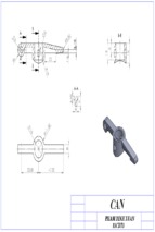
1. Connecting rod
-
Connections at both ends
-
Able to undergo the compress force during compression process.
2. Slider (piston)
-
The other end has a plate to compress the cans
-
Long cylindrical shape (the plate always perpendicular to the cans, slider
always contact with the slide-way, better balance, …)
3. Slide-way (piston chamber)
-
Mounted firmly to the basement
-
One dead end to compress the cans
-
Open space to eject the compressed can out
-
Open space to place the empty can in.
-
Cylindrical shape to stable the slider and cans.
4.3 Power transmission
In this part of the project, how the transmission of power from the motor up to the crusher
will be discussed.
4.3.1. Power source
We will be using a DC motor 24V, 10rpm available on the market
4.3.2 Mechanical Drive
4.4 Conclusion
CHAPTER 5) CHAPTER 5 DETAIL DESIGN
5.1 Introduction
Following FEED is the Detailed Design (Detailed Engineering) phase, which may consist
of procurement of materials as well. This phase further elaborates each aspect of the
19
- Xem thêm -

