UPS ngoài acquy nội, UPS còn có thể được đấu nối thêm bình ngoài để tăng thời gian lưu
điện. Việc đấu nối khá đơn giản, các bạn có thể tự làm 1 cái để sử dụng trong nhà rất hiệu
quả.
Các bạn cùng tham khảo cách đấu nối thêm acquy mở rộng và cấu hình khi lắp acquy
ngoài cho UPS APC 3KVA như bên dưới:
: – Thời gian sử dụng điện bình của UPS được tính toán và lưu trong EEPROM, vì vậy khi
thay bình mới (17Ah) hoặc cứ 1 năm thì cần phải calibrate lại để UPS tính toán đúng thời
gian sử dụng.
– Nếu ta thay bình có dung lượng lớn hơn bình zin (17Ah) thì phải làm động tác giả là add
thêm battery cho UPS. UPS có một ngõ DC in ở đằng sau để cho phép gắn thêm các tổ
hợp bình để tăng thời gian sử dụng. Vì vậy nếu tui sử dụng bình 60Ah thì sẽ lấy 60/17 = 3.5
(chọn 2 là số tổ hợp bình add thêm và).
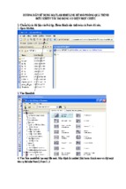
– Nối cable vào cổng COM của PC và UPS rồi chạy chương trình Hyper Terminal - Gõ đại
một cái tên vào rồi nhấn OK - Chọn COM1
- Chọn các thông số như sau Trong màn hình hyperterminal bấm chữ Y hoa. Nếu UPS trả
về SM thì kết nối thành công. Bấm dấu > UPS sẽ hiện ra số tổ hợp bình (nếu chưa add vào
sẽ là 000, của mình đã add nên là 002). Bấm dấu + để tăng số tổ hợp bình, dấu – để giảm.
Xong bấm > để kiểm tra lại.
– Thoát khỏi chương trình HyperTerminal – Xong chạy chương trình APC-Fix download
từ http://depositfiles.com/files/yisdoooxl để xem thời gian sử dụng bình của UPS nhé
Nếu các bác nghiên cứu protocol của APC
(http://www.networkupstools.org/protocols/apcsmart.html) thì sẽ chỉnh được một số các
thông số như: tắt tiếng beep của UPS khi mất điện nguồn, chỉnh điện áp ngõ ra 220V or
240V.
Còn nếu thấy dùng protocol phức tạp thì có thể download Apcupsd tại link
này http://www.apcupsd.com/ để chọc ngoáy UPS cho dễ
1
2
APC’s smart protocol
Table of Contents
JavaScript must be enabled in your browser to display the table of contents.
Description
Here’s the informaton on the elusive APC smart signalling protocol used by their higher end units (Back-UPS
Pro, Smart-UPS, Matrix-UPS, etc). What you see here has been collected from a variety of sources. Some
people analyzed the chater between PowerChute and their hardware. Others sent various characters to the
UPS and fgured out what the results meant.
RS-232 diferences
Normal 9 pin serial connectons have TxD on 3 and RxD on 2. APC’s smart serial ports put TxD on pin 1 and
RxD on pin 2. This means you go nowhere if you use a normal straight through serial cable. In fact, you might
even power down the load if you plug one of those cables in. This is due to the odd routng of pins - DTR and
RTS from the PC usually wind up driving the on/of line. So, when you open the port, they go high and *poof*
your computer dies.
Originally this evil hack was used to connect the UPS to the PC when this page was frst being built. As you
can see, I cheated and neglected the ground (only 2 wires!) and it stll worked. This method can be used for
playing around, but for professional systems this is obviously not a viable opton.
That hack didn’t work out so well (damned cats), so it was retred uite awhile back. The most practcal
soluton was to go out and BUY the DOS/Win version of Powerchute just for the black (smart) cable. I
3
recommend doing the same thing if you actually care about this thing working properly. Of course, if you
have one of the newer packages that came with PowerChute, you already have the cable you need.
Cable hacking
Figure 1. Redrawn 940-0024C clone diagram (D. Stimitss
Figure 2. Mac 940-0024C clone diagram (Miguel Howards
Figure 3. Original 940-0024C diagram (Steve Drapers
If you are handy with cable tools, check out these diagrams. They show how to clone the black "smart" cable
that’s normally provided with APC models sold afer 1996. The loopback pins (back to the PC) are used to
keep PowerChute happy by allowing cable detecton. If you use the NUT apcsmart or newapc drivers, those
pins don’t mater.
The Smart Protocol
Despite the lack of ofcial informaton from APC, this table has been constructed. It’s standard RS-232 serial
communicatons at 2400 bps/8N1. Don’t rush the UPS while transmitng or it may stop talking to you. This
4
isn’t a problem with the normal single character ueries, but it really does mater for mult-char things like
"@000". Sprinkle a few calls to usleep() in your code and everything will work a lot beter.
Character Meaning
Typical results
^A
Model string
SMART-UPS 700 Spoty support for this uery on older models
^N
Turn on UPS
n/a
Send twice with > 1.5s delay between chars
Only on 3rd gen SmartUPS and Black Back-UPS Pros
^Z
Capability string
(long string)
See "Capabilites" secton for more info
A
Front panel test
Light show +
"OK"
Also sounds the beeper for 2 seconds
B
Batery voltage
27.87
This obviously varies a lot based on the current charge.
Compare this to the nominal batery voltage
C
Internal temperature
036.0
Units are degrees C
!, then $
Runs untl batery is below 25% (35% for Matrix)
This updates the j values - only works at 100% batery
charge
Can be aborted with a second "D"
D
Runtme calibraton
Other info
E
Automatc selfest
intervals
336
Writable variable
Values:
336 (14 days)
168 (7 days)
ON (at power on) (note extra space)
OFF (never)
F
Line fre uency, Hz
60.00
If this varies much, have a word with your local
electrician
G
Cause of transfer
O
Writable variable
Values:
R (unacceptable utlity voltage rate of change)
H (high utlity voltage)
L (low utlity voltage)
T (line voltage notch or spike)
O (no transfers yet since turnon)
S (transfer due to U command or actvaton of
UPS test)
I
Measure-UPS: Alarm
enable
FF
(not yet decoded)(bitmapped table, coming soon)
J
Measure-UPS: Alarm
status
0F,00
(not yet decoded)(bitmapped table, coming soon)
K
Shutdown with grace
period
OK
Send twice with > 1.5s delay between chars
Older units may send "*" instead of "OK"
Also see grace period
L
Input line voltage
118.3
Does not necessarily read 000.0 on line failure
5
Character Meaning
Typical results
Other info
M
Maximum line voltage 118.9
This is the max voltage since the last tme this uery
was run
N
Minimum line voltage
118.9
Like the one above, this one also resets itself on every
uery
O
Output voltage
118.3
Also see on batery output voltage
P
Power load %
023.5
Relatve to the capacity of the UPS
Q
Status fags
08
See status fags secton for more info
BYE
Only on 3rd gen Smart-UPS, Smart-UPS v/s, Back-UPS
Pro
UPS must receive command to enter smart mode
contnue communicatons afer sending this
OK
Command executes afer grace period
UPS goes online when power returns
Only works when on batery
R
Turn dumb
S
Sof shutdown
U
Simulate power failure !, then $
See async notfer secton for info on ! and $
V
Firmware revision
GWD
Can be used to determine abilites of hardware
OK
Tests batery, like pushing the test buton on the front
panel
Also see test results entry
W
Self test
Values:
X
Self-test results
OK
Y
Enter smart mode
Z
Shutdown
immediately
OK → good batery
BT → failed due to insufcient capacity
NG → failed due to overload
NO → no results available (no test performed in
last 5 minutes)
SM
This must be sent before anything else on this page will
work.
Also see turn dumb command to exit smart mode
n/a
Send twice with > 1.5s delay between chars
UPS switches the load of immediately (no grace
period)
Returns three main sectons:
Protocol version
Alert messages (aka async notfers)
Valid commands
Sectons are separated with a period
a
Protocol info
(long string)
b
Firmware revision
50.9.D
Decoding above info:
50 SKU (variable length)
9
frmware revision
6
Character Meaning
Typical results
Other info
D
c
UPS local id
e
Return threshold
g
Nominal batery
voltage
f
Batery level
h
Measure-UPS:
Ambient humidity
country code (used in capability decoding)
UPS_IDEN
Writable variable
Up to 8 leter identfer for keeping track of your
hardware
00
Writable variable
Minimum batery charge % to return from shutdown
afer power returns
Values:
00 = 0% (UPS switches on immediately)
01 = 15%
02 = 25%
03 = 90%
This prevents excessive cycling during multple power
failures
024
The batery voltage that’s expected to be present in the
UPS normally
Compare to the actual voltage reading
099.0
Percentage
It’s much easier to use this rather than doing math on
the current batery voltage and the nominal batery
voltage
042.4
Percentage
Only works on models with the Measure-UPS SmartSlot
card
i
Measure-UPS: Dry
contacts
00
Bitmapped hex variable
Component values:
10 = contact 1
20 = contact 2
40 = contact 3
80 = contact 4
j
Estmated runtme
0327:
Minutes
Must be calibrated to be efectve
Writable variable
Values:
0 = 5 second delay afer power failure
T = 30 second delay
L = alarm at low batery only
N = alarm disabled
Does not afect low batery warning
k
Alarm delay
0
l
Low transfer voltage
103
Writable variable
See capabilites to get values for a UPS
UPS goes on batery afer voltage drops below this
7
Character Meaning
Typical results
Other info
point
Format may vary by country (MM/DD/YY vs
DD/MM/YY)
m
Manufacturing date
11/29/96
n
Serial number
WS9643050926 Uni ue for each UPS
o
On-batery voltage
115
p
q
r
s
May be a writable variable on 220/230/240 VAC units
Shutdown grace delay 020
Writable variable - seconds
See capabilites to read values
Sets the delay before sof shutdown completes
Low batery warning
02
Writable variable - minutes
See capabilites to read values
The UPS will report a low batery this many minutes
before it runs out of power
000
Writable variable - seconds
See capabilites to read values
The UPS will wait this many seconds afer reaching the
minimum charge before returning online
H
Writable variable
See capabilites to read values
Meaning of values:
H → highest
M → medium
L → lowest
A → autoadjust (Matrix only)
Wakeup delay
Sensitvity
u
Upper transfer voltage 132
Writable variable
See capabilites to read values
UPS goes on batery afer voltage rises above this point
v
Measure-UPS:
Firmware
4Kx
Firmware informaton for Measure-UPS board
t
Measure-UPS:
Ambient temperature
80.5
Degrees C
Only works on models with the Measure-UPS SmartSlot
card
x
Last batery change
11/29/96
Writable variable
This holds whatever the user sets in it, much like the
UPS local id variable
y
Copyright notce
© APCC
Only works if frmware leter is later than O
z
Reset to factory
setngs
CLEAR
Resets most variables to inital factory values except
identty or batery change date
Not on SmartUPS v/s or BackUPS Pro
-
Capability cycle
(various)
Cycle through possible capability values
UPS sends | aferward to confrm change to PROM
@nnn
Shutdown and return
OK
UPS shuts down afer grace period with delayed
8
Character Meaning
Typical results
Other info
wakeup afer nnn tenths of an hour plus any wakeup
delay tme
Some older models send * instead of OK
0x7f
Abort shutdown
OK
Abort shutdown - use to abort @, S, K
Also known as the delete key in some places
~
Register #1
n/a
See register 1 table
'
Register #2
n/a
See register 2 table
7
Dip switch positons
n/a
See dip switch table
Only makes sense on models which actually have dip
switches
8
Register #3
n/a
See register 3 table
Values
9
Line uality
FF
>
Batery packs
00 → unacceptable
FF → acceptable
n/a
SmartCell models: returns number of connected packs
Non-SmartCell models: returns number set by user (use
+ and -)
[
Measure-UPS: Upper
temp limit
NO,NO
Degrees C
Writable variable
Values: 55, 50, 45, …, 05 for both
Use - to enumerate through lef side, + to enumerate
through right side
]
Measure-UPS: Lower
temp limit
NO,NO
Degrees C
Writable variable
See lower temp limit above
NO,NO
%
Writable variable
Values: 90, 80, 70, …, 10 for both
Use - and + to change values
NO,NO
%
Writable variable
Values: 90, 80, 70, …, 10 for both
Use - and + to change values
{
}
Measure-UPS: Upper
humidity limit
Measure-UPS: Lower
humidity limit
Matrix-UPS and Symmetra commands
^
Run in bypass mode
n/a
<
Number of bad batery
000
packs
If online, "BYP" response is received as bypass mode
starts
If already in bypass, "INV" is received and UPS goes
online
If UPS can’t transfer, "ERR" received
Returns count of bad packs connected to the UPS
9
Character Meaning
Typical results
Other info
/
Load current
n/a
True RMS load current drawn by UPS
\
Apparent load power
n/a
Output load as percentage of full rated load
n/a
Writable variable
Values:
A → Automatc (based on input tap)
M → 208 VAC
I → 240 VAC
n/a
Writable variable
Values:
E → English
F → French
G → German
S → Spanish
Also 1, 2, 3, 4 → unknown
Output voltage
selecton
^V
^L
Front panel language
w
Run tme conservaton n/a
Writable variable
Values:
NO → disabled
02 → leave 2 minutes of runtme in batery
05 → leave 5 minutes
08 → leave 8 minutes
Dip switch information
Bit
Switc
h
Option when bit11
0
4
Low batery alarm changed from 2 to 5 mins. Autostartup disabled on SU370ci and 400
1
3
Audible alarm delayed 30 seconds
2
2
Output transfer set to 115 VAC (from 120 VAC) or to 240 VAC (from 230 VAC)
3
1
UPS desensitzed - input voltage range expanded
4-7 Unused at this tme
Status fags
Some common things you’ll see:
08 = on line, batery OK
10 = on batery, batery OK
50 = on batery, batery low
Bi
Meaning
t
0
1 = runtme calibraton occurring
Not reported by Smart UPS v/s and BackUPS Pro
1
1 = SmartTrim
Not reported by 1st and 2nd generaton SmartUPS models
10
Bi
Meaning
t
2
1 = SmartBoost
3
1 = on line
4
1 = on batery
5
1 = overloaded output
6
1 = batery low
7
1 = replace batery
Alert messages
Characte
Description
r
!
Line Fail - sent when the UPS goes on-batery, repeated every 30 seconds untl low batery
conditon reached. Sometmes occurs more than once in the frst 30 seconds.
$
Return from line fail - UPS back on line power, only sent if a ! has been sent.
%
Low batery - Sent to indicate low batery, but not on SmartUPS v/s or BackUPS Pro models
+
Return from low batery - Sent when the batery has been recharged to some level only if a % has
been sent previously
?
Abnormal conditon - sent for conditons such as "shutdown due to overload" or "shutdown due
to low batery capacity". Also occurs within 10 minutes of turnon.
=
Return from abnormal conditon - Sent when the UPS returns from an abnormal conditon where
? was sent, but not a turn-on. Not implemented on SmartUPS v/s or BackUPS Pro models.
*
About to turn of - Sent when the UPS is about to switch of the load. No commands are
processed afer this character is sent. Not implemented on SmartUPS v/s, BackUPS Pro, or 3rd
generaton SmartUPS models.
#
Replace batery - Sent when the UPS detects that the batery needs to be replaced. Sent every 5
hours untl a new batery test is run or the UPS is shut of. Not implemented on SmartUPS v/s or
BackUPS Pro models.
&
Check alarm register for fault (Measure-UPS) - sent to signal that temp or humidity out of set
limits. Also sent when one of the contact closures changes states. Sent every 2 minutes, stops
when the alarm conditons are reset. Only sent for alarms enabled with I. Cause of alarm may be
determined with J. Not on SmartUPS v/s or BackUPS Pro.
|
Variable change in EEPROM - Sent whenever any EEPROM variable is changed. Only supported on
Matrix UPS and 3rd generaton SmartUPS models.
Register 1
All bits are valid on the Matrix UPS. SmartUPS models only support bits 6 and 7. Other models do not
respond.
Bit
Meaning
0
In wakeup mode (typically lasts < 2s)
11
Bit
Meaning
1
In bypass mode due to internal fault - see register 2 or 3
2
Going to bypass mode due to command
3
In bypass mode due to command
4
Returning from bypass mode
5
In bypass mode due to manual bypass control
6
Ready to power load on user command
7
Ready to power load on user command or return of line
power
Register 2
Matrix UPS models report bits 0 - 5. SmartUPS models only support bits 4 and 6. SmartUPS v/s and BackUPS
Pro report bits 4, 6, 7. Unused bits are set to 0. Other models do not respond.
Bit Meaning
0
Fan failure in electronics, UPS in bypass
1
Fan failure in isolaton unit
2
Bypass supply failure
3
Output voltage select failure, UPS in bypass
4
DC imbalance, UPS in bypass
5
Command sent to stop bypass with no batery connected - UPS stll in bypass
6
Relay fault in SmartTrim or SmartBoost
7 Bad output voltage
Register 3
All bits are valid on the Matrix UPS and 3rd generaton SmartUPS models. SmartUPS v/s and BackUPS Pro
models report bits 0 - 5. All others report 0 - 4. State change of bits 1, 2, 5, 6, 7 are reported asynchronously
with ? and 1 messages.
Bit Meaning
0
Output unpowered due to shutdown by low batery
1
Unable to transfer to batery due to overload
2
Main relay malfuncton - UPS turned of
3
In sleep mode from @ (maybe others)
4
In shutdown mode from S
5
Batery charger failure
6
Bypass relay malfuncton
7 Normal operatng temperature exceeded
Capabilities
Upon sending a ^Z, your UPS will probably spit back something like this (truncated here for the example):
12
#uD43132135138129uM43229234239224uA43110112114108 ....
It looks bizarre and ugly, but is easily parsed. The # is some kind of marker/ident character. Skip it. The rest
fts this form:
Command character - use this to select the value
Locale - use b to fnd out what yours is, 4 applies to all
Number of choices - 4 means there are 4 possibilites coming up
Choice length - 3 means they are all 3 chars long
Then it’s followed by the choices, and it starts over.
Matrix-UPS models have ## between each grouping for some reason.
Acknowledgements
Large parts of this data were contributed or corrected by Steven Freed. This guy is some sort of APC UPS god.
Many thanks.
13

