MSc Dissertation
September 1999
Engineering Seismology
and
Earthquake Engineering
Cable-Stayed Bridges Earthquake Response and Passive Control
Guido Morgenthal
Imperial College of Science, Technology
and Medicine
Civil Engineering Department
London SW7 2BU
Cable-Stayed Bridges Earthquake Response and Passive Control
Dissertation submitted by
Guido Morgenthal
in partial fulfilment of the requirements of the Degree of
Master of Science and the Diploma of Imperial College
in
Earthquake Engineering and Structural Dynamics
September 1999
Supervisors: Professor A. S. Elnashai, Professor G. M. Calvi
Engineering Seismology and Earthquake Engineering Section
Department of Civil Engineering
Imperial College of Science, Technology and Medicine
London SW7 2BU
ACKNOWLEDGEMENTS
I would like to express my deep gratitude to my two supervisors for this dissertation. Firstly my
thanks must go to Professor A. S. Elnashai for his help and guidance throughout the year. His
lectures have laid a sound foundation for the work on this project and his constant support even
during my stay in Italy is greatly appreciated.
Equally important, I would like to thank Professor G. M. Calvi from the Structural Mechanics
Section of Università di Pavia. Through him I had the opportunity to work on a fascinating
project and to experience a beautiful country and a lovely town at the same time. His generosity
in taking time to discuss the progress of my work and his support in organising my stay were
essential for my completing the work in time.
The comments of Professor N. Priestley and the help of the other people at San Diego are also
gratefully acknowledged.
Finally and most importantly, I would like to thank my parents who are always there for me.
I am grateful for their encouragement and unending support.
Introduction
Page 4
TABLE OF CONTENTS
Acknowledgements
Table of contents
3
4
1 INTRODUCTION
6
1.1 Preamble
1.2 Significance of long-span bridges
1.2.1 Impact of bridges on economy
1.2.2 The trans-European transport network
1.3 Recent cable-stayed bridge projects
1.3.1 Öresund Bridge, Sweden
1.3.2 Tatara Bridge, Japan
1.3.3 The Higashi-Kobe Bridge, Japan
2 STATE OF RESEARCH ON CABLE-STAYED BRIDGES
2.1 Configuration of Cable-Stayed Bridges
2.1.1 General remarks
2.1.2 Cable System
2.1.3 Stiffening Girder
2.1.4 Towers
2.1.5 Foundations
2.2 Nonlinearities in Cable-Stayed Bridges
2.3 Dynamic behaviour and earthquake response
2.3.1 General dynamic characteristics
2.3.2 Damping characteristics
2.3.3 Influence of soil conditions and soil-structure interaction effects
2.3.4 Structural control
3 THE RION ANTIRION BRIDGE
3.1 Introduction to structure and site
3.2 Description of the structure
3.2.1 The deck
3.2.2 The pylons and piers
3.2.3 The transition piers
3.2.4 The stay cables
3.2.5 The foundation
4 FINITE ELEMENT MODEL OF THE BRIDGE
4.1 Introduction
4.2 Description of the finite element model
4.2.1 The deck
4.2.2 The cables
4.2.3 The pylons and piers
4.2.4 The foundations and abutments
4.3 Accelerograms
4.3.1 Structural damping
4.4 Calibration investigations on the piers
6
7
7
7
8
8
9
10
11
11
11
12
14
16
17
17
19
19
22
24
27
29
29
29
30
31
32
32
33
34
34
34
34
36
36
37
39
42
42
Introduction
5 CHARACTERISTICS OF THE RION-ANTIRION BRIDGE
5.1 Static characteristics - special considerations
5.1.1 Relative displacements
5.1.2 Static push-over analyses on the pier/pylon system
5.2 Dynamic characteristics - modal analyses
6 EARTHQUAKE RESPONSE AND ITS CONTROL
6.1 Introduction
6.2 Investigations on basic systems
6.2.1 Introduction
6.2.2 Modelling assumptions
6.2.3 Results
6.3 Design considerations and performance criteria
6.3.1 Introduction
6.3.2 Serviceability conditions
6.3.3 Slow tectonic movements
6.3.4 Earthquake conditions
6.4 Devices for deck connection
6.4.1 Fuse device
6.4.2 Shock transmitter
6.4.3 Hydraulic dampers
6.4.4 Elasto-plastic isolators
6.5 Parametric studies on different deck isolation devices
6.5.1 Introduction
6.5.2 Analysis assumptions
6.5.3 Results
6.6 Conclusions
Page 5
44
44
44
45
47
51
51
51
51
51
52
55
55
55
55
56
60
60
60
60
61
62
62
62
63
73
7 SUMMARY
76
8 REFERENCES
78
APPENDIX
Introduction
Page 6
1 INTRODUCTION
1.1 Preamble
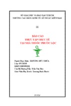
Man's achievements in Structural Engineering are most evident in the world's largest bridge
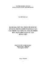
spans. Today the suspension bridge reaches a free span of almost 2000m (Akashi-Kaikyo
Bridge, Japan) while its cable-stayed counterpart can cross almost 1000m (Tatara Bridge, Japan,
Normandie Bridge, France, Figure 1). Cable-supported bridges therefore play an important role
in the overcoming of barriers that had split people, nations and even continents before.
Figure 1:
Normandie Bridge, France
It is evident that they are an important economical factor as well. By cheapening the supply of
goods they contribute significantly to economical prosperity.
Cable-stayed bridges, in particular, have become increasingly popular in the past decade in the
United States, Japan and Europe as well as in third-world countries. This can be attributed to
several advantages over suspension bridges, predominantly being associated with the relaxed
foundation requirements. This leads to economical benefits which can favour cable-stayed
bridges in free spans of up to 1000m.
Many of the big cable-stayed bridge projects have been executed in a seismically active environment like Japan or California. However, very few of them have so far experienced a strong
earthquake shaking and measurements of seismic response are scarce. This enforces the need for
accurate modelling techniques. Three methods are available to the engineer to study the
dynamic behaviour: forced vibration tests of real bridges, model testing and computer analysis.
The latter approach is becoming increasingly important since it offers the widest range of possible parametric studies. However, testing methods are still indispensable for calibration purposes.
Herein the seismic behaviour of the Rion-Antirion cable-stayed Bridge, Greece, is studied by
means of computer analyses employing the finite element method. A framework of performance
criteria is set up and within this different possible structural configurations are investigated.
Conclusions are drawn regarding the effectiveness of deck isolation devices.
Introduction
Page 7
1.2 Significance of long-span bridges
1.2.1
Impact of bridges on economy
Roads and railways are the most important means of transport in all countries of the world. They
act as lifelines on which many economic components depend. Naturally rivers, canals, valleys
and seas constitute boundaries for these networks and therefore considerably confine the
unopposed supply of goods. They cause significant extra costs because goods have to be
diverted or even shipped or flown. These extra costs can exclude economies from foreign
markets.
It is evident that in this situation bridging the gap is worth considering. Cable-supported bridges
offer the possibility to cross even very large distances without intermediate supports. Hence, it is
only since their development, that people can consider crossings like the Bosporus (Istanbul Anatolia, completed 1973 and 1988), Öresund (Denmark - Sweden, to be completed 2000), the
Strait of Messina (mainland Italy - Sicily, design stage finished), the Strait of Gibraltar (Spain Morocco) or the Bering Strait (Alaska - Russia).
Of course infrastructure projects like these are costly. Countries take up high loans to afford
these road links. Cost-benefit analyses are inevitable as proof for banks. However, the number
of already executed major projects emphasises that even the exorbitant costs can be worthwhile.
The bridges become an important factor for the whole region and can significantly boost the
industry on both sides of the new link.
Furthermore and equally importantly, those bridge projects can become a substantial factor in
the cultural exchange among people.
1.2.2
The trans-European transport network
The European Parliament has on the 23 July 1996 introduced plans for the development of a
"trans-European transport network" ([29]). This project comprises infrastructures (roads,
railways, waterways, ports, airports, navigation aids, intermodal freight terminals and product
pipelines) together with the services necessary for the operation of these infrastructures.
Investments of about 15 billion Euro per year in rail and road systems alone underline the
remarks made in the previous section regarding the importance of transport networks and the
links within them.
The objectives of the network were defined by the European Parliament as follows:
-
ensure mobility of persons and goods;
offer users high-quality infrastructures;
combine all modes of transport;
allow the optimal use of existing capacities;
be interoperable in all its components;
cover the whole territory of the Community;
allow for its extension to the EFTA Member States, countries of Central and Eastern
Europe and the Mediterranean countries.
Introduction
Page 8
Some of the broad lines of Community action concern:
-
the development of network structure plans;
the identification of projects of common interest;
the promotion of network interoperability;
research and deve lopment,
with priority measures defined as follows:
-
completion of the connections needed to facilitate transport;
optimization of the efficiency of existing infrastructure;
achievement of interoperability of network components;
integration of the environmental dimension in the network.
It is apparent that the connections as means of interoperation between sub-networks are one of
the most important components within the network. Many of the currently planned major
bridges in Europe are therefore part of the network and supported by the EU. Among them are
the Öresund and Rion-Antirion Bridges which are discussed subsequently.
1.3 Recent cable-stayed bridge projects
1.3.1
Öresund Bridge, Sweden
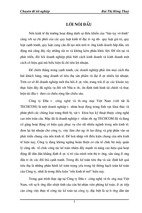
The £1.3 billion Öresund crossing will link Denmark and Sweden from the year 2000 on. It
comprises an immersed tunnel, an artificial island and a bridge part of which is a cable-stayed
bridge (Figure 2).
Figure 2:
Öresund Bridge, Sweden
For a combined road and railway cable-stayed bridge the center span of 490m (8th largest cablestayed bridge in the world) is remarkable. A steel truss girder of dimensions 13.5x10.5m was
Introduction
Page 9
employed to accommodate road and railway traffic on two levels. The concrete slab is 23.5m
wide and provides space for a 4 lane motorway.
The structurally more difficult harp pattern (see section 2.1.2.1) was chosen for aesthetic
reasons. It should be mentioned that the struts of the girder were inclined according to the angle
of the cables which is favourable from the structural as well as pleasing from the aesthetic point
of view.
The money for the project was borrowed on the international market and jointly guaranteed by
the governments of Denmark and Sweden. It will be paid back from the toll fees introduced.
Being part of the trans-European transport network the link will be one of the most important
European Structures carrying railway and at least 11,000 vehicles per day.
More information on the Öresund project can be found in [91].
1.3.2
Tatara Bridge, Japan
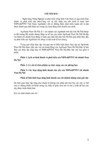
Upon completion in 1999 the Tatara Bridge will be the cable-stayed bridge with the longest free
span in the world. It is shown in Figure 3, an elevation is given in section 2.1, Figure 5. The
center span is 890m, supported by a semi-fan type cable system. Compared with this the side
spans with 270 and 320m are extremely short and asymmetric so that intermediate piers and
counterweights needed to be applied there.
Figure 3:
Tatara Bridge, Japan
The girder is a steel box section with a streamlined shape to decrease wind forces. It is 31m
wide and only 2.70m deep. To act as counterweight the deck in parts of the sidespans is made of
concrete. At the towers the girder is kept free because of high temperature induced forces in the
case of a fixing.
In model tests it was found to be necessary to install additional damping devices for the cables.
Particularly the upper ones (the longest one having a length of over 460 m - the longest stay
cable ever) were found to be prone to wind and rain induced vibration. Additional ropes
Introduction
Page 10
perpendicular to the stay cables were installed and connected to damping devices at the deck.
This yielded cable damping ratios of over 2% of critical.
The Tatara Bridge is being constructed in an area of high seismicity. It was designed for an
earthquake event of magnitude 8.5 at a distance of 200km. The fundamental period of the bridge
is 7.2s being associated with a longitudinal sway mode.
All information about the Tatara Bridge were taken from [33].
1.3.3
The Higashi-Kobe Bridge, Japan
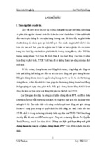
The Higashi-Kobe Bridge in Kobe City, Japan, is one of the busiest bridges in the world. As part
of the Osaka Bay Route it spans the Higashi-Kobe Channel connecting two reclaimed land areas
(Figure 4).
Figure 4:
Higashi-Kobe Bridge, Japan
The bridge's main span is 485m with the side span being 200m each. The main girder is a
Warren truss with height a of 9m. It accommodates 2 roads at the top and bottom of the truss
respectively. Both of these have three lanes, the width of the truss being 16m.
For the cable system the harp pattern was chosen. The steel towers are of the H-shape and have
a height of 146.5m. These are placed on piers which are founded on caissons of size 35 (W) x
32 (L) x 26.5 (H) m.
An important feature of the bridge is that the main girder can move longitudinally on all its
supports. This results in a very long fundamental period which was found to be favourable for
the seismic behaviour.
On 17 January 1995 Kobe was struck by an earthquake of magnitude 7.2. Although the HigashiKobe Bridge performed well in this earthquake, certain damage did occur which was reported in
[44]. Important information about the soil behaviour could be obtained from this event because
the bridge was instrumented. These will be further discussed in section 2.3.3.
State of Research on Cable-Stayed Bridges
Page 11
2 STATE OF RESEARCH ON CABLE-STAYED BRIDGES
2.1 Configuration of Cable-Stayed Bridges
In this section a brief overview of the structural configuration and the load resisting mechanisms
of cable-stayed bridges is given. This is necessary because they are in many ways distinctly
different from beam-type bridges and these differences strongly affect their behaviour under
static as well as dynamic loads. It has to be noted that herein only the current trend of design can
be described. An outline of the evolution of cable-stayed bridges and more elaborate
information can be found elsewhere: [50], [87].
2.1.1
General remarks
Cable-stayed bridges present a three-dimensional system consisting of the following structural
components, ordered according to the load path:
- stiffening girder,
- cable system,
- towers and
- foundations.
The stiffening girder is supported by straight inclined cables which are anchored at the towers.
These pylons are placed on the main piers so that the cable forces can be transferred down to the
foundation system. As an example the configuration of the Tatara Bridge is given in Figure 5.
Figure 5:
Tatara Bridge, Japan, elevation
It is apparent from the picture that the close supporting points enable the deck to be very slim.
Even though it has to support considerable vertical loads, it is loaded mainly in compression
with the largest prestress being at the intersection with the towers. This is due to the horizontal
force which is applied by each of the cables. This characteristic also distinguishes the cablestayed bridge from the suspension bridge because necessary provisions for anchoring cables are
much more relaxed. Often cable-stayed bridges are even constructed as being self-anchored.
The particular components of this bridge type will now be discussed in more detail. However, if
more comprehensive information are sought the reader is referred to [50] and [87].
State of Research on Cable-Stayed Bridges
2.1.2
Page 12
Cable System
2.1.2.1 Cable patterns
The cable system connects the stiffening girder with the towers. There are essentially 3 patterns
which are used:
- fan system,
- harp system and
- modified fan system.
These are depicted in Figure 6. All of these patterns can be used for single as well as for double
plane cable configurations.
Figure 6:
Cable patterns in cable-stayed bridges ([50])
In the fan system all cables are leading to the top of the tower. Structurally this arrangement is
usually considered the best, since the maximum inclination of each cable can be reached. This
enables the most effective support of the vertical deck force and thus leads to the smallest
possible cable diameter.
The fan system causes severe detailing problems for the configuration of the anchorage system
at the tower. The modified fan system overcomes this problem by spreading the anchorage
points over a certain length. If this length is small, the behaviour is not significantly altered.
The stay cables are an important part of the bracing system of the structure. It was found that
their stiffness is highest when the cable planes are inclined from the vertical. This favours Ashaped towers with all the cables being attached to one point or line at the top.
In the harp system the cables are connected to the tower at different heights and placed parallel
to each other. This pattern is deemed to be more aesthetically pleasing because no crossing of
cables occurs even when viewing from a diagonal direction (in contrast see Figure 1). However,
this system causes bending moments in the tower and the whole configuration tends to be less
stable. However, excellent stiffness for the main span can be obtained by anchoring each cable
to a pier at the side span as was done for the Knie Bridge, Germany ([87]).
Most of the recent cable-stayed bridges, particularly the very long ones, are of the modified fan
State of Research on Cable-Stayed Bridges
Page 13
type with A-shaped pylons for the discussed reasons. However, there are still many variations
regarding the configuration of the abutments, piers and towers and their respective connection
with the stiffening girder. These problems will be discussed subsequently in the light of the
dynamic behaviour.
2.1.2.2 Types of cables
The success of cable-stayed bridges in recent years can mainly be attributed to the development
of high strength steel wires. These are used to form ropes or strands, the latter usually being
applied in cable-stayed bridges.
There are 3 types of strand configuration:
- helically-wound strand,
- parallel wire strand and
- locked coil strand.
Figure 7 shows these arrangements.
Figure 7:
Helically-wound, parallel wire and locked coil cable strands ([50])
The first two types are composed of round wires. Helically-wound strands comprise a centre
wire with the other wires being formed around it in a helical manner. They have a lower
modulus of elasticity than their parallel counterparts and furthermore experience a considerable
amount of self-compacting when stressed for the first time.
Locked coil strands consist of three layers of twisted wire. The core is a normal spiral strand. It
is surrounded by several layers of wedge or keystone shaped wires and finally several layers of
Z- or S-shaped wires. The advantages of this type of cable are a more effective protection
against corrosion and more favourable properties compared with the previous arrangements.
First, the density is 30% higher, thus enabling slimmer cables which are less sensitive to wind
impact. Second, their modulus of elasticity is even 50% higher compared with a normal strand
of same diameter. Third, they are largely insensitive to bearing pressure because of a better
interaction of the individual wires.
The vast majority of modern cable-stayed bridges use galvanised locked-coil wire strands. These
are assembled to the large diameter cables, which are usually parallel strand cables.
State of Research on Cable-Stayed Bridges
Page 14
2.1.2.3 Anchorage of cables
Cables need to be anchored at the deck as well as at the towers. For each of these connections
numerous devices exist depending on the configuration of deck and tower as well as of the
cable. Exemplary, some arrangements for tower and deck are shown in Figure 8 and Figure 9
respectively.
Figure 8:
Devices for cable anchorage at the tower ([87])
Figure 9:
Devices for cable anchorage at the deck ([50])
Cable supports at the tower may be either fixed or movable. They are situated at the top or at
intermediate locations mainly depending on the number of cables used. While fixed supports are
either by means of pins or sockets, movable supports have either roller or rocker devices.
Connections to the deck are by means of special sockets. Their configuration strongly depends
on the type of cable used. Usually these sockets are threaded and a bolt is used to allow
adjustments on the tension of the cable.
2.1.3
Stiffening Girder
The role of the stiffening girder is to transfer the applied loads, self weight as well as traffic
load, into the cable system. As mentioned earlier, in cable-stayed bridges these have to resist
considerable axial compression forces beside the vertical bending moments. This compression
force is introduced by the inclined cables.
The girder can be either of concrete or steel. For smaller span lengths concrete girders are
usually employed because of the good compressional characteristics. However, as the span
State of Research on Cable-Stayed Bridges
Page 15
increases the dead load also increases, thus favouring steel girders. The longest concrete bridge
that has been constructed is the Skarnsund Bridge, Norway, with a main span of 530 m ([58]).
Also composite girders have been extensively used, entering the span range above 600 m.
The shape of the stiffening girder depends on the nature of loads it has to resist. In the design of
very long-span bridges aerodynamic considerations can govern the decision. These are beyond
the scope of this work but brief account of this issue will be given. It was shown in [41], that
bluff cross sections which have a higher drag coefficient, experience considerably higher
transverse wind forces than less angular sections. Specially designed streamlined sections can
also avoid the creation of wind-turbulence at the downstream side, a phenomenon referred to as
vortex-shedding. Considerable affords are therefore made to account for these circumstances.
For the Tatara Bridge these were reported in [33].
There are three types of girder cross sections used for cable-stayed bridges:
- longitudinal edge beams,
- box girders and
- trusses.
These are shown in Figure 10.
a)
b)
c)
Figure 10: Girder cross-sections: a) simple beam arrangement (Knie Bridge,
Germany), b) box section (Oberkasseler Bridge, Germany),
c) truss (Öresund Bridge, Sweden) ([50])
State of Research on Cable-Stayed Bridges
Page 16
Beam arrangements consist of a steel or concrete deck which is supported by either a steel or a
concrete beam. The beams carry the loads to the cables where they are anchored. Although easy
to construct and generally efficient, beam-type girders have only a small torsional stiffness
which can be undesirable depending on the structural system.
Box sections possess high torsional stiffness and can be formed in a streamlined shape thus
showing best behaviour under high wind impact. However, there are numerous possible shapes
and the choice depends on the distances between the supports, the desired width of the section,
the type of loading and the cable pattern.
Trusses have been used extensively in the past. They possess similar torsional stiffnesses as box
sections. The aerodynamic behaviour is generally good. Trusses are of steel and thus the
stiffness is high with respect to the weight. However, the high depth of the section can be
criticised for aesthetic reasons. Trusses are unrivalled if double deck functionality is desired. In
this case the railway deck can be accommodated at the bottom chord.
2.1.4
Towers
The function of the towers is to support the cable system and to transfer its forces to the
foundation. They are subjected to high axial forces. Bending moments can be present as well,
depending on the support conditions. It has already been pointed out that the towers in harp-type
bridges are subjected to severe bending moments. Box sections with high wall widths generally
provide best solutions. They can be kept slender and still possess high stiffnesses.
Towers can be made of steel or concrete. Concrete towers are generally cheaper than equivalent
steel towers and have a higher stiffness. However, their weight is considerably higher and thus
the choice also depends on the soil conditions present. Furthermore, steel towers have
advantages in terms of construction speed.
The shape of the towers is strongly dependent on the cable system and the applied loads but
aesthetic considerations are important as well. Possible configurations are depicted in Figure 11.
Figure 11: Tower configurations: H-, A- and λ-shapes ([50])
State of Research on Cable-Stayed Bridges
Page 17
While I- and H-shapes are vertical tower configurations and therefore support vertical cable
planes, A- and λ-shaped towers correspond to inclined cable planes. The influence of these
patterns on the overall stiffness of the structure have been discussed earlier. As far as the
stiffness of the tower itself is concerned, A- and λ-shapes are preferable. However, their
structural configuration is significantly different from the I- and H-shape which can have
adverse effects on the ductility (cf. section 5.1.2).
2.1.5
Foundations
Foundations are the link between the structure and the ground. Their configuration is mainly
influenced by the soil conditions and the load acting.
For cable-stayed bridges often pile foundations are used, with the pier being connected to the
pile cap. Various arrangements are possible and the choice mainly depends on the magnitude of
the overturning moment.
Cable-stayed bridges often need to be founded in water. In this case caisson foundations are
used. The caisson acts as a block and can be placed either on the sea bed or, again, on piles.
2.2 Nonlinearities in Cable-Stayed Bridges
Cable-stayed bridges have an inherently nonlinear behaviour. This has been revealed by very
early studies and shall be discussed in detail here because the nonlinearity is of greatest
importance for any kind of analysis.
Nonlinearities can be broadly divided in geometrical and material nonlinearities. While the latter
depend on the specific structure (materials used, loads acting, design assumptions), geometric
nonlinearities are present in any cable-stayed bridge.
Geometric nonlinearity originates from:
- the cable sag which governs the axial elongation and the axial tension,
- the action of compressive loads in the deck and in the towers,
- the effect of relatively large deflections of the whole structure due to its flexibility
([1], [4], [9], [50], [52], [73], [74], [75], [87], [88]).
It is well known from elementary mechanics that a cable, supported at both ends and subjected
to its self weight and an externally applied axial tension force, will sag into the shape of a
catenary. Increasing the axial force not only results in an increase in the axial strain of the cable
but also in a reduction of the sag which evidently leads to a nonlinear stress-displacement
relationship. The influence of the cable sag on its axial stiffness has first been analytically
expressed by Ernst ([34]). If an inclined cable under its self weight is considered, an equivalent
elastic modulus can be calculated as follows:
State of Research on Cable-Stayed Bridges
Ee =
Page 18
E
(1)
(w ⋅ l )2 E
1+
12σ 3
where: Ee
E
w
l
σ
is the effective modulus of elasticity of the sagging cable,
is the modulus of elasticity of the cable which is taut and loaded vertically,
is the unit weight of the cable,
is the horizontal projection of the cable length and
is the prevailing cable tensile stress.
This relationship can be easily implemented in nonlinear computer codes.
It is interesting to note that the above described cable behaviour leads to an increase in the
bridge stiffness if the forces are increased. This is depicted in Figure 12 and clearly distinguishes cable-supported structures from standard structures. They can be classified as being of
the geometric-hardening type ([2], [4], [5]).
Generalized
Force
CABLE-STAYED BRIDGES
Non-cable Structures
Cable Structures
Generalized
Displacement
Figure 12: Nonlinearities in cable-stayed bridges
Today most finite element programs offer nonlinear solution algorithms. With these it is
possible to take the above mentioned characteristics of cable-stayed bridges into account. The
nonlinear cable behaviour can be either treated utilising Ernst's formula or applying multielement cable-formulations. This issue will be further discussed in section 2.3.1.
The nonlinear behaviour of the tower and girder elements due to axial force-bending moment
interaction is usually accounted for by calculating an updated bending and axial stiffness of the
elements. Detailed descriptions of nonlinear element formulations can be found in [32], [57],
[107] and elsewhere.
The overall change in the bridge geometry as third source of nonlinearity can be accounted for
by updating the bridge geometry by adding the incremental nodal displacements to the previous
nodal coordinates before recomputing the stiffness of the bridge in the deformed shape ([74]).
State of Research on Cable-Stayed Bridges
Page 19
2.3 Dynamic behaviour and earthquake response
2.3.1
General dynamic characteristics
Long-span cable-supported bridges, due to their large dimensions and high flexibility, usually
have extremely long fundamental periods. This distinguishes them from most other structures
and strongly affects their dynamic behaviour. However, the flexibility and dynamic characteristics depend on several parameters such as the span, the cable system and the support
conditions. These will be discussed in detail here.
The dynamic behaviour of a structure can be well characterised by a modal analysis. The linear
response of the structure to any dynamic excitation can be expressed as superposition of its
mode shapes. The contribution of each mode depends on the frequency content of the excitation
and on the natural frequencies of the modes of the structure.
The results of modal analyses of cable-stayed bridges can be found in most of the research
papers dealing with their seismic behaviour. In Figure 13 the first modes obtained by AbdelGhaffar for a model bridge in [1] are shown. The first modes of vibration have very long periods
of several seconds and are mainly deck modes. These are followed by cable modes which are
coupled with deck modes. Tower modes usually are even higher modes and their coupling with
the deck depends on the support conditions between these. The influence of different support
conditions on the mode distribution has been investigated by Ali and Abdel-Ghaffar in [9]. It is
apparent from the resulting diagram shown in Figure 14 that movable supports lead to a more
flexible structure, thus shifting the graph towards longer periods. As an example, in [44] it was
mentioned by Ganev et al that the Higashi-Kobe Bridge has been deliberately designed with
longitudinally movable deck in order to shift the fundamental period to a value of low spectral
amplification. The decision upon the support conditions of the deck is usually governed by
serviceability as well as earthquake considerations. A restrained deck will avoid excessive
movements due to traffic and wind loading and may thus be preferred. However, in the case of
an earthquake a restrained deck will generate high forces which are applied to the pier-pylon
system. It is thus a trade-off and often intermediate solutions are sought. Elaborate investigations on possible damping solutions are discussed subsequently in this report.
Usually the modes obtained are classified in their directional properties. Thus, vertical,
longitudinal, transverse and torsional modes are distinguished and the order of these well
characterises the bridge behaviour without the need to depict the individual mode shapes. As an
example the first 25 modes of the Quincy Bayview Bridge, US, are given in Table 1. They have
been identified experimentally as will be discussed later.
State of Research on Cable-Stayed Bridges
Page 20
Figure 13: First six computed mode shapes (considering one-element cable
discretisation) ([1])
Figure 14: Effect of support conditions on the natural periods ([9])
Typical for cable-stayed bridges is a strong coupling (such as bending-torsion coupling) in the
three orthogonal directions as can also be seen in Table 1. This coupled motion distinguishes
cable-stayed bridges from suspension bridges for which pure vertical, lateral and torsional
- Xem thêm -