VIETNAM NATIONAL UNIVERSITY, HANOI
COLLEGE OF TECHNOLOGY
Phan Huu Phu
SENSING MICROGRIPPER
WITH PID CONTROL SYSTEMS
MASTER THESIS
Hanoi - 2008
VIETNAM NATIONAL UNIVERSITY, HANOI
COLLEGE OF TECHNLOGY
Phan Huu Phu
SENSING MICROGRIPPER
WITH PID CONTROL SYSTEMS
Major: Electronics and Telecommunications Technology
Concentration: Electronics Engineering
Code: 60 52 70
MASTER THESIS
SUPERVISOR:
Dr. Chu Duc Trinh
Hanoi - 2008
2
TABLE OF CONTENTS
DECLARATION......................................................................................................................1
ACKNOWLEDGEMENTS.....................................................................................................4
ABSTRACT..............................................................................................................................5
LIST OF ABBREVIATIONS .................................................................................................6
CHAPTER 1 INTRODUCTION ............................................................................................7
1.1 MANIPULATION IN MICRO-WORLD ................................................................................................................7
1.2 MICRO-GRIPER FOR MICRO-MANIPULATION ..................................................................................................7
1.2.1 Electrostatic microgripper ...................................................................................................................7
1.2.2 Piezoelectric microgripper...................................................................................................................8
1.2.3 Electrothermal microgripper................................................................................................................8
1.2.4 Polymeric electrothermal microgripper .............................................................................................10
1.3 MICRO-MANIPULATION WITH A FEEDBACK SYSTEM ....................................................................................11
1.3.1 Force sensor .......................................................................................................................................11
1.3.2 Sensing microgripper .........................................................................................................................14
CHAPTER 2 SENSING MICROGRIPPER .......................................................................17
2.1 INTRODUCTION ...........................................................................................................................................17
2.2 FORCE-SENSING CANTILEVER......................................................................................................................17
2.3 SILICON-POLYMER ELECTROTHERMAL MICROGRIPPER................................................................................18
2.4 SENSING MICROGRIPPER ..............................................................................................................................20
2.5 THE SENSING MICROGRIPPER CHARACTERISTICS .........................................................................................22
2.5.1 Electrothermal actuator characteristics.............................................................................................22
2.5.2 Sensing cantilever beam characteristics ............................................................................................25
2.5.3 Response frequency of the sensing microgripper ...............................................................................27
CHAPTER 3 BUILDING PID CONTROL FUNCTION ..................................................29
3.1 FEEDBACK LOOP CONTROL ..........................................................................................................................29
3.2 BUILDING A PID TRANSFER FUNCTION FOR THE SENSING MICROGRIPPER SYSTEM ......................................30
3.2.1 Transfer function of sensing microgripper .........................................................................................30
3.2.2 Transfer function of driver circuit ......................................................................................................30
3.2.3 Open-loop control ..............................................................................................................................31
3.2.4 Proportional control...........................................................................................................................32
3.2.5 Proportional – Integral control..........................................................................................................32
3.2.6 Proportional – Derivative control......................................................................................................33
3.2.7 Proportional – Derivative – Integral control .....................................................................................34
CHAPTER 4 ELECTRICAL DESIGN ...............................................................................35
4.1 INTRODUCTION ...........................................................................................................................................35
4.2 PROCESS SELECTION AND SIMULATION .......................................................................................................35
4.2.1 Process selection ................................................................................................................................35
4.2.2 Device modeling .................................................................................................................................36
4.2.3 Silicon-level simulation ......................................................................................................................36
4.2.4 Analog-only simulation ......................................................................................................................38
4.2.5 Mixed Analog/Digital simulation .......................................................................................................38
4.3 SYSTEM BLOCK DIAGRAM ...........................................................................................................................39
4.4 CELLS DESIGN .............................................................................................................................................40
4.4.1 Voltage reference generator...............................................................................................................40
4.4.2 Internal regulator ...............................................................................................................................45
4.4.2.1 The regulator:............................................................................................................................................... 45
4.4.2.2 The high temperature detector: .................................................................................................................... 46
4.4.2.3 The UVLO................................................................................................................................................... 47
4.4.2.4 Bias current generator.................................................................................................................................. 47
4.4.3 Digital to Analog converter (DAC) ....................................................................................................52
4.4.4 Buffer..................................................................................................................................................56
4.4.5 PID Controller ...................................................................................................................................56
4.4.6 Other cells ..........................................................................................................................................60
4.5 FULLY SCHEMATIC OF SYSTEM AND SIMULATION RESULTS .........................................................................62
3
4.5.1 Schematic ...........................................................................................................................................62
4.5.2 Simulation results ...............................................................................................................................62
CHAPTER 5 PHYSICAL DESIGN .....................................................................................65
5.1 INTRODUCTION OF LAYOUT ........................................................................................................................65
5.1.1 Matching concepts..............................................................................................................................65
5.1.2 MOS transistor layout ........................................................................................................................66
5.1.3 Resistor layout....................................................................................................................................68
5.1.4 Capacitor layout.................................................................................................................................69
5.1.5 Layout rules........................................................................................................................................70
5.2 SYSTEM FLOOR PLAN ..................................................................................................................................71
5.3 SYSTEM LAYOUT .........................................................................................................................................72
5.3.1 Sensing microgripper .........................................................................................................................72
5.3.2 Electrical circuits ...............................................................................................................................72
CHAPTER 6 CONCLUSION & FUTURE WORKS.........................................................74
6.1 CONCLUSION ...............................................................................................................................................74
6.2 FUTURE WORKS ...........................................................................................................................................74
6.2.1 Finishing the system layout ................................................................................................................74
6.2.2 Process establishment ........................................................................................................................74
6.2.3 Layout verification .............................................................................................................................75
6.2.4 Sample fabrication .............................................................................................................................75
6.2.5 Characterization.................................................................................................................................75
BIBLIOGRAPHY ..................................................................................................................76
6
List of Abbreviations
AFM: Atomic Force Microscope
AlN: Aluminum Nitride
Bi-CMOS: Bipolar junction transistors and CMOS technology
CAD: Computer Aid Design
CMOS: Complementary Metal-Oxide-Semiconductor
CTE: Thermal expansion coefficient
DAC: Digital-to-Analog Converter
DC: Direct Current
DIMES: Delft Institute of Microsystems and Nanoelectronics
DOFs: Degrees(s) of Freedom
DRC: Design Rules Checking
ERC: Electrical Rules Check
ESD: Electro Static Discharge
FIB-cut: Focused ion beam-cut
GDSII: Graphic Data System II
IC: Integrated Circuits
LSB: Least Significant Bit
LSI: Large-Scale Integration
LVS: Layout versus Schematic
MEMS: Micro-Electro-Mechanical systems
MIS: Minimally Invasive Surgery
MOSFET: Metal-Oxide Semiconductor Field-Effect Transistor
NMOS: N-channel Metal-Oxide Semiconductor Field-Effect Transistor
PID: Proportional Integral Derivative
PLI: Photolithographic Invariance
PMOS: P-channel Metal-Oxide Semiconductor Field-Effect Transistor
PSRR: Power supply rejection ratio
PTAT: Proportional to Absolute Temperature
PVDF: Polyvinylidene Flouride
PZT: Lead Zirconate Titanate
SEM: Scanning Electron Microscope
SOI: Silicon on Insulator
SPICE: Simulation Program Integrated Circuit Emphasis
TC: Temperature Coefficients
UVLO: Under Voltage Lock-Out
ZnO2: Zinc peroxide
7
Chapter 1 Introduction
1.1 Manipulation in micro-world
The dominant physical principles in the micro-world can be quite difference from
those of the macro-world. When the size of the object is less than 1mm, adhesive
forces between the manipulation tool and the object such as surface tension,
electrostatic and van der Waals forces can be significant compared to the gravitational
force [23].
Manipulation of micro-particles can be done using several physical principles and
methods. For manipulation of a micro-structure under specific ambient conditions or
liquid; suction, cryogenic, electrostatic, and friction are the most often considered
methods.
Friction principle is chosen for addressing the micro-manipulation of small objects
presented in this thesis. Like the human hand, friction manipulation uses at least two
fingers applies on two sides of a clamped object. A friction manipulator can old an
object due to the friction force between the tools and the object surfaces. This friction
method is the most widely used in micro-manipulation because of size, cost,
reliability, and fabrication aspect in particular.
1.2 Micro-griper for micro-manipulation
In the recent years, microgrippers have been widely researched as they are in great
demand in many research and application areas, such as advanced micro-assembly,
micromanipulation, micro-robotic, minimally invasive and living cell surgery. For the
development of microgrippers fabricated using integrated circuits (IC) or IC
compatible technology, electrostatic, piezoelectric and electro-thermal actuation are
generally used.
1.2.1 Electrostatic microgripper
The electrostatic principle is based on the distance change between a fixed electrode
and a suspended one when the voltage applied to these two electrodes changes. The
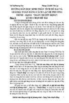
first successful electrostatic microgripper based on bulk and surface silicon micromachining techniques was presented in 1992 (see Fig. 1.1) [3]. The 12 µm thick and
1500 µm long polysilicon microgripper is overhanging from a supporting silicon
cantilever. The microgripper jaw displacement is 10 µm at an applied voltage of 45 V,
with a basic frequency of 5 kHz. A monolithically fabricated electrostatic
microgripper has been recently presented [7]. A lateral comb drive has been chosen to
actuate this gripper. This microgripper can manipulate glass or copolymer spheres of
size ranging from 20 to 90 µm with an applied force up to 380 µ at an applied voltage
of 140 V. The main limitation of this device is the high voltage, the large size and the
complicated electronic circuit typical of the electrostatic method.
8
Figure 1.1: The schematic design of a polysilicon electrostatic microgripper (adapted from [3])
1.2.2 Piezoelectric microgripper
Piezoelectric materials (such as PZT, AIN, and ZnO2) are capable of producing stress
and/or strain when an electric field is applied. Piezoceramic elements have been used
to build microgrippers (see Fig. 1.2) [22]. However, piezoelectric actuator fabrication
processes are generally not IC compatible and are difficult to miniaturize.
Piezoelectric actuators also require a high actuation voltage and produce small
displacements.
Figure 1.2: Schematic drawing of a piezoelectric microgripper [22].
1.2.3 Electrothermal microgripper
A thermostat consist a bi-metallic strip, which is made of two thin metallic pieces of
difference materials that are bonded together. As the temperature of the strip changes,
two pieces change length at difference rates, forcing the strip to bend. Based on the
9
Timoshenko’s bi-metal thermostat theory, an electrothermal microgripper (see Fig.
1.3) is fabricated using doped silicon and a special bonding technique [9]. This
structure consists of a silicon cantilever beam with a doped layer on top. Out of plane
bending is obtained when a current is induced though the doped layer.
Figure 1.3: Schematic drawing of a typical bi-material cantilever actuator. The doped-silicon expands
when applying a current, therefore the cantilever bends downwards (adapted from [9]).
Figure 1.4: Schematic drawing of a typical flexure actuator: (a) single hot arm configuration and (b)
two hot arms configuration
10
Figure 1.5: A microgripper product of Zyvex company: (a) the entire device is about 650 µm long,
270 µm wide, 50 µm thick. The initial gap between the two jaws is 36 µm and the maximum opening is
80 µm; [(b) and (c)] the grippers being used to manipulate a FIB-cut coupon [13].
Since the well-known flexure thermal actuator (see Fig. 1.4(a)) was introduced in
1992 [10], the actuator has received wide interest as they can produce a large
displacement, a large force and use IC compatible fabrication process. The flexure
thermal actuator consists of a thin arm with higher electrical resistance than its thick
arm. The thin arm (hot arm) gets more heat than the thick one and consequently
elongates more than the thick arm and in-plane bending occurs. A configuration more
efficient in terms of power consumption uses two hot arm thermal actuators (see Fig.
1.4(b)). The electrical current just passes through two hot arms. As there is no
electrical current in cold arm and flexure, the efficiency of power consumption is
improved compared with the single hot arm structure. This principle is also used in the
Zyvex gripper shown in Fig. 1.5. The limitations of these devices are the extremely
high operating temperature and high power consumption.
1.2.4 Polymeric electrothermal microgripper
Recently, polymeric electrothermal microgrippers have been extensively researched as
they are capable of producing large displacements at a lower drive voltage and
operating temperature [19]. Based on the above-mentioned flexure thermal actuator,
polymeric microgrippers are developed using a polymer layer with a thin metal heater
on top [19]. The structures have a large displacement at low operational temperature
and low power consumption due to the large thermal expansion coefficient (CTE) of
the polymer. Fig. 1.6 shows the schematic design of a developed polymeric
microgripper using SU8 with a thin metal layer (Cr/Au) on top as a heater [19]. The
microgripper jaw displacement is 12 µm at an applied voltage of about 2 V and an
operational temperature of less than 100 0C. This microgripper has been designed to
manipulate cells in air and also in fluid solutions.
11
In these polymeric microgrippers the metal heater is deposited on top of a high
thermal expansion coefficient polymer layer. The interface between the heat source
and the polymer layer is limited by the surface area of the metal layer, and the heat
transfer along the vertical dimension is not effective. Since the polymer layers have
low thermal conductivity, these devices can generate limited movement. Moreover,
the unintentional vertical movement couples and interferes with the desired lateral
movement [19].
Figure 1.7: Schematic drawing of a fabricated SU8 microgripper (adapted from [19]).
1.3 Micro-manipulation with a feedback system
When manipulating micro-objects, operating on living cells or in minimally invasive
surgery (MIS), enhanced dexterity, accuracy and speed are considerably improved
when the force on the objects can be sensed and controlled in real-time.
The development of miniaturized manipulators with force control is also of great
interest in micro-robotics and micro-assembly.
Manipulation of micro-objects with traditional microgrippers without a built in force
sensor normally requires a camera inserted into the system to obtain visual feedback.
This approach results in a two-dimensional image. Depth perception of the contact
between the manipulating tool and the object being manipulated is lost, making it
difficult to identify the position of the tool [16]. Moreover only displacement, and not
force, can be detected. A microgripper with a built-in force sensor can address this
limitation and is therefore suitable for holding objects firmly, whilst avoiding any
squeezing of delicate objects.
1.3.1 Force sensor
The contact forces between living cells in a laboratory or between micro-particles and
a manipulator are generally in the nano-Newton to mili-Newton range. Cantilever
force sensors are generally used to measure force in this range.
12
The bending of the cantilever is related to the applied force. By monitoring the
deflection of the beam, the amplitude of the applied force can be detected. Several
force-sensing methods, such as capacitive, piezoelectric, optical laser detection, and
piezoresistive can be used [30].
The capacitive method is based on the capacitance change which occurs when the
structure is deformed, and is widely used in micro-accelerometers and harsh
environment sensors. An example of a capacitive force sensor (see Fig. 1.8) is shown
in [29]. It has two degrees of freedom (2-DOF) and uses silicon on insulator (SOI)
wafers. This sensor is capable of measuring forces up to 490 µN with a resolution of
0.01 µN along the x -axis and up to 900 µN with resolution of 0.24 µN along the yaxis. Complete isolation between the two electrodes is a limitation of capacitive force
sensors, so normally SOI wafers are used. Alternatively, trench isolation can be used.
However, it is difficult to control the etching area to obtain a completely isolated
structure. Moreover, the capacitive method requires a complicated fabrication process
and complex electronic circuitry.
Figure 1.8: Schematic drawing of a capacitive force sensor in two dimensions (adapted from [29]).
A two-dimensional piezoelectric force sensor is presented in [28] (see Fig. 1.9). It
consists of two perpendicular pieces of polyvinylidene fluoride (PVDF) material. This
structure is symmetric in the vertical and lateral dimensions, with resolution and
sensitivity in the µN range. However, the PVDF cannot be patterned optically. The
two pieces have to be glued perpendicularly to each other, resulting in a rather large
sensor structure. With this approach, the sensor cannot be miniaturized and the
fabrication process is not IC-compatible. The piezoelectric method also requires
complicated electronic circuits for processing the signal.
Cantilevers based on optical force measurement are often used in atomic force
microscopy (AFM) and high-resolution measurement. With this principle, the
deflection of a cantilever is amplified by a laser beam reflected on to the cantilever tip,
and monitored using a split photodiode detector. This principle is very powerful for
13
measuring small displacements but requires high accuracy of optical alignment and
adjustment. The cantilever surface must be reflective and larger than the laser beam
spot. It is not easy to create a lateral and multidimensional force sensor using an
optical method. Moreover, the lasers required are relatively large, and so it is
impossible to miniaturize the entire force-sensing system down to the micrometer size
range.
Piezoresistive transducers translate a force into a change in the value of a resistor.
They are widely used as sensing elements in pressure sensors, accelerometers, and
AFM cantilevers [15]. Recently, developments in piezoresistive cantilever fabrication
have led to submicrometer cantilevers with a resolution of pN and even fN. Most of
the previously developed high-sensitivity force sensors use SOI wafers and vertical
structures.
The sidewall-doping technique is normally used in lateral force-sensing. Independent
detection of a vertical and lateral forces sensor is shown in [25] (see Fig. 1.10).
Separate piezoresistor circuits serve the triangular probe and the two inner ribs,
enabling independent detection of vertical and lateral forces. However, oblique
implantation, a rather special technique, is required in order to produce resistors on the
vertical sidewalls of the cantilever.
Figure 1.9: (a) Force cantilever using piezoelectric polymer PVDF and (b) a two dimensional force
sensor is based on the two perpendicular glued pieces [28].
14
Figure 1.10: Dual-axis AFM cantilevers with orthogonal axes of compliance. Oblique ion implants are
used to form electrical elements on vertical sidewalls and horizontal surfaces simultaneously [25].
1.3.2 Sensing microgripper
In recent years, several designs of microgripper with force feedback have been
demonstrated. A force-sensing microgripper for MIS application is shown in [18] (see
Fig. 1.11). This device uses piezoelectric actuation with a strain gauge sensor on the
sidewall of the structure. It is capable of actuating at high frequency (hundreds Hz)
with very high drive voltage. In [5], a similar device is shown.
Figure 1.11: Scheme of the microgripper based on PZT actuator with the location of the strain gauge
sensors [18].
15
It uses electromagnetic actuation and piezoelectric force sensing. It generates large
displacement at low voltage and a linear sensing output. However, the main
limitations of the above-mentioned devices are a fabrication process that is not
compatible with CMOS technology and the rather large dimensions which are not
suitable for the manipulation of micro-objects.
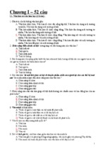
In Fig. 1.12, another type of sensing microgripper is shown [12]. The actuator design
is based on three doped silicon beams connected by an end bar. The two inner beams
are electrically connected in parallel. When a voltage is applied between the outer
beams and the two connected inner beams, the current in the outer beam is twice the
current in the inner one. Therefore, the outer beam functions as the hot arm of an
electrothermal actuator. The displacement of the actuator is detected by monitoring
the resistance change of the two inner beams. The microgripper displacement is due to
the thermal expansion of silicon, a material with a low CTE. Therefore, the
microgripper displacement and sensor output is quite small.
Figure 1.12: Piezoresistive feedback microgripper: (a) optical image of the device; (b) a typical
Wheatstone bridge resistor configuration; (c) gripper made with two actuators in the three-beam
configuration, which are connected as a Wheatstone bridge circuit; and (d) gripper configuration with
three actuators consisting of the three-beam structure connected to avoid thermal stress influencing
the force detection [12].
16
Figure 1.13: Solid model of the electrostatic microgripper with integrated force sensor: one comb
capacitor is used as actuator and the other one is the sensing part [7].
An electrostatic microgripper with an integrated capacitive force sensor is shown in
[18] (see Fig. 1.13). It consists of a lateral comb drive for actuating the gripper and
another for force sensing. This device is capable of motion of up to 100 µm with force
sensitivity of 4.41 kV/m, and corresponding 70 nN force-sensing resolution. However,
this device requires high drive voltage, large dimensions and a complicated electronic
circuit.
Another sensing microgripper is shown in [17] (see Fig. 1.14). This device combines a
CMOS photo-detector and a polymeric electrothermal actuator based on the hot-andcold-arm design [19]. By using an external light source, this device is capable of
detecting the object present between two gripper jaws. However, this method does not
offer the possibility of monitoring the contact force between the manipulator tip and
the object grasped.
Figure 1.14: (a) Schematic of a simple 2 x 2 CMOS micro-machined gripper array with on-chip optical
detection and (b) gripper with a polystyrene bead [17].
17
Chapter 2 Sensing Microgripper
2.1 Introduction
For many of the application areas of micromanipulators force control is highly
desirable as dexterity, accuracy and speed are considerably improved by a feedback
system [16]. A microgripper with a built-in force sensor is suitable for holding objects
firmly, whilst avoiding any squeezing of delicate objects.
As discussed in chapter 1, several designs of microgrippers with force feedback have
been demonstrated in recent years [5, 7, 9, 12, 18]. However, these devices suffer
from some limitations: either they are large in size and thus not suitable for
micromanipulation; or require a fabrication process that is not CMOS-compatible
and/or need a complicated electronic circuit. In this chapter a novel sensing
microgripper based on silicon-polymer electrothermal actuators and a piezoresistive
force-sensing cantilever beam is introduced.
2.2 Force-sensing cantilever
A novel two-dimensional nano-Newton force-sensing piezoresistive cantilever is
presented with providing nano-Newton sensitivity, a wide force measurement range,
and the possibility of being combined with handling tools. Instead of using sidewall
implantation, two separate sensing piezoresistors are located on each sides of the
cantilever. By using two switches to change the Wheatstone bridge configuration, the
piezoresistive cantilever is capable of detecting both the lateral and vertical bending
independently. Consequently this force-sensing cantilever can detect the applied
forces in both parallel and perpendicular direction to the wafer surface. The cantilever
is made on regular silicon wafers with a fabrication process compatible with CMOS
technology.
In Fig. 2.1 a schematic drawing of the two-dimensional piezoresistive force sensing
cantilever is shown. The four piezoresistors are located on the surface of the structure.
The piezoresistors are aligned along the [110] direction of the (001) crystal plane of a
silicon wafer. The resistor pairs located on the cantilever are stress-sensing resistors
(the resistance changes when the cantilever is deflected). Two other resistors are
outside the cantilever. They are not subjected to stress and therefore they are used for
common-mode signal compensation in a Wheatstone bridge arrangement [4].
18
Figure 2.1: Schematic drawing of the two-dimensional piezoresistive force-sensing cantilever with
geometric symbols and orientations used [4].
When a force F is applied to the tip of the cantilever the cantilever bends. On the yz plane, perpendicular to the longitudinal x -axis of the cantilever, the applied force F
can be determined as two components: Fz is the lateral and Fy is the vertical
component (see Fig. 2.1). By monitoring Fz and Fy we can obtain both amplitude and
direction of the applied force [4].
2.3 Silicon-polymer electrothermal microgripper
A novel silicon-polymer laterally stacked electrothermal in-plane microactuator is
proposed. The device is composed of three materials: a metal heating layer, a silicon
frame with high heat conductivity and a polymer with a high thermal expansion
coefficient (CTE). During actuation, heat is efficiently transferred from the heater to
the polymer thanks to the high thermal conduction of the deep silicon structures which
have a large interface with the surrounding polymer. Moreover, the polymer layer is
constrained between two silicon plates. The thermal expansion of the constrained
polymer is three times larger than the no constraint one.
Fig. 2.2 shows the sketch of a silicon polymer block. It consists of laterally stacked
silicon-polymer segments. Each segment is formed by a rectangular plate of polymer
which is bonded between two silicon plates. The metal heater is on the top of the
silicon. Instead of transferring heat directly from the heater to the polymer as in the
conventional developed designs [19], the efficient distribution of the heat to the
polymer occurs through the large interface areas between the silicon plate and the
polymer. Polymer layers are bonded between two silicon plates which constrain the
expansion of the polymer layer in the direction parallel to the plate surfaces.
Therefore, the thermal expansion of the polymer plate is enhanced in the
perpendicular direction.
Sketches of the microgripper based on a silicon comb structure are shown in Fig.
2.3(a). The microgripper is designed for normal open operation mode. Each actuator
19
has a silicon comb finger structure with the aluminum heater on the top. A thin layer
of silicon nitride is used as the electrical isolation between aluminum structure and
silicon substrate. The gaps between comb fingers are filled with SU8 polymer. Each
actuator consists of 41 silicon fingers and SU8 layers in between. The polymer comb
fingers are 3 µm wide, 75 µm long and 30 µm thick. The ratio between the width of
the polymer layer and the dimensions of its bonded surface with silicon rigid plate are
25 and 10, respectively. These ratio values satisfy the prerequisite for the maximum
constraint effect.
When the heater is activated, the generated heat is efficiently transferred to the
surrounding polymer though the deep silicon comb finger structures which have a
large interface area with the polymer layer. The polymer layers expand along the
lateral direction causing bending displacement of the actuator arm [4].
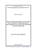
Figure 2.2: (a) Scheme of the silicon polymer laterally stacked segments; (b) Side cross-section of a
single segment depicting the constrained polymer between two rigid silicon plates [4].
Figure 2.3: a) Sketch of the silicon-polymer electrothermal microgripper based on the silicon comb
structure, b) top and cross-section view of the silicon-polymer electrothermal microgripper based on
the silicon comb structure [4].
20
2.4 Sensing microgripper
The sensing microgripper is based on the combination of a silicon-polymer
electrothermal microactuator and a piezoresistive lateral force-sensing cantilever
beam. A schematic drawing is shown in Fig. 2.4. When the electrothermal actuator is
activated, the microgripper’s arm and also the sensing cantilever are bent. This causes
a difference in the longitudinal stress on the opposite sides of the cantilever. This
changes the resistance value of the sensing piezoresistors on the cantilever changes.
The displacement of the microgripper jaws can be monitored by the output voltage of
the Wheatstone bridge of the piezoresistive sensing cantilever beam. The contact force
between the microgripper jaws and clamped object is then determines based on
displacement and stiffness of microgripper arm [4].
Figure 2.4: a) Schematic drawing of the sensing microgripper, b) Top and cross-section view of a
sensing microgripper arm with geometry symbols and parameters. The Wheatstone bridge
configuration is also shown [4].
The sensing microgripper is designed for normal open operating mode, using the
silicon-polymer electrothermal microgripper based on the silicon comb structure. This
configuration is more rigid than the one based on the silicon serpentine and therefore
preferred.
The force sensor is designed based on the lateral force-sensing piezoresistive
cantilever beam as presented in 2.2 paragraphs. The four piezoresistors are located on
the cantilever beam structure and connected to create a Wheatstone bridge. The
piezoresistors are aligned along the [110] direction in the (001) crystal plane of the
silicon wafer. The resistor pairs located on the cantilever are the stress sensing
resistors. When the electrothermal actuator is activated, the cantilever beam is bent
parallel to the wafer surface. Therefore, the differential change of resistance occurs on
the two resistors RS1 and RS2.
21
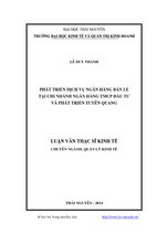
Figure 2.5: SEM picture of (a) the sensing microgripper and close-ups of (b) the piezo-resistors; (c)
the jaws, and (d) a section of the thermal actuator [4].
- Xem thêm -