GRADUATE UNIVERSITY OF SCIENCE AND TECHNOLOGY
INSITUTE FOR TROPICAL TECHNOLOGY
SUMMARY OF PhD THESIS IN CHEMISTRY
ELECTRODEPOSITION OF
HYDROXYAPATITE/MODIFY CARBON NAOTUBES ON
ALLOYS TO APPLY FOR BONE IMPLANTS
Specialization: Theoretical and Physical chemistry
Code: 9 44 01 19
Hanoi 2019
1
The dissertation completed at:
Academic supervisors:
1.
2.
Reviewer 1:
Reviewer 2:
Reviewer 3:
2
INTRODUCTION
Reason to choose the topic
Hydroxyapatite (Ca10(PO4)6(OH)2, HAp) is the main inorganic component in human
bones and teeth, has high biocompatibility. HAp is applied in medicine with different forms:
powder, ceramic, composite and coating. Synthetic HAp has the same composition in natural
bone and has good biocompatibility. However, pure HAp coating has a relatively high
solubility in physiological environment and poor mechanical properties leading to faster
degradation of the material and reducing the fixed ability between the implant material and
the host tissue. Some reports show that the doping of carbon nanotubes to create HApCNTcomposite significantly improves the mechanical properties of materials such as
corrosion resistance and mechanical strength. The thesis: "Electrodeposition of
hydroxyapatite/modify carbon nanotubes coating on alloys to apply for bone implants"
shows investigation to synthesize HAp-CNTsbt coating on 316LSS and Ti6Al4V.
Objectives of the thesis:
- Selecting of suitable conditions to synthesize HAp-CNTsbt nanocomposite coating on
316LSS and Ti6Al4V.
- HAp-CNTbt coating has biocompatibility and protection ability for the substrate in
comparison with HAp coating.
• Main content of the thesis:
1. Study on effect of the scanning potential range, scanning rate, number of scans, CNTbt
amount, and synthesis temperature on the characteristics of HAp-CNTbt coating. Selecting of
suitable conditions for synthesie HAp-CNTbt/316LSS and HAp-CNTbt/ Ti6Al4V materials.
2. Determination of roughness, elastic modulus and hardness of 316LSS, Ti6Al4V,
HAp/316LSS,
HAp/Ti6Al4V,
HAp-CNTbt/316LSS,
and
HAp-CNTbt/Ti6Al4V.
Determination of dissolutione of HAp and HAp-CNTbt coating in 0.9% NaCl solution.
3. Research on biocompatibility and electrochemical behavior of 316LSS, Ti6Al4V,
HAp/316LSS, HAp/Ti6Al4V, HAp-CNTbt/316LSS, and HAp-CNTbt/ Ti6Al4V in SBF
solution.
CHAPTER 1: OVERVIEW
1.1. Overview for Hydroxyapatite
1.1.1. Properties of Hydroxyapatite
1.1.1.1. Structural properties
Hydroxyapatite (HAp) exists in two structural forms: hexagonal (hexagonal) and monoclinic
(monoclinic). Hexagonal HAp is usually formed during synthesis at temperatures between
25 and 100 °C. The monoclinic form is mainly created by heating the hexagonal HAp at
850 °C in air, then cooling to room temperature.
1.1.1.2. Physical properties
HAp exists in crystal with some parameters: molar mass of 1004.60 g, density of 3.08 g/cm3,
hardness in the Mohs scale by 5, melting temperature of 1760oC, and boiling temperature
2850 oC. The dissolution of HAp in the water is 0.7 g/L. HAp crystals usually have rodshape, needle-shape, scale-shape, fibrous-shape, spherical-shape, and cylindrical-shape.
3
1.1.1.3. Chemical properties
• HAp reacts with acids to form calcium salts and water.
• HAp is relatively thermally stable, which is decomposed slowly at temperature range of
800°C ÷ 1200°C, to form oxy-hydroxyapatite.
• At bigger temperatures (> 1200°C), HAp is broken down to β - Ca3(PO4)2 (β - TCP) and
Ca4P2O9 or CaO.
1.1.1.4. Biological properties
HAp has a high biological compatibility, non-toxic, non-allergenic to the human body
and has high antiseptic properties.
1.1.2. Methods of synthesis of hydroxyapatite coating
a. Physical method
The physical method is the method of creating HAp coating from ions or phase transition.
These methods have the advantage of being able to easily fabricate HAp coating with a
thickness of µm. Several physical methods are used: plasma, vacuum evaporation and
magnetron sputtering [2, 37].
b. Electrochemical method
Electrochemical method has many advantages in making thin coating on metal or alloys for
biomedical applications. Electrochemical technique is a simple technique that allows the
synthesis of HAp coating at low temperatures. The obtained HAp coating is of high purity,
good adhesion to the substrate and we can control the coating thickness. HAp coating with
thickness of nm size are synthesized on different substrates by electrochemical method such
as: Electrophoresis method, Anode method, Cathode deposition method.
1.1.3. Application of HAp
1.1.3.1. Application of HAp powder
HAp powder with nano size is mainly used for medicine and calcium supplements. In
addition, HAp is used as a slow-release nitrogen fertilizer for plants.
1.1.3.2. Application of HAp porous ceramic
Porous ceramic of HAp is used in making dentures and repairing dental defects,
making artificial eyes, making bone graft details and repairing bone defects.
1.2.3.3. Application of HAp composite
HAp is combined with biodegradable polymers such as polylactic acid, polyacrylic
acid, chitosan ... to create replacement materials for bone.
1.2.3.4. Application of HAp coating
HAp coating on the suface of biomedical materials is applied in dentistry, orthopedic bone.
1.2. Overview of carbon nano tubes materials
1.2.1. Properties
1.2.1.1. Structure of CNT: CNT are graphene sheets which are rolled up to form a hollow
cylinder. Depending on rolling direction, CNT materials are divided into armchair, zigzag
and chiral types.
1.2.1.2. Physical properties
1.2.1.2.1. Mechanical properties
CNT have a good mechanical property, durable and low density. So, they are used as
reinforcement for rubber, polymer, and metals to improve durability and abrasion resistance
for materials.
1.2.1.2.2. Electrical properties
4
The electrical properties of CNT depend strongly on its structure. The electrical
conductivity of CNTs is corresponding to semiconductor or metal.
1.2.1.2.3. Thermal properties
CNTs are good thermal conductors, at room temperature the thermal conductivity of
CNTs is about 3,103 W / m.K.
1.2.1.2.4. Emisivity properties
The electronic emissivity ability of CNT is very high.
1.2.1.2. Chemical properties
About chemical property, CNT are relatively inert. To improve the chemical activity
of CNT, CNT usually are modified to create surface defects.
1.2.2. Application of CNT materials
CNT are used in energy storage, electronic, reinforcing materials and medical
applications (CNT are used in biosensors, drug delivery, and nanotechnology application for
bone implants).
1.2.3. Modification of CNT
- CNT is modified by oxidizing agents, a combined reaction, and substitution reaction
1.3. Composite of hydroxyapatite/carbon nano tubes (HAp-CNTbt)
HAp-CNTbt composite is synthesized by many different methods. The research results
show that the presence of CNT improved the mechanical properties for HAp by the increase
of elastic modulus and the hardness.
1.4. In vitro and In vivo tests
The results of biocompatibility of HAp-CNT in Hanks solution or simulated body
fluid solution (SBF) show that the material has good biocompatibility with the development
of new apatite crystals. The results of in vitro test by cells (osteoblast) showed that there is a
good growth.
1.5. Investigation in Vietnam
In Vietnam, there are some reports about HAp powder, coating, ceramic and
composite. Since 2011, Dinh Thi Mai Thanh et al. (Institute of Tropical Technology)
investigated on HAp powder, PLA/HAp composite and HAp coating on the surface of
304LSS, 316LSS, TiN/316LSS, Ti6Al4V and CoNiCrMo.
We realize that, investigation of HAp-CNT coating is quite new in Vietnam. This study
aims are selection of suitable conditions to synthesize HAp-CNTcoating on the surface of
316LSS, Ti6Al4V substrates by scanning potential method.
Chapter 2. CONDITION AND EXPERIMENTAL METHOD
2.1. Chemicals and experimental conditions
2.1.1. Chemicals
- Ca(NO3)2.4H2O, NH4H 2PO4, NaNO3, NaCl, NaHCO3, KCl, Na2HPO4.2H2O,
MgCl2.6H2O, CaCl2, KH2PO4, MgSO4.7H2O, C6H 12O 6, NH4OH, HCl, HNO3 67 % and
H2SO4 98 %. CNTs: 90 % of pure, d = 20 – 100 nm, L = 1 - 10 µm is produced at Insitute of
Material Science.
- The materials of 316LSS (100×10×2 mm) and Ti6Al4V (12×10×2 mm) were
purchased from Gloria Technology Material Company (Taipei, Taiwan) with element
components are listed in Table 2.1 and 2.2.
Table 2.1. The element component of 316LSS
Element
Al
Mn
Si
Cr
Ni
Mo
P
Fe
Component (%) 0.3
0.22
0.56 17.98 9.34 2.15 0.045 69.405
5
Table 2.2. The element component of Ti6Al4V
Element
Ti
Al
V
C
Fe
Component (%)
89,63
6,04
4,11
0,05
0,17
2.1.2. Electrodeposition of HAp-CNTon 316LSS or Ti6Al4V
* Preparation of substrate: 316LSS and Ti6Al4V were polished by SiC paper of 600, 800
and 1200 (Japan). After that, they were clearned and dried. The working area was limited of
1 cm2 by epoxy.
* Modification of CNTs:
4 g CNTs were put in a container containing 200 ml of H2SO4 and HNO3 (3:1) acids
with 1 h of ultrasonic. Then, the mixtre was heated at 110oC for 1 h using a concender.
CNTs were obtained using centrifuge to neutral pH and dried at 80oC for 48 h.
Then, 0.05 g CNT or CNTbt was dispersed into two tubes containing 50 mL of
Ca(NO3)2 3x10⁻² M, NH4H2PO4 1.8x10⁻² M, NaNO 3 0.15 M solution (the solution is used to
synthesize HAp coating) with pH o = 4.3 and ultrasound for 20 minutes. These two tubes
were left on the shelf for 7 days to observe the dispersion of CNT or CNTbt. The pH of the
two solutions containing CNT and CNTbt were also measured.
* The different conditions to synthesize HAp and HAp-CNTsbt coating.
HAp and HAp-CNTsbt coating were synthesized by scanning potential method. The
electrolyte solution contains 3x10⁻² M Ca(NO3)2, 1.8x10⁻² M, NH4H 2PO4, and 0.15 M
NaNO3. The coatings were synthesized in a cell of three electrodes: the working electrode is
316LSS or Ti6Al4V, The counter electrode of Platinium; and reference electrode of
Ag/AgCl (SCE). The factors investigated:
Table 2.3. The conditions to synthesize HAp-CNTbt/316LSS and HAp-CNTbt/Ti6Al4V
Survey factor
Fixed installation factor
1
- Scanning potential: 0 ÷ -1.4 V;
Scanning rate of 5 mV/s, 5 scans, 45 oC
0 ÷ -1.5 V; 0 ÷ -1.6 V; 0 ÷ -1.65 V; 0 ÷ - and CNTbt 0.5 g/L.
1.7 V; 0 ÷ -1.8 V; 0 ÷ -1.9 V; 0 ÷ -2.0 V
and 0 ÷ -2.1 V
2
- Concentration of CNTbt: 0.25; 0.5; 0.75 0 ÷ -1.65 V (for 316LSS);
and 1 g/L
0 ÷ -2.0 V (for Ti6Al4V); 5 mV/s; 5
scans, 45 oC.
3
- Synthesis temperature: 30, 45, 60 oC
0 ÷ -1.65 V (for 316LSS);
0 ÷ -2.0 V (for Ti6Al4V); 5 mV/s; 5
scans, CNTbt 0.5 g/L
4
- Scanning rate: 2, 3, 4, 5, 6 and 7 mV/s. 0 ÷ -1.65 V (for 316LSS);
0 ÷ -2.0 V (for Ti6Al4V); 5 scans,
45 oC, CNTbt 0.5 g/L
5
- Scanning times: 3, 4, 5 and 6 scans
0 ÷ -1.65 V (for 316LSS);
0 ÷ -2.0 V (for Ti6Al4V); 5 mV/s;
45 oC, CNTbt 0.5 g/L
2.1.3. In vitro test in SBF solution
1 L of SBF solution containing: NaCl (8 g/L); NaHCO3 (0.35 g/L); KCl (0.4 g/L);
Na2HPO4.2H2O (0.48 g/L); MgCl2.6H 2O (0.1 g/L); CaCl2 (0.18 g/L); KH 2PO4 (0.06 g/L);
MgSO4.7H2O (0.1 g/L) and glucozo (1 g/L). The initial pH is 7.3. Electrochemical behavior
6
of the materials in 50 ml of SBF solution was carried in the cell of three electrodes, at 37 ± 1
o
C.
2.2. Methods
2.2.1. Electrochemical methods
Dynamic scanning method, Method of measuring open-circuit potential and
Electrochemical Impedance Spectroscopy.
2.2.2. Analysis methods
Characteristics of these materials were determined by IR, SEM, EDX, TEM, XRD,
AFM, TGA, measuring adhesion, determination of coating mass and thickness,
determination of solubility of HAp and HAp-CNTsbt coating, and the methods to measure
the mechanical properties of HAp and HAp-CNTsbt materials.
CHƯƠNG 3: RESULTS AND DISCUSSTION
3.1. Modification of CNTs
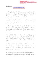
The IR spectrum of CNTs: C=C at 1630 cm-1, was overlap with the vibracation of –OH
group in the water, the vibracation of –OH at 3400 cm-1. The IR spectrum of CNTsbt: the
peak of –OH in water at 3400 cm-1. 2 peaks at 1720 cm-1 and 1385 cm-1 characteristic of
C=O and C-OH. The results confirm that CNTs was modified successfully.
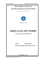
Figure 3.2 shows that after 7 days soaked in water, CNTs was clumped by Van der
Waals forces. CNTsbt dispersed well into water due to the presence of –COOH groups on the
surface of CNTsbt, which reduces interaction of Van der Waals forces. SEM images show
that CNTs and CNTsbt have tubular structures.
§é truyÒn qua(%)
CNTsbt
1720
1385
CNTs
4000
1630
3500
3000
2500
2000
1500
1000
500
-1
Sè sãng(cm )
Figure 3.1-3.3. IR spectra, dispersion and SEM images of CNTs and CNTsbt
Bảng 3.3. Thành phần các nguyên tố của
CNT và CNTbt
Nguyên
Nguyên tố
Nguyên tố
tố
m% a% m% a%
C
85.43 90.84 81.42 85.37
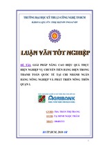
Figure 3.4. EDX spectra of CNTs and CNTsbt
O
EDX spectrum of CNTs (Figure 3.4) shows Al
characteristic peaks of C, O, Fe, Al and Pt Fe
(Table 3.1). EDX spectrum of CNTsbt shows Total
9.85
0.89
3.83
100
9.85
0.89
3.83
100
7.86
0.42
0.88
100
7.26
100
characteristic peaks of C and O. The
modification process of CNTs removed heavy
metal catalysis.
3.2. Synthesis and characterization of HAp-CNTsbt composite
3.2.1. Effect of snanning potential range
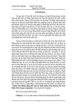
Cathode polarization curves of 316LSS and Ti6Al4V (Fig. 3.5): 0 ÷ -0,7 V/SCE, i≈ 0
because no reaction occurs. -0,7 ÷ -1,2 V/SCE, i increases slightly corresponding to
reduction of H+, O2 in water.
7
Potential <-1.2 V /SCE, i increases
strongly by the reduction of H2PO4- and
H2O ((3.3), (3.4), (3.5) and (3.6)). HApCNTsbt was formed by reaction (3.7), (3.8)
(3.9). HAp-CNTsbt coating are formed by
the formation of hydrogen bonds between
-COOH group of CNTsbt and -OH group
Fig. 3.5. Cathode
Fig. 3.6. Hydrobonding of HAp.
polarization curves
between HAp-CNTsbt
+
H 2 PO 3 2 OH (3.5)
(3.1) H 2 PO 4 H 2 O 2 e
2H + 2e H2
2 H 2 O 2e
H 2 2OH
2 H 2 O 2e
H 2 2OH
(3.2)
(3.6)
2
2
2 H 2 PO 4 2 e
2 HPO 4 H 2
H 2PO 4 OH
HPO 4 H 2 O
(3.3)
(3.7)
3
2
3
H 2 PO 4 2e
PO 4 H 2
HPO 4 OH
PO 4 H 2 O
(3.4)
(3.8)
2
3
10 Ca 6 PO 4 2OH
Ca 10 ( PO 4 ) 6 ( OH ) 2
(3.9)
2
For 316LSS, at 0 ÷ -1.4 or -1.5 V/SCE, i was small (-0.6 and -0.9 mA/cm ), there is not
the formation of HAp-CNTsbt coating on the substrate. At larger potential range, the coating
mass increased and reached a maximum at 0 ÷ -1.9 V/SCE. The mass and thickness
decreases when it synthesized at 0 ÷ -2 V/SCE. At 0 ÷ -1.6 and 0 ÷ -1.65 V/SCE, the
obtained materials had the same adhesion. The adhesion decreased about twice for the
materials synthesized at 0 ÷ -2.0 V/SCE. Therefore, 0 ÷ -1.65 V/SCE was chosen to
synthesize HAp-CNTsbt/316LSS coating. For Ti6Al4V, at 0 ÷ -1.4 V/SCE or 0 ÷ -1.5
V/SCE, i was -2.4 and -3.5 mA/cm2, the coating was nearly formed. The coating mass
increased and reached at 0 ÷ -2.1 V/SCE. The adhesion between the coating and substrate
decreased at large potential range. Therefore, 0 ÷ -2.0 V/SCE was chosen to synthesize
HAp-CNTsbt/Ti6Al4V. The results can be explained as following: when the potential range
was extended, icathode increased → ion OH- and PO43- were formed → diffuse and form HAp
in solution. On the other hand, the large cathode potential was favorable for the electrolysis
of water → H 2 was formed on the surface of 316LSS and Ti6Al4V leading to porous HApCNTsbt coating was obtained and the adhesion decreased.
Table 3.2. Mass, thickness and adhesion strength of HAp-CNTsbt at different potential range
5
0
0.1
-5
0.0
-0.1
-10
-0.2
2
i (mA/cm )
-0.3
-15
-0.4
-0.5
-0.6
-20
-0.7
-0.8
-25
-0.9
-1.2
-1.0
-0.8
-0.6
-0.4
-0.2
0.0
-30
TKG316L
Ti6Al4V
-35
-40
-2.2 -2.0 -1.8 -1.6 -1.4 -1.2 -1.0 -0.8 -0.6 -0.4 -0.2 0.0
E (V/SCE)
Potential range
(V/SCE)
0 ÷ -1.4
0 ÷ -1.5
0 ÷ -1.6
0 ÷ -1.65
0 ÷ -1.7
0 ÷ -1.8
0 ÷ -1.9
0 ÷ -2.0
0 ÷ -2.1
Mass (mg/cm2)
316LSS
1.79
2.10
2.29
2.78
3.16
2.26
-
Ti6Al4V
1.320
1.43
1.64
1.88
2.08
2.33
Thickness (µm)
316LSS
5.90
6.90
7.80
9.00
10.10
7.30
-
Ti6Al4V
4.00
4.30
4.90
5.70
6.30
7.00
Adhesion strength (MPa)
316LSS
13.37
13.20
10.08
9.40
9.00
6.70
-
Ti6Al4V
12.20
11.90
11.60
11.00
10.40
7.40
The adhesion between HAp and 316LSS is explained as following: Ca2+ ion in the
solution interacted with oxide layer of 316LSS, so they accumulate on the surface and
diffused into passive membrane of 316LSS. When the amount of accumulated Ca2+ was
large, the surface of 316LSS gradually charged positively and combined with negatively
charged HPO42-, PO43- and OH- ions to form HAp on the surface of 316LSS. On the other
8
hand, the diffusion of Ca2+ on the passive membrane of the substrate leads to the strong
formation of surface interaction between 316LSS and HAp, improving the adhesion of HAp
coating to the substrate [98-101]:
FeOOH + Ca2+ → {FeOO -…Ca2+} + H+
(3.11)
2+
22+
2{FeOO …Ca } + HPO 4 → { FeOO …Ca …HPO4 }
(3.12)
{FeOO -…Ca2+} + PO43- + OH - → { FeOO-…Ca2+…PO43-…OH -}
(3.13)
For Ti6Al4V substrate, the mechanism of the adhesion between HAp coating and
substrate was explained: There is oxide layer of TiO2 on the surface of Ti6Al4V. In the
synthesis process, some reactions occured leading to the presence of corrosive products [98101]:
{TiO 2} + 2H2O → Ti(OH)4
(3.14)
+
−
{TiO2} + 2H2O → [Ti(OH)3] + OH
(3.15)
−
+
{TiO2} + 2H2O → [TiO2OH ] + H 3O
(3.16)
2+
Ca ions into the solution diffused into the surface of titanium oxide.
{Ti–OH} + Ca2+ → {TiO−···Ca2+} + H +
(3.17)
−
2+
2−
−
2+
2−
{TiO ···Ca } + HPO4 → {TiO ···Ca ···HPO4 } + OH
(3.18)
−
2+
3−
−
−
2+
3−
{TiO ···Ca } + PO4 + OH → {TiO ···Ca ···PO4 ···OH }
(3.19)
FTIR spectra showed that potential range does not affect to the characteristic peaks of
HAp and CNTs: PO 43-: 1040; 600 and 560 cm-1. The shilfting of C-OH(CNTsbt) from 1385
cm-1 to 1380 cm-1 was explained by reaction between Ca2+ of HAp and COO- of CNTsbt.
Fig. 3.7-8. IR spectra of HAp-CNTsbt/316LSS
and HAp-CNTsbt/Ti6Al4V at different potential
Fig. 3.9-10. XRD of HAp-CNTsbt/316LSS and
HAp-CNTsbt/Ti6Al4V at different potential
XRD paterns presented that HAp-CNTsbt/316LSS materials had characteristic peaks of
HAp and CNTs. Peak at 2θ ~ 32o of HAp. Peak at 25.88o of HAp was not observed because
of overlap with peak at 26o of CNTs. XRD patern of the coating synthesized at 0 ÷ -1.6
V/SCE appeared characteristic peaks of DCPD (CaHPO4.2H2O. DCPD) at 2θ ~ 29.2o; 43o;
51o because, formed OH- was not enough to completely transfer HPO42- to PO43- at small
potential range. For Ti6Al4V, XRD paterns of HAp-CNTsbt coating synthesized at 0 ÷ -1.6
và 0 ÷ -1.7 V/SCE was observed phase of DCPD. At larger potential range, the obtained
coating composed phases of HAp and CNTs.
SEM images showed that HAp-CNTsbt/316LSS had scales-shapes when they were
synthesized at 0 ÷ -1.6 V/SCE; 0 ÷ - 1.65 V/SCE and has plate shapes with large size when
they were synthesized at a wide range. SEM images of HAp-CNTsbt/Ti6Al4V had scalesshapes and uniform when they were synthesized in small potential ranges. At 0 ÷ -2.1 V /
SCE, the coating was porous. TEM images were observed CNTsbt in the coating (Fig. 3.13).
9
Fig. 3.11. SEM images of HAp-CNTsbt/316LSS
synthesized at different potential range
Fig. 3.12. SEM images of HAp-CNTsbt/Ti6Al4V
synthesized at different potential range
3.2.2. Effect of temperature
Cathodic polarization curves of 316LSS and Ti6Al4V at different temperature were the
same (Fig. 3.20 and 3.21). The temperature increased leading to the increase of reaction rate
and current density. The temperature increased leading to the mass, thickness increased but
the adhesion strength decreased (Table 3.5). Therefore, the temperature of 45 oC was chosen.
1
0
5
0
-5
-10
-4
-5
-6
-7
-8
-9
-10
-11
i (mA/cm2)
2
i (mA/cm )
-1
-2
-3
o
30 C
o
37 C
o
45 C
o
50 C
o
60 C
-12
-13
-1.8
-1.6
-1.4
-1.2
-1.0
-0.8
-0.6
E (V/SCE)
-0.4
-0.2
0.0
-15
-20
-25
-30
-35
0.1
0.0
-0.1
-0.2
-0.3
-0.4
-0.5
-0.6
-0.7
-0.8
o
30 C
o
37 C
o
45 C
o
50 C
o
60 C
-1.2 -1.0 -0.8 -0.6 -0.4 -0.2 0.0
0.2
-40
-2.2 -2.0 -1.8 -1.6 -1.4 -1.2 -1.0 -0.8 -0.6 -0.4 -0.2 0.0 0.2
E (V/SCE)
Fig. 3.20-21. Cathodic polarization curves of
Fig. 3.22-23. XRD paterns of HAp-CNTsbt on
316LSS and Ti6Al4V at different temperature
316LSS and Ti6Al4V at different temperature
Table 3.5. Mass, thickness and adhesion strength of HAp-CNTsbt followed temperature
Mass (mg/cm2)
Thickness (µm)
Adhesion strength (MPa)
Temperature
(oC)
316LSS Ti6Al4V 316LSS
Ti6Al4V
316LSS
Ti6Al4V
30
1.16
1.18
3.80
3.40
14.03
12.00
37
1.61
1.54
5.30
5.10
13.08
11.10
45
2.10
2.08
6.90
6.30
13.2
10.40
50
3.28
3.13
11.98
11.86
8.45
7.22
60
3.73
3.81
12.20
11.40
6.05
6.00
XRD paterns showed that the temperature đo not affect to phase component of the
coating (Fig. 3.22 and 3.23). HAp-CNTsbt coating composed phases of HAp and CNTs.
SEM images of HAp-CNTsbt had scales shapes when they were synthesized at 30 oC and 45
o
C. At 60 oC, the obtained coating had leaves shape with big size.
10
Fig. 3.24. SEM images of
HAp-CNTsbt/316LSS at
different temperature
Fig. 3.25. SEM images
of HAp-CNTsbt/Ti6Al4V
at different temperature
3.2.3. Effect of CNTsbt concentration
The amount of CNTsbt in the electrolyte increased, the cathode current density
increased. The coating mass and thickness decreased with the presence of CNTsbt due to
voluminous molecular structure of CNTs which prevented the formation of HAp in the
substrate. However, the presence of CNTsbt in the coating improved the adhesion strength
between the coating and substrate. From table 3.4. 0.5 g/L of CNTsbt was chosen for
further investigation.
-2
-10
-3
-15
2
i (mA/cm )
0
-5
2
i (mA/cm )
5
0
-1
-4
-5
0g CNTs
0.25g CNTs
0.5g CNTs
0.75g CNTs
1g CNTs
-6
-7
-8
-9
-1.8 -1.6 -1.4 -1.2 -1.0 -0.8 -0.6
E (V/SCE)
-0.4 -0.2
0.0
0.2
-20
-25
0 g/L CNTs
0,25g/L CNTs
0,5 g/L CNTs
0,75 g/L CNTs
1 g/L CNTs
-30
-35
-40
-45
-2.2 -2.0 -1.8 -1.6 -1.4 -1.2 -1.0 -0.8 -0.6 -0.4 -0.2 0.0
E (V/SCE)
Fig. 3.13. TEM images of HAp-CNTsbt on
Fig. 3.14-15. Cathodic Polarization curves of 316LAA and
316LSS (A) and Ti6Al4V (B)
Ti6Al4V in electrolyte with the different CNTsbt amount
Table 3.4. The variation of mass, thickness and adhesion strength of HAp-CNTsbt synthesized at different
amount of CNTsbt
Thickness (µm)
Mass (mg/cm2)
Adhesion strength (MPa)
Amount of
ISO 4288-1998
CNTsbt (g/L)
316LSS Ti6Al4V
316LSS
Ti6Al4V
316LSS
Ti6Al4V
0,00
2.63
2.81
8.66
8.90
5.35
4.50
0.25
2.13
2.19
6.920
6.80
10.24
9.20
0.50
2.10
2.08
6.90
6.30
13.20
10.40
0.75
1.96
1.56
6.70
4.70
11.19
7.10
1,00
1.74
1.34
5.70
4.10
9.35
6.20
IR spectra showed characteristic peaks for vibracation of groups in HAp and CNTsbt
(3.2.1 section). From TG/DTG diagram we can be calculated amount of CNTsbt in
HAp-CNTsbt/316LSS and HAp-CNTsbt/Ti6Al4V was 5, 7, 7 and 6 % corresponding to
CNTbt concentration of 0.25; 0.5; 0.75 and 1 g/L.
Fig. 3.16-17. IR spectra of HAp-CNTsbt
with different amount of CNTsbt
Fig. 3.24. TG/DTG diagram 0f HAp/316LSS (a) and
HAp/Ti6Al4V (b)
11
Fig. 3.25. TG/DTG diagram of Hap-CNTsbt /316LSS synthesized at 0 ÷ -1,65 V; 5 mV/s, 5 scans; 45 oC with
CNTbt : 0,25 g/L (a); 0,5 g/L (b); 0,75 g/L (c) and 1 g/L (d)
Fig. 3.26. TG/DTG diagram of HAp-CNTbt/Ti6Al4V synthesized at 0 ÷ -2 V; 5 mV/s, 5 scans; 45 oC with
CNTbt : 0,25 g/L (a); 0,5 g/L (b); 0,75 g/L (c) and 1 g/L (d)
3.2.4. Effect of number scans
The number of scans increased, mass and thickness increased but the adhesion strength
decreased. Hap-CNTsbt coating synthesized with 3 scans had the adhesion of 14.5 MPa
which was similar with adhesion of substrate and glue. When the number of scans increased
(4 or 5 scans). Hap-CNTsbt coating was uniform. smooth. thick and completely covers for
the substrate. Continue to increase the scans to 6 times. the adhesion between the coating
and substrate was strongly reduced. Therefore, 5 scans were selected to synthesize
HAp-CNTsbt/316LSS and HAp-CNTsbt/Ti6Al4V coatings.
Table 3.6. Mass. thickness and adhesion strength of HAp-CNTsbt followed number scans
Thickness (µm)
Adhesion
Number
Mass (mg/cm2)
ISO 4288-1998
(MPa)
scans
316LSS
Ti6Al4V
316LSS
Ti6Al4V 316LSS Ti6Al4V
3
1.03
0.92
3.40
3.00
14.50
12.60
4
1.72
1.92
5.60
6.10
13.34
10.70
5
2.10
2.08
6.90
6.30
13.20
10.40
6
2.69
2.32
8.80
7.50
8.60
7.00
XRD paterns showed that number scans does not affect to phase component of the
nanocomposite. HAp-CNTsbt coating had crystal structure and composed the phase of HAp
and CNTs (Fig. 3.27 and 3.28).
Cêng ®é nhiÔu x¹ (%)
1
1, 2
1.HAp; 2.CNTs
1
1
1
1
6 lÇn quÐt
5 lÇn quÐt
1
Cêng ®é nhiÔu x¹ (%)
1, 2
1
1
6 lÇn quÐt
5 lÇn quÐt
4 lÇn quÐt
4 lÇn quÐt
3 lÇn quÐt
3 lÇn quÐt
20
30
40
2 (®é)
50
60
70
Fig. 3.27-28. XRD paterns of HAp-CNTsbt
on 316LSS and Ti6Al4V at the different
number scans
1.HAp; 2.CNTs
1
1
20
30
40
2 (®é)
50
60
70
3.2.5. Effect of scanning rate
Fig. 3.29 and 3.30 showed that scanning rate increased. i cathode decreased. Scanning
rate increased from 2 to 7 V/s. the coating massdecreased but the adhesion increased. It can be
explained as following: at low scanning rate icathode increased, the big amount of OH- and PO43was formed leading to the increase of coating mass. However, the big value of icathode was
advantaged for the reduction process of H+, H2PO4- and H 2O to form H2 gas on the surface of
12
the working electrode → obtained porous coating with low adhesion. So, scanning rate of 5
mV/s was chosen for further studies.
1
0
0
1: HAp; 2: CNTs
1
1,2
-5
1
-1
1
1: HAp; 2: CNTs
1
1,2
1
1
7 mV/s
1
1
7 mV/s
2mV/s
3mV/s
4mV/s
5mV/s
6mV/s
7mV/s
-4
-5
-6
-7
-8
-2.0
-1.5
-1.0
-0.5
-15
2mV/s
3mV/s
4mV/s
5mV/s
6mV/s
7mV/s
-20
-25
-30
0.0
6 mV/s
Cêng ®é nhiÔu x¹
2
i (mA/cm )
2
i(mA/cm )
-3
5 mV/s
4 mV/s
6 mV/s
5 mV/s
4 mV/s
3 mV/s
3 mV/s
-35
-2.2 -2.0 -1.8 -1.6 -1.4 -1.2 -1.0 -0.8 -0.6 -0.4 -0.2 0.0
E(V/SCE)
Cêng ®é nhiÔu x¹
-10
-2
20
E (V/SCE)
20
Fig. 3.29-30. Cathodic polarization curves of
316LSS. Ti6Al4V with different scanning rate
30
40
50
2 (®é)
60
30
40
50
60
70
2 (®é)
70
Fig. 3.31-32 XRD of HAp-CNTsbt /316LSS and HApCNTsbt /Ti6Al4V with different scanning rate
Table 3.8. The variation of mass and adhesion strength of HAp-CNTsbt and 316LSS, Ti6Al4V
with different scanning rate
Mass (mg/cm2)
316LSS
Ti6Al4V
2.95
2.71
2.71
2.31
2.21
2.13
2.10
2.08
1.54
1.65
1.28
1.08
Scanning rate
(mV/s)
2
3
4
5
6
7
Adhesion (MPa)
316LSS
Ti6Al4V
8.20
6.20
9.60
8.50
12.85
9.20
13.20
10.40
13.42
12.60
14.02
13.20
XRD paterns showed that the scanning rate doex not affect to phase component of the
coating. HAp-CNTsbt coating had crystal structure and composed phase of HAp and CNTs.
3.2.6. Determination of mechanical and dissolution of materials
Surface roughness
Ra values showed that the surface roughness of HAp and HAp-CNTsbt coatings is higer
than that of the substrate.
Fig. 3.33. AFM images of
316LSS (a), HAp/316LSS
(b) and HApCNTsbt /316LSS (c)
Fig 3.34. AFM images of
Ti6Al4V (a),
HAp/Ti6Al4V (b) and
HAp-CNTsbt /Ti6Al4V (c)
Modulus
The modulus of 316LSS, Ti6Al4V, HAp/316LSS, HAp-CNTsbt/316LSS,
HAp/Ti6Al4V and HAp-CNTsbt/Ti6Al4V are 82 GPa,115 GPa, 86 GPa, 121 GPa, 93 GPa
and 126 GPa, respectively which showed that CNTsbt increased modulus for the materials.
TKG316L
øng suÊt (MPa)
140
y= 82246x + 2.1493
2
R = 0.9994
øng suÊt (MPa)
120
100
80
60
40
20
0
0.0000
0.0005
0.0010
0.0015
§é biÕn d¹ng (%)
0.0020
260
240 Ti6Al4V
220
200
180
160
140
120
100
80
60
40
20
0
0.0000
0.0005
200
y = 115090 x + 3,0042
180
2
R = 0,9996
HAp/TKG316L
y= 86247x + 2.2539
2
R = 0.9991
160
140
øng suÊt (MPa)
160
øng suÊt (MPa)
180
120
100
80
60
40
20
0.0010
0.0015
0
0.0000
0.0020
§é biÕn d¹ng (%)
0.0005
0.0010
0.0015
§é biÕn d¹ng (%)
13
0.0020
260
240 HAp/Ti6Al4V
220
200
180
160
140
120
100
80
60
40
20
0
0.0000
0.0005
y= 120712 x + 3.1053
2
R = 0.9995
0.0010
0.0015
§é biÕn d¹ng (%)
0.0020
200
180
HAp-CNTs bt/TKG316L
y= 92587x + 2.1495
2
R = 0.9995
160
øng suÊt (MPa)
øng suÊt (MPa)
140
120
100
80
60
40
20
0
0.0000
0.0005
0.0010
0.0015
0.0020
280
260 HAp/CNTs bt/Ti6Al4V
y= 126219 x + 2,9425
240
2
220
R = 0,9994
200
180
160
140
120
100
80
60
40
20
0
0.0000
0.0005
0.0010
0.0015
0.0020
Fig. 3.35. Modulus of 316LSS, HAp/316LSS, HapCNTsbt /316LSS, Ti6Al4V, HAp/Ti6Al4V and HapCNTsbt/Ti6Al4V
§é biÕn d¹ng (%)
§é biÕn d¹ng (%)
Hardness
With the presence of 7.16 % CNTsbt in the nanocompostite of HAp-CNTsbt/316LSS.
the hardness increased from 460 kgf/mm2 (4.5 GPa) to 573 kgf/mm2 (5.6 GPa), 7.25 % of
CNTsbt into composite HAp-CNTsbt/Ti6Al4V. The hardness increased from 520 kgf/mm2
(5.1 GPa) to 612 kgf/mm2 (6.0 GPa). So, the hardness increased about 20-25 % with the
presence of CNTsbt.
Dissolution of materials
The dissolution of HAp and HAp-CNTsbt was determined Ca2+ concentration dissolved
from the coating after these materials were immersed into 20 mL of 0.9 % NaCl with
different time at 37 ± 1 oC. From Table 3.11, immersed times increased, the dissolution of
the coating increased. The dissolution of HAp coating was large than that of HAp-CNTsbt
coating. It means that the dissolution significantly reduced with the presence of CNTsbt. It
can be explained by –COOH group on the surface of CNTsbt which created hydrogen
bonding with –OH group in HAp. Thus, CNTsbt acts as a bridge connecting the HAp crystals
together to make obtained tighter coating.
Table 3.11. Ca2+ comcentration into the solution after immersion process into 0.9 % NaCl
Material
HAp/316LSS
HAp-CNTsbt/316LSS
HAp/Ti6Al4V
HAp-CNTsbt/Ti6Al4V
Ca2+ concentration (mg/L)
7 days
14 days
20.6 ± 0.3
25.3 ± 0.2
13 ± 0.5
16.5 ± 0.2
21.3 ± 0.3
25 ± 0.4
12.5 ± 0.4
16.3 ± 0.3
21 days
30 ± 0.2
19.4 ± 0.2
29.5 ± 0.3
17.7 ± 0.3
3.3. Electrochmical behavior in SBF solution
3.3.1. The variation of pH solution
pHo = 7.4, pH values of SBF solution increased after 1 immersed day. For SBF solution
containing 316LSS and Ti6Al4V, pH slight change during immersion period and pH
solution trend to decrease at long immersion time. After 21 imersed days, pH values of SBF
solutions were 7.28 and 7.22 corresponding to the SBF containing 316LSS and Ti6Al4V.
The increase of pH can be explained by translation between H2PO4- and OH- following the
equations of (3.10) and (3.11). The decrease of pH solution was explained by the formation
of new apatite crystals which consume OH- ions follows (3.7), (3.8) and (3.9) equations.
For SBF solution containing HAp/316LSS and HAp-CNTsbt/316LSS, the variation of
pH values is the same, pH value increased after 1 soaked day and strongly decreased after 5
soaked days. Aterthat, pH solution continue to increase and trend to strongly decrease after
14 and 21 soaked days. At 21 soaked days, pH solution containing HAp-CNTsbt/316LSS và
HAp/316LSS were 6.5 and 6.9, respectively.
For HAp/Ti6Al4V, pH solution increased from 7.4 to 7.75 when immersion time
increased from 1 to 5 days. At longer immersion times, pH solution decreased. This value
was 6.86 after 21 soaked days.
The variation of SBF solution containing HAp-CNTsbt/Ti6Al4V fluctuate during
immersion period. pH solution increased at the first times and strongly decreased after 21
14
soaked days. The variation of pH solution can be explained as following: when HAp or
HAp-CNTsbt coating imersed into SBF solution. there are two processes simultaneous
occurs: the solubility of the coating and the formation of new apaptit crystals. When in SBF
solution containing HAp or HAp-CNTsbt coatings. Ca2+ concentration increases in the area
around of the material surface due to the dissolution of the coating and then OH- is
accumulated by the ion exchange between Ca2+ and H+ lead to an increase in solution pH.
The formation of apatite which consume OH- ions leading to the decrease of pH solution
[16, 65].
3.3.2. The variation of material mass
Figure 3.37 shows the variation of mass of 316LSS and Ti6Al4V with and without
HAp or HAp-CNTsbt coatings at differsent time into SBF solution. For the substrate, the
variation of mass was almost not observed at the beginning of immersion and tended to
increase slightly after 14 and 21 days of soaking. The mass of samples of 316LSS and
Ti6Al4V increased 1.7 and 0.21 mg.cm-2 after 21 soaked days. For HAp or HAp-CNTsbt
coatings, the mass slightly decreased after 1 soaked day and strongly increased at 3. 5 and 7
soaked days. After 21 soaked says. The mass variation was Δm = + 0.61 mg/cm2.
For HAp-CNTsbt/316LSS, the mass slightly decreased after 1 soaked days (Δm = -0.05
mg/cm2) and strongly increased after 5 soaked days (0.68 mg/cm2). The mass trended to
increase after 14 and 21 soaked days. The mass increased 0.82 mg/cm2 after 21 soaked days
into SBF solution.
For HAp/Ti6Al4V, at 3, 5 and 7 soaked days, the mass slightly decreased. The value
strongly increased after 14 and 21 soaked days and reached of 0.65 mg/cm2 after 21 days.
The variation of HAp-CNTsbt/Ti6Al4V slightly decreased at 1 and 3 soaked days and
strongly increased at longer immersion days. After 21 soaked days, the mass increased of
Δm = + 0.89 mg/cm2. The increase of material mass confirms the formation of new apatite
crystals. The results showed that HAp-CNTsbt and HAp promoted the formation of new
apatite crystals.
8.0
1.0
7.8
0.8
TKG316L
HAp/TKG316L
HAp-CNTbt/TKG316L
7.6
0.6
2
m (mg/cm )
7.4
pH
7.2
7.0
6.8
TKG316L
HAp/TKG316L
HAp-CNTbt/TKG316L
Ti6Al4V
HAp/Ti6Al4V
HAp-CNTbt/Ti6Al4V
6.6
6.4
6.2
6.0
-2
0
2
4
6
8
0.4
0.2
0.0
Ti6Al4V
HAp/Ti6Al4V
HAp-CNTbt/Ti6Al4V
-0.2
-0.4
10
12
14
16
18
20
22
-2
0
2
4
6
8
10
12
14
16
18
20
22
Thêi gian (ngµy)
Thêi gian (ngµy)
Figure 3.36. The variation of pH of SBF
Figure 3.37. The variation of mass follows
solution follows immersion times
immersion times
3.3.3. Characterization of material
Surface morphology:
SEM images of 316LSS, HAp/316LSS, HAp-CNTsbt/316LSS, Ti6Al4V,
HAp/Ti6Al4V and HAp-CNTsbt/Ti6Al4V before and after immersed into SBF solution is
shown in Figure 3.38-3.43.
For 316LSS and Ti6Al4V, the formation of apatite crystals observed on the surface of
materials after 21 soaked days. However, it is still possible to observe the positions of the
substrate where apatite is not completely covered (Figure 3.38 and 3.41).
15
HAp/316LSS material had plate-like with larg size. After immersed days, the formation
of apatite which had scale-like, to form coral-like on the surface of materials (Figure 3.39).
HAp-CNTsbt/316LSS had scale-like. Apatite crystals formed with high density with corallike after 14 and 21 soaked days (Figure 3.40).
HAp/Ti6Al4V and HAp-CNTsbt/Ti6Al4V had scale-like. Apatite crystals formed with
high density with coral-like after 14 and 21 soaked days (Figure 3.42 and 3.43).
The results showed the biocompatibility of these materials in SBF solution. HApCNTsbt and HAp coatings promoted the formation of new apatite crystals. The results are
suitable with the results of pH solution and mass variation.
Figure 3.38. SEM images of
316LSS before and after 21
immersed days in SBF solution
Figure 3.39. SEM images of HAp/316LSS before and after immersed in SBF solution
Figure 3.40. SEM images of HAp-CNTsbt/316LSS before and after immersed in SBF solution
Figure 3.41. SEM images of
Ti6Al4V before and after
immersed in SBF solution
Figure 3.42. SEM images of HAp/Ti6Al4V before and after immersed in SBF solution
Figure 3.43. SEM images of HAp-CNTsbt/Ti6Al4V before and after immersed in SBF
solution
The phase component
16
XRD paterns of 316LSS and Ti6Al4V, after 21 days of soaking in SBF solution, there
are two most characteristic peaks of HAp appeared at 2 of 25.8o and 32o. Besides, on the
spectrum, there are peaks of 316LSS and Ti6Al4V substrates. This result confirmed the
formation of apatite coating on the surface of the material after soaked in SBF on solution.
XRD paterns of materials after 21 days of immersion in SBF solution did not observe any
new peak appearance compared to XRD paterns before immersion. This result confirmed
that after 21 days of immersion in SBF solution did not change the phase composition of the
material.
3
1: H Ap
2: CNTs
3 : T K G 3 16 L
3
1: H A p
2: C NT s
3: T K G 316 L
3
3
3
3
1
1
1 ,2
Cêng ®é nhiÔu x¹
Cêng ®é nhiÔu x¹
1 ,2
(c )
1
1
(b)
(c)
1
1
(b)
(a )
( a)
20
25
30
35
40
45
® é
50
55
60
65
20
70
25
30
35
40
45
® é
50
55
60
65
70
Fig. 3.43. XRD paterns of 316LSS (a).
Fig. 3.44. XRD paterns of Ti6Al4V (a).
HAp/316LSS (b) and HAp-CNTsbt/316LSS (c) HAp/Ti6Al4V (b) and HAp-CNTsbt/Ti6Al4V
after 21 immersed days
(c) after 21 immersed days
From the above results, it can be concluded that all of materials are biocompatible in
SBF solution. After 21 days of soaking in SBF solution, the formation of new apatite
crystals was observed. However, the formation of HAp crystals on HAp and HAp-CNTsbt
coating are biger than that of the substrate. This result confirms good biocompatibility of
HAp/316LSS materials, HAp/Ti6Al4V, HAp-CNTsbt/316LSS and HAp-CNTsbt/Ti6Al4V in
SBF solution. The HAp-/CNTsbt and HAp coating are responsible for promoting the
formation of apatite crystals.
3.4. Open circuit potential
The change of open circuit potential (EOCP) of 6 materials in SBF solution by different
immersion time is shown in Figure 3.45. At all times soaked, the EOCP of HAp-CNTsbt
coating is always more positive than HAp coating and the two materials are always more
positive than the substrates. The rule of changing the open circuit potential of 6 material
samples when immersed in SBF solution is similar: EOCP moves to a negative potential at the
beginning of the sample immersion time then more positive at long time of immersion.
With 316LSS material, the EOCP moved more negatively at the beginning of the sample
immersion. At longer immersion times, EOCP tended to move to a more positive direction and
reached -88 mV after 21 days immersed in SBF solution. The EOCP value of HAp/316LSS is
-73 mV at 1 day of immersion. It then tends to move towards the more positive during the
remaining immersion process. After 21 days immersed, EOCP reaches -48 mV, much more
positive than the time of one day immersion. The change of open circuit potential of
HAp-CNTsbt/316LSS material is similar to that of HAp/316LSS material. EOCP values
shifted to a more negative direction after 5 days of immersion. Then, it tended to move more
positive during the remaining immersion period and reached -31 mV after 21 days.
For Ti6Al4V, EOCP value plummeted after 7 days of immersion and it tended to move
more positively at the next immersion time. After 21 days immersed in SBF solution, EOCP
reached -79 mV. The change of open circuit potential of Ti6Al4V material is covered with
17
HAp and Hap-CNTsbt coating similarly during immersion process. At the time of 1 day
soaking samples, EOCP values are -66 mV and -49 mV corresponding to HAp/Ti6Al4V and
Hap-CNTsbt/Ti6Al4V materials. These two values plummeted after 7 days of immersion.
Then, EOCP tended to move to a more positive direction and reached -38 mV and -21 mV
after 21 days of immersion in SBF solution.
The decrease of EOCP at the time of sample soaking for HAp or HAp-CNTsbt coating
showed that coating infiltration phenomenon had occurred. EOCP variation is explained by
membrane solubility or apatite formation during immersion. From this result it is possible to
predict that HAp or HAp-CNTsbt coatings have a shielding effect on the substrate. At the
same time, HAp and HAp-CNTsbt coatings also act as sprouts to promote the development
of new apatite crystals on the surface of the material. This result will be further clarified in
the section of total resistance measurement.
Fig. 3.45. The variation of EOCP of 316LSS,
Ti6Al4V, HAp/316LSS, HAp/Ti6Al4V, HApCNTsbt/316LSS and HAp-CNTsbt/ Ti6Al4V
following immersed times
0.000
TKG316L
HAp/TKG316L
HAp/CNTbt/TKG316L
Ti6Al4V
HAp/Ti6Al4V
HAp/CNTsbt/Ti6Al4V
EOCP (V/SCE)
-0.025
-0.050
-0.075
-0.100
-0.125
0
2
4
6
8
10 12 14 16 18 20 22
Thêi gian (ngay)
3.5. Polarizing resistance and density of corrosive current
The Tafel polarization curves of the 6 materials in the potential range of Eo ± 150 mV is
shown in Figure 3.46. From the slope of the Tafel polarization curve, the coefficient B
(according to Equation 2.3) is calculated as 0.046; 0.040; 0.028; 0.026; 0.022 and 0.019
respectively corresponding to 316LSS, Ti6Al4V, HAp/316LSS, HAp/Ti6Al4V, HApCNTsbt/316LSS and HAp-CNTsbt/Ti6Al4V.
3.5. Điện trở phân cực và mật độ dòng ăn mòn
Figure 3.46. Tafel polarization curves of
316LSS (a), Ti6Al4V (b), HAp/316LSS (c),
HAp/Ti6Al4V (d), HAp-CNTsbt/316LSS (e)
and HAp-CNTsbt/Ti6Al4V (f) after 21
a
immersed days
b
c
1E-5
2
i (A/cm )
1E-6
1E-7
1E-8
1E-9
d
e
f
1E-10
-0.150 -0.125 -0.100 -0.075 -0.050 -0.025 0.000 0.025 0.050
E (V/SCE)
Polarization resistance measurements were made in the potential range of Eo ± 10 mV
in SBF solution with a scan rate of 1 mV/s (Figure 3.47). Polarized resistance value (Rp),
corrosion current density (icorr) of the materials in SBF solution by immersion time is
calculated according to Equations 2.1 and 2.2 with the coefficient B calculated above.
0.4
0.3
TKG316L
0.10
HAp/CNTsbt/316LSS
HAp/TKG316L
5 ngµy
0.3
0.2
0.2
0.06
0.2
3 ngµy
7 ngµy
5 ngµy
3 ngµy
0.0
-0.1
1 ngµy
2
0.1
-0.2 7 ngµy
14 ngµy
-0.3
-0.12
-0.11
-0.10
E (V/SCE)
3 ngµy
-0.09
-0.08
-0.1
-0.10
-0.09
14 ngµy
1 ngµy
-0.08
-0.07
0.00
14 ngµy
7 ngµy
E (V/SCE)
14 ngµy
-0.8
-0.08
-0.07
-0.06
-0.05
E (V/SCE)
18
5 ngµy 3 ngµy
-0.6
21 ngµy
-0.06
-0.09
1 ngµy
7 ngµy
1 ngµy
-0.04
-0.05
-0.2
-0.4
21 ngµy
-0.06
0.0
2
0.02
-0.02
0.0
5 ngµy
i (A/cm )
i (A/cm )
2
i (A/cm )
2
i (A/cm )
0.04
0.1
Ti6Al4V
0.4
0.08
21 ngµy
-0.04
-0.03
-0.02
-0.11
21 ngµy
-0.10
-0.09
-0.08
E (V/SCE)
-0.07
-0.06
0.7
0.6
HAp/CNTsbt/Ti6Al4V
0.2
0.4
5 ngµy
1 ngµy
0.3
2
i (A/cm )
i (A/cm2)
Fig. 3.47. Polarization curves of materials in
SBF solution at different immersion times
0.3
HAp/Ti6Al4V
0.5
0.2
0.1
0.0
0.1
0.0
-0.1
21 ngµy
-0.1
-0.2
-0.3
-0.4
-0.5
-0.12
7 ngµy
7 ngµy
3 ngµy
-0.10
-0.08
-0.2
-0.09
-0.04
14 ngµy
3 ngµy
14 ngµy
-0.06
1 ngµy
5 ngµy
21 ngµy
-0.02
-0.08
-0.07
-0.06
-0.05
-0.04
-0.03
-0.02
E (V/SCE)
E (V/CSE)
The polarization resistance of Ti6Al4V is higher than that of 316LSS. Rp of HApCNTsbt or HAp coating is higher than that of Ti6Al4V, 316LSS and HAp-CNTsbt coating are
higher than HAp coating. The polarization resistance of 316LSS is the lowest at all
immersion times compared to Ti6Al4V, HAp/316LSS, HAp/Ti6Al4V, HAp-CNTsbt/316LSS
and HAp-CNTsbt/Ti6Al4V. This value has fluctuations at different immersion times in SBF
solution. The Rp decreases sharply after 3 days of immersion and continues to decrease
slightly to 7 days of immersion. Then, it tends to increase at longer immersion points. At the
time of 21 days immersion, Rp = 7.7 (KΩ.cm2) higher than one day of immersion (7.5
KΩ.cm2).
The Rp variation is similar for Ti6Al4V but Rp of Ti6Al4V is always higher than
316LSS at all times of immersion. It shows that Ti6Al4V has better corrosion resistance than
316LSS. At the time of 1 day soaking samples, Rp = 10.5 (KΩ.cm2). This value tends to
decrease at the beginning of the sample immersion time but tends to increase at longer
sample immersion times. After 21 days of immersion, the polarization resistance Rp reaches
10.9 (KΩ.cm2).
Rp value of HAp/316LSS materials, HAp-CNTsbt/316LSS, HAp/Ti6Al4V and HApCNTsbt/Ti6Al4V have fluctuations at the time of immersion. The cause of this variation is
due to the formation of new apatite crystals and the dissolution of HAp or HAp-CNTsbt
coatings during immersion process. The polarization resistance of Hap-CNTsbt coating is
higher than that of HAp coating, which shows that the protection ability of Hap-CNTsbt
coting is better than that of HAp coating. At the same time at long immersion times (14. 21
days), Rp of HAp-CNTsbt/316LSS, HAp-CNTsbt/Ti6Al4V increased stronger than
HAp/316LSS and HAp/Ti6Al4V. This result shows that the formation of new apatite
crystals of Hap-CNTsbt is better than that of HAp. Polarization resistance of HApCNTsbt/316LSS, HAp-CNTsbt/Ti6Al4V after 21 days of immersion in SBF solution were 20
KΩ.cm2 and 26.5 KΩ.cm2 respectively which is much higher than the one-day immersion
(14.5 KΩ.cm2 and 16.9 KΩ.cm2). From the above results, it can be concluded that HApCNTsbt coating have better protection for 316LSS and Ti6Al4V substrates than HAp
coatings. At the same time, it also promotes the formation of new apatite crystals.
The corrosion current density (icorr) has fluctuations and fluctuations in the opposite
direction compared to Rp (Figure 3.49). At all times soaked, the corrosion density of the
316LSS and Ti6Al4V substrates is always higher than that of HAp and HAp-CNTsbt
coating. After 1 day of soaking, icorr is 2.3; 1.5; 2 and 1.1 µA/cm2 corresponding to
HAp/316LSS, HAp-CNTsbt/316LSS, HAp/Ti6Al4V, HAp-CNTsbt/Ti6Al4V which is lower
than that of 316LSS and Ti6Al4V materials (6 and 3.8 µA/cm2). This result shows the
protective role of HAp-CNTsbt and HAp coatings for substrates.
The corrosive current density of 316LSS increases sharply at 3 and 5 days soaking time
then tends to decrease at the next soaking time. Increasing of the corrosion current density
due to the attack of corrosive ions (Cl-, SO42-) in SBF solution to the material surface. After
21 days immersed in SBF solution, icorr reached at least of 5.9 µA/cm2. The results are
19
similar for Ti6Al4V material. The corrosion current density increases sharply at short
immersion times and reaches the maximum value of 5.8 µA/cm2 after 7 days of immersion.
At longer immersion times, icorr value plummeted and reached a minimum value of 3.7
µA/cm2 after 21 days of immersion. This is mainly due to the formation of new apatite
crystals as a passive layer on the surface of material which can protect for the substrate.
For HAp-CNTsbt or HAp coating, with long immersion periods (7.14 and 21 days).
Corrosion current density tends to decrease. These results show the corrosion protection of
HAp-CNTsbt and HAp coating for 316LSS, Ti6Al4V substrates.
10
2
2
(f)
25
Rp (k.cm )
MËt ®é dßng ¨n mßn (A/cm )
30
20
(e)
15
(d)
(c)
(b)
10
(a)
5
0
0
2
4
6
8
8
6
(a)
4
(b)
(c)
(d)
(e)
(f)
2
0
10 12 14 16 18 20 22
2
4
6
8
10 12 14 16 18 20 22
Thêi gian ng©m (ngµy)
Thêi gian (ngµy)
Fig. 3.48. The variation of Rp of 316LSS (a), Fig. 3.49. The variation of icorr of 316LSS (a),
Ti6Al4V (b), HAp/316LSS (c), HAp/Ti6Al4V Ti6Al4V (b), HAp/316LSS (c), HAp/Ti6Al4V
(d), HAp-CNTsbt/316LSS (e) and HAp(d), HAp-CNTsbt/316LSS (e) and HApCNTsbt/Ti6Al4V (f) follows immersed times
CNTsbt/Ti6Al4V (f) follows immersed times
3.6. Electrochemical impedance spectroscopy
Bode impedance spectra of materials show the variations of log/Z/ follows logf at
different immersion times in SBF solution (Figure 3.50). From the obtained results can be
seen that for the substrates, the impedance value in the low frequency area decreases during
immersion. The impedance resistance of Ti6Al4V is higher than that of 316LSS at all times
of immersion. This shows that Ti6Al4V has better corrosion resistance than 316LSS.
However, over time soak the sample, the impedance resistance is continuously decreasing.
From the results of the decrease in pH and the mass increase of Ti6Al4V, it can be judged
that: at different immersion time, there is the formation of apatite on the surface of the
material but the formation is irregular, do not cover the substrate surface. This result will be
confirmed by SEM image and X-ray diffraction of 316LSS and Ti6Al4V after 21 immersed
days in SBF solution.
6.0
6.0
1 ngµy
3 ngµy
5 ngµy
7 ngµy
14 ngµy
21 ngµy
5.0
4.5
5.0
4.5
4.0
3.5
logIZI ()
logIZI ()
4.0
3.0
2.5
2.0
1.5
0.5
1.0
-1
0
1
2
logf (Hz)
3
4
5
6
4.5
2.5
1.0
-2
5.0
3.0
2.0
1 ngµy
3 ngµy
5 ngµy
7 ngµy
14 ngµy
21 ngµy
5.5
3.5
1.5
-3
6.0
1 ngµy
3 ngµy
5 ngµy
7 ngµy
14 ngµy
21 ngµy
5.5
logIZI ()
TKG316L
5.5
4.0
3.5
3.0
2.5
2.0
HAp/TKG316L
1.5
0.5
-3
-2
-1
0
1
2
logf (Hz)
20
3
4
5
6
HAp/CNTsbt/TKG316L
1.0
-3
-2
-1
0
1
2
log (f)
3
4
5
6
- Xem thêm -