,..
,
.— .
.-
. .,. . .. :-.. J.,
,’.
.,.
--. ’’.--,
..
-.:
:.,
:.
,.
:..’... ..
—-”
. .
.
~,
.-. ::, .-. .. {..
.
r:....
.
, .,..,....
.L
,.
. .
.T.
t.-.,....
..
.
.
. .,,
.
.
. ..
.
.
. .
“LA-10213-MS - ....... . ., .’. “_....““.- ..... . ... .. .:..
. .... . .
‘r”
‘
,” .Los Alamos
National
““. ~ ‘. “ “’:”’~
-””’
‘“. ‘:””
*?-’~’”~-”,-JA~-”~:”” ~ .’- ”!:’
.:’ ‘“ ““” “’~’.:.’ “’”’
“.
‘“,
‘
Labo@ory
IS op~fal~d-by.~e.~p~p~;!~
“oJ Q?lj(grjpia fey. the, Qn.lqd .Stalek..pepaf!ment
,of Energy under contract
!ilQ@wamos
W-7405 -EN(+36,
Los Alamos National Laboratory
New
Mexico 875.45
~...f.
~.:.>-z
J._4.
.-’..,;.,--,.-..Lo$_Alarnos
-..... -------“, -..>.,s
,.‘<-.
... i-
-,
..
.,.
.-
..J<:
, ,
.,w
,’--,..
.-
.
..-
.,
,
J.
.
.
..-i”
,,. -!.,
-,>
.
:;
..1,
-..,...——
..
,.
,.,-,
.
.
.
.Y..
-I.-;-E.
. ...<
.
,&
.
,..7-:
,,=..
. .,+-
.
. . . ..
,~:,-. ..
.-s.
v?!..
!
...-s
.
.
,.*.. . .
,,#m * by TJ?i:?—ia.j
tradc@jcJQ
UIVICC
%
!n
.!
.
..
J.:
e p,
~mhietn$fniId
‘.,
.’.
.”..
-
LA-10213-MS
Issued: March 1985
GNAT—An Infrared Homing
Antipersonnel Micromissile
Eugene H. Farnum
— —-—
!@wMarmos
Los Alamos National Laboratory
Los Alamos,New Mexico 87545
CONTENTS
~
ABSTRACT.
. . . . . . . . . . . . . . . . . . . . . . . . . . . . . . . .
1
I.
INTRODUCTION
. . . . . . . . . . . . . . . . . . . . . . . . . . .
A.
The Current State of Affairs . . . . . . . . . . . . . . . . .
B.
The New Technologies.
. . . . . . . . . . . . . . . . . . . .
3
3
4
II.
OPERATION ANALYSIS
. . . . . . .
A.
The Mission
. . . . . . . .
B.
Launch Options..
. . . . .
c.
Cost Effectiveness.
. . . .
D.
TheNominalTarget.
. . . .
.
.
.
.
.
8
8
8
8
9
III.
CURRENT DESIGN CRITERIA.
. . . . . . . . . . . . . . . . . . . . .
11
IV.
TARGET DETECTION
. . . . . . . . .
A.
Detectors
. . . . . . . . . .
B.
Single Aperture Optical Systems
c.
Multiaperture Optical Systems
D.
Target Acquisition Range . . .
.
.
.
.
.
13
13
20
20
24
v.
GUIDANCE ANDFLIGHTCONTROL
. . . . . . . . . . . . . . . . . . . .
A.
Piezoelectric Bimorphs.
. . . . . . . . . . . . . . . . ...28
B.
Guidance.
. . . . . . . . . . . . . . . . . . . . . . . . . .
28
30
VI.
MISSILE AERODYNAMICS
. . . . . . . . . . . . . . . . . . . . . . .
32
VII.
PROPULSION
. . . . . . . . . . . . . . . . . . . . . . . . . . . .
35
VIII.
WARHEAD DESIGN
IX.
.
.
.
.
.
.
.
.
.
.
.
.
.
.
.
.
.
.
.
.
. . .
. . .
. .
. . .
. . .
.
.
.
.
.
.
.
.
.
.
.
.
.
.
.
.
.
.
.
.
.
.
.
.
.
.
.
.
.
.
.
.
.
.
.
.
.
.
.
.
.
.
.
.
.
.
.
.
.
.
.
.
.
.
.
.
.
.
.
.
.
.
.
.
.
.
.
.
.
.
.
.
.
.
.
.
.
.
.
.
.
.
.
.
.
.
.
.
.
.
.
.
.
.
.
.
.
.
.
.
.
.
.
.
.
.
.
.
.
.
.
.
.
.
.
.
.
.
.
.
. . . . . . . . . . . . . . . . . . . . . . . . . .
36
POWER SUPPLY
. . . . . . . . . . . . . . . . . . . . . . . , . . .
37
x.
UNCERTAINTIES
IN DESIGN AND FEASIBILITY
. . . . . . . . . . . . . .
38
x1.
BELLS, WHISTLES, AND COST CONTROL . . . . . . . . . . . . . . . . .
39
XII.
ACKNOWLEDGMENTS.
. . . . . . . . . . . . . . . . . . . . . . . . .
41
. . . . . . . . . . . . . . . . . . . . . . . . . . . . . . .
41
REFERENCES.
iv
FIGURES
Page
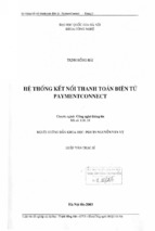
Fig. 1.
The vicious circle leading to large missiles and high-value
targets.
. . . . . . . . . . . . . . . . . . . . . . . . . . .
4
Fig. 2.
Features of the GNAT--IR homing antipersonnel micromissile
. .
6
Fig. 3.
Number of rounds fired by infantry rifles per enemy casualty
inflicted for recent United States conflicts
. . . . . . . . .
10
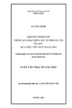
Example of a commercial thermoelectrically cooled PbSe IR
detector from the 1983 Catalog of Optoelectronics Inc.,
Petaluma, California
. . . . . . . . . . . . . . . . . . . . .
15
Hgl_x Cd Te detector performance data at 77K. “Performance
of comme~cial photon detectors,’? from The Infrared Handbook,
William L. Wolfe and George J. Zissis, US Government
Printing Office, 1978, p. 11-85 . . . . . . . . . . . . . . . .
16
PbSe detector performance data at 145 to 250K. Same source
asFig.5,
p. 11-73 (Ref. 29) . . . . . . . . . . . . . . . . .
17
Maximum detector temperature for blip operation vs energy
gaps for photon detectors. Same source as Fig. 5, p. 11-95
(Ref. 30)..
. . . . . . . . . . . . . . . . . . . . . . . . .
18
D;;vs bandgap and background temperature for photon detectors.
Same source as Fig. 5, p. 11-97 (Ref. 31) . . . . . . . . . . .
19
Fig. 9.
System resolution comparison
. . . . . . . . . . . . . . . . .
21
Fig. 10.
Multiaperture system response to a target at a particular
location
. . . . . . . . . . . . . . . . . . . . . . . . . . .
21
Fig. 11.
Matrix processing for multiaperture optical seekers . . . . . .
23
Fig. 12.
A possible multiaperture
configuration for GNAT . . . . . . . .
25
Fig. 13.
A sandwiched pair of aluminized PVDF sheets, poled in
opposing directions, bends as voltage is applied
. . . . . . .
29
Fig. 4.
Fig. 5.
Fig. 6.
Fig. 7.
Fig. 8.
v
GNAT--AN INFRARED HOMING ANTIPERSONNEL MICROMISSILE
by
Eugene H. Farnum
ABSTRACT
New technological discoveries make possible the development
of a very small, terminally guided missile that could greatly
increase the lethality of hand-held antipersonnel battlefield
weapons.
This missile could have a body diameter of only 20 mm
(0.8 in.), a length of 100 mm (4 in.), and a weight of 90 g
(-’3 Oz).
It could be launched from a hand-held weapon similar
to a rifle with -100 m/s initial velocity or dropped from aircraft to seek out and attack human targets on the battlefield.
The conceptual missile is powered by a small solid propellant
rocket capable of sustaining flight at 100 m/s for >1-km range.
The missile body and any fixed aerodynamic surfaces are made of
injection-molded plastic.
An infrared seeker, made with multiapertures,
glass lenses, and thermoeleccast, chalcogenide
trically cooled thin film infrared (IR) detectors, has a human
target acquisition range of -50 m with a field of view of -35 m.
This allows a capture angle of f2° at 500 m. The flight control
and guidance system uses a miniaturized linear gyroscope and
A very large scale
silicon
chip micromechanical
devices.
integrated (VLSI) circuit reads the IR sensors and supplies
flight correction
signals to aerodynamic
steering surfaces.
These steering surfaces are made of multilayer piezoelectric
to an
polymer bimorphs that bend by an amount proportional
applied voltage.
The warhead, which can weigh 1.5 OZ, is conceptually a high-explosive/pellet type. Operating power is supplied by a polyacetylene battery which is formed into a tube and
inserted as a liner for the missile case.
The missile is made of mass-produced modules that can be
easily assembled without mechanical moving parts or adjustment.
The modules include (1) the body with polyacetylene battery and
piezoelectric polymer steering fins; (2) the integral seeker,
guidance, and fuzing package;
(3) the warhead; and (4) the
rocket-assist motor.
Even though the IR seeker would only have limited background
discrimination capability and would depend on a temperature difference between the target and background, it would be substantially more effective at hitting a human target than an assault
It would be
rifle, requiring only approximate initial pointing.
effective at night and in adverse weather against unprotected
troops. This missile could dramatically reduce the cost/kill for
battlefield troops.
An airfield-dropped version need not have
a rocket assist and could carry a larger (2-oz) warhead.
The
●
●
following
new
technologies make this missile possible:
Piezoelectric polymer multilayer bimorphs have been demonstrated and used as fans to cool electronic instruments.
The material is available and the theory of operation is
well understood.
Development of an optimal adhesive and
techniques
are required.
improvements
in fabrication
The IR seeker and guidance package would need substantial
development effort, but the technology of multiaperture
optical seekers, IR transmitting glasses, thin film IR
detectors, silicon chip micromechanical accelerometers,
and custom VLSI circuits is presently state of the art.
Mechanical design of a miniaturized linear gyroscope must
be demonstrated.
“ Polyacetylene batteries represent an emerging technology
but are not a critical part of the missile design.
Currently available batteries would suffice.
o The missile body, warhead, and solid fuel rocket are current technology.
All these technologies are readily adaptable
production, assembly, and certification.
to automated mass
The concept originated in the Advanced Weapons Technology
group at Los Alamos National Laboratory.
Initial calculations
show that all elements of the system are compatible with the intended mission and capable of being developed to adequate
performance.
A 6.1 study to more fully explore the details of the concept, investigate potential materials, and identify problem areas
would be the next logical step. A study to determine the sensor
characteristics necessary for IR discrimination of soldiers on a
battlefield would allow a more accurate cost/kill number and aid
in preliminary design.
However, this will be a low-cost, massproduced missile, and high levels of discrimination are not required to achieve a favorable cost/benefit ratio.
I.
INTRODUCTION
A.
The Current State of Affairs
Self-guided
are gradually
weapons
(fire-and-forget)
replacing aimed and
This is primarily
man-guided weapons in all aspects of modern warfare planning.
because they have a greater kill probability than more conventional weapons and
offer a greater degree of protection
addition, the launch platform
(survivability) to the launch platform.
can engage more targets because
In
it is freed from
The exception
the need to follow the course of the weapon or observe the hit.
to the use of self-guided weapons is the infantry soldier.
Unarmored
infantry
troops
are
still
a
major
on
force
modern
most
battlefields-- certainly in the recurring third world conflicts and somewhat less
so in the envisioned
European
conflict.
Because
tracer ammunition, the current infantry weapon
of rapid automatic
fire and
(the M-16 assault rifle) cannot
be called unguided at ranges up to 300 m, but it is certainly not self-guided.
In fact, the assault rifle is notoriously ineffective in terms of the numbers of
1
rounds fired or the cost per enemy soldier killed.
Other weapons for attacking
unarmored
infantry
submunitions.
armored
Clearly,
as
However,
vehicles,
grenades,
are designed
which
the
blindly
unlike
to be
the
released
homing
antipersonnel
attempt
an
effect
on
the
used
submunitions
submunitions
are
nature
combat
systems as
defeating
bomblets
or
or small fragments.
antipersonnel
of infantry
for
unguided
an area kill using blast
a terminally guided, fire-and-forget,
profound
from smart weapons
weapon
could have
as air-to-air
heat-
seeking missiles have had on aircraft combat.
The main
not been
large,
reason that self-guided
developed
too
for antipersonnel
expensive,
and
The application
requires
low cost missiles.
mechanical
steering
control,
package, a target detection
ing
typically
uses
missions
insufficiently
elusive target.
small,
is that guided missiles
maneuverable
for
However,
a propulsion
hydraulics
have
are too
such a low-value,
a guided missile
unit,
a gyroscope
sensor, and a guidance computer.
target, but valuable
usually large.
namely guided missiles,
of missiles to attack small, low-value targets
and
is
sensitive gyroscopes and is expensive.
valuable
weapons,
targets
heavy.
Stabilization
has
to have
a
or stabilization
Mechanical
usually
steeremploys
A heavy, expensive missile must attack a
are encountered
at long ranges and are
Thus , the propulsion unit must be large with sufficient fuel for
the needed range and the detection sensor must be large and sensitive enough to
acquire the target at that range.
Then, the warhead must be sufficiently large
3
to defeat
the target when
the missile
has done its job.
Finally,
since this
large missile
is now also high value, more sophisticated
are justified
to assure high reliability and high kill probability.
As you can
1, a vicious circle develops which limits the minimum
size of the
see in Fig.
missile and the minimum value of the intended target.
this
circle
is a lightweight,
guidance and control
What is needed to break
compact steering technique; a low-cost stabili-
zation package; a simple, cheap detector; and a miniaturized
B.
computer.
The New Technologies
Newly developed and emerging technologies
lems and an infrared
(IR) homing, antipersonnel
is currently possible.
ation
missile
formance
terminal-homing
system
is
of each
a
missile with a mass of <100 g
It is my purpose, in this report, to propose a
for such a missile
effective
allow solutions to these prob-
and to show that, by using
antipersonnel
complex
subsystem
tradeoff
relative
missile
between
current
is feasible.
the
desired
configur-
technology,
an
The design of a
mission,
to the whole, and the cost.
the per-
I have made
no attempt in this study to optimize the design nor do I wish to restrict its
configuration
and
weight
to the one I have chosen.
of
the missile,
The choices I have made for the size
its aerodynamic
characteristics,
and the desired
performance of each subsystem are only loosely balanced with each other and with
the assumed
mission
and are not meant
to be more
than an example of what is
possible.
LAI16E6YR0 AHO MECHANICAL
&
LON6 FL16tJTTIME
LONG STABILIZATION
LON -RANGE Ill
d’
LONG RANGE
LAR6E WARHEAD
Fig. 1.
b,,,,,
LARGE MOTOR
LARGEGYRO
LARGE Ill SYSTEM
F:l’s,LE
d
HIGH COST
The vicious circle leading to large missiles.
The missile,
made
of
as shown in Fig.
piezoelectric
These devices
adjacent
polymer
2, would be steered by aerodynamic
or polymer/piezoelectric
ceramic
are made by laminating layers of piezoelectric
fins
multimorphs.
material
so that
layers are poled in opposing directions normal to the film plane.
A
voltage, applied to the stack, contracts the films on one side and expands those
on the other side causing a bending of the stack similar to a bimetallic
used
in thermostat
devices.
The deflection
reed
can be much greater than the con-
traction or expansion of the individual sheets and, as will be shown below, the
2-7
available force is adequate for this application.
Piezoelectric multimorphs
have
been
used
as vibratory
fans
to cool electronic
The use of
apparatus.
piezoelectric multimorphs for steering fins eliminates all mechanical components
in the flight control and allows purely electronic guidance.
If
straight-line
flight
is
desired,
the
guidance
and
stabilization
package must stabilize the missile until a target is acquired--a time of ~10 s.
This can be accomplished by a miniaturized vibrating cylinder or vibrating rod
8-15
linear gyroscope.
Vibrating
cylinder gyroscopes have been thoroughly
studied and have been made in sizes only a few times larger than desired for our
16
application.
Some innovation would be needed to achieve the desired low cost,
but smaller is generally cheaper and no technological impediments are apparent.
Alternatively,
a linear gyroscope similar to that used by the common house fly
10
to control its altitude may be used.
I will suggest below the use of a single
crystal
SiC fiber with a magnetic
sphere attached to one end to make a micro-
scopic linear gyroscope capable of short-term stabilization.
be
complemented
single-crystal
if
necessary
by miniature linear accelerometers made from
17,18
silicon wafers.
Such devices use a new technology and are
called micromechanical
Infrared
The gyroscope can
silicon devices.
detection and target acquisition would utilize thin film PbSe,
PbS , or
HgCdTe
IR
detectors
mounted
on
thin
film thermoelectric
coolers
needed.
The most efficient optical system is probably the multiaperture
“fly’s
eye” technology, which uses a small number of lenses each with a small n~ber
detectors with overlapping
if
of
fields of view (FOV); seven lenses with seven detec-
tors each have been used.
Thin-film
silicon detectors have already been made
with adequate defectivity, and research is progressing rapidly on HgCdTe. 19 IR20
transmitting lenses of germanium or chalcogenide glasses
can be mass produced
by simple molding processes.
for
our
application
Multiaperture
have already
systems of the same size as needed
demonstrated
sufficient
resolution
and have
5
6
I
generated
steering
Thermal Homer
commands
(MOTH) .21
for a homing
system
called Multiaperture
Optical
A major advantage of such a system is that the number
of detectors, and thus the required computing capacity for rapid image analysis,
is within
the
capacity
of
VLSI
circuit
technology
under
development
by
the
Defense Advanced Research Projects Agency (DARPA).
Considerable
computer
guidance and stabilization,
capacity
is
needed
for
the
image
processing,
In addition, several power
and steering functions.
supplies and other miscellaneous electronics will be needed for control, fuzing,
and other desired functions.
VLSI circuit technology can already put sufficient
computer power on a single chip that is <1 cm on a side.
chips
Commercial
computer
available with 256,000
random access memory in a few square
22
millimeters.
The entire electronics package could be designed as a single
VLSI
are
circuit
chip using
technology
being developed
in current DARPA programs.
The power supply must be capable of a few watts for -10 s and must have a long
shelf life.
Currently available lithium batteries have adequate size and power
23
for this use.
Polyacetylene batteries are an emerging technology which also
may prove useful.
The missile could be launched by airdrop or from a hand-held or machinemounted
launcher.
A small, solid fuel rocket motor
model rocket hobbyists) would be used to maintain
useful
range
(assumed to be -1
weight
limitations
used
in my
km).
example
(similar to those used by
the desired velocity for the
It is also possible within the size and
to increase
initial
rocket thrust suf-
ficiently to allow a recoilless launch.
The missile
warhead.
used
in this example
The envisioned
warhead
can carry a 1- to 2-OZ (30- to 60-g)
would
be a cylinder of close-packed
spheres surrounding -10 g of high explosive.
(46 g).
Although
this example
shotgun
more
innovative
has more propellant
shell.
It will be more
tungsten
This warhead would weigh ‘1.5 oz
concepts may be developed
for the warhead,
and about the same shot weight as a 12-gauge
than sufficient
for a contact
kill
and will
probably have a kill radius of a few feet.
In the discussion below, I will expand on these ideas to show that the
performance
rently
mission,
of each part
available
show
of the system
technology.
that
the missile
is adequate and then discuss the cur-
However,
could
be
we
must
cost
first
effective,
develop
define
an
intended
the nominal
target, and develop design criteria.
7
II.
OPERATIONAL ANALYSIS
A.
The Mission
The purpose of the proposed missile is to attack unmounted infantry per-
sonnel.
Usually these personnel will also be unarmored except for battle dress,
which may include lightweight body armor.
The battlefield may be anywhere, but
the
situations
mission
measurable
is
intentionally
limited
difference between
to
in which
the target and the background.
there
is
some
That is, where an
IR detector is used the target must be either hotter or colder than the background.
ature
The background threshold temperature will be determined by that temper-
which
targets.
includes most
The number
temperature
of the signals
of false
received
targets allowed
affects the probability
from “hot rocks”
above
the background
or false
threshold
of hitting the intended target and will be
determined by the cost of the missile.
If the missile can be made very cheaply,
it will be reasonable to attack every hot object on the battlefield knowing that
a fraction of these hot objects will be desired targets.
be situations where human targets are indistinguishable
IR detection and the missile will not be useful.
Obviously, there will
from the background with
Such situations can be deter-
mined in advance and detailed in the User’s Manual.
B.
Launch Options
The missile may be launched in different ways, depending on the desired
mission.
descent
It may be dropped by aircraft over enemy troops and follow a spiral
while
searching
for a target.
penser as a smart submunition.
hand-held
salvo
weapon
It may be dropped similarly by a dis-
Using its own propulsion, it may be fired from a
in the direction of a potential
from a motor-driven
platform.
target or it may be fired in
The trajectory between
launch and target
acquisition may be a straight line of sight, a ballistic path, or some more complicated path.
attack
The latter may be preprogrammed or programmed at time of fire to
targets
addition.
With
hidden
an
from
uncooled
view.
Similarly,
detector,
a
range-set
the missile
may
be
would
be
an
prepositioned
easy
to
“watch” a jungle trail or urban street and launch itself at any detected Larget
within its acquisition range.
c.
—
Cost Effectiveness
The
kill
vs
foremost
the
target
operational
value?
analysis
What
are
the
weapons
include bomblet
rifle.
The cost per kill of these weapons
8
submunitions,
questions
are, “What is the cost per
alternative
machine
gun
weapons?”
fire, and
is difficult
Alternative
the M-16
assault
to obtain, but in the
conflict the cost of M-16 ammunition exceeded $5000 per casualty
1
inflicted.
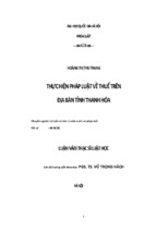
Figure 3 shows the number of rounds fired by infantry rifles vs
Vietnam
casualties inflicted for some TwenLieth
(5.56-mm NATO) weighs
The M-16 ammunition
Century conflicts.
12.5 g and has a volume of ‘4 cm3.
If the missile were
-100 times more effective at hitting a target at 100 g and a volume of 30 cm3,
it would be about
10 times more
volume) than the M-16.
effective
support
for logistics
(weight and
There is obviously a lot of room for improvement in this
area and the size and weight of the proposed missile are well within the range
Nevertheless,
of acceptable effectiveness.
delicate balance
that determines
we must constantly keep in mind the
cost effectiveness
and the vicious
circle of
missile size described in Fig. 1.
D.
The Nominal Target
A typical human being at rest generates about 100 W of heat from meta-
bolic
processes.
vection
from
necessary,
This
exposed
by
heat
is rejected
surfaces,
evaporative
by
cooling
from the body
transfer
by
to the air
(perspiration).
radiation
in breathing
Metabolic
heat
and
con-
and,
output
if
in-
creases with increasing activity, and the body attempts to regulate its temperature by raising skin temperature and perspiring.
the skin temperature
ditions.
above 310 K (98.6°F), perspiration
In cold conditions
preserve heat.
Since the body cannot raise
skin temperature
decreases
takes over in warm conas the body tries to
This decrease is limited since temperatures
(79°F) become uncomfortable
Let us try to make
of less than 299 K
and require clothing to reduce the radiating area.
a typical
(average, nominal, or guessed)
case by assuming
that the body generates 100 W, that it rejects this heat over the entire 2 m2 of
body
area,
and
breathing.
that
of 300 K.
the cooling
is by perspiration,
temperature
Thus , for a background
differences
The
convection,
With an emissivity
and
of
to a temperature difference of 4 K at a radiating temper-
will be 308 K (95”F).
unusual.
of
In this case the radiated heat is 21 W/m2.
0.8, this corresponds
ature
60%
of 304 K (88°F), the skin temperature
Note that this is quite a conservative estimate and that
between
ideal blackbody
regions is shown in Table 1.
skin and background
emission
of more than 10 K are not
at 308 and 304 K
in various
spectral
—
x’
—
x/
x/
/
x
I
Wwl
I
I
WWII
KOREA
I
VIETNAM
CONFLICT
Fig. 3.
Number of rounds fired by infantry rifles per
enemy casualty inflicted for recent United
States conflicts.
TABLE I
BLACKBODY RADIATION FOR A TARGET AND BACKGROUND
IN SEVERAL WAVELENGTH BANDS
Wavelength Range
Target
Emitted Flux
at 308 K
Background
Emitted Flux
at 304 K
(pm)
(W/m2)
(W;m2)
All
510.0
484.0
26.0
8.5-12.5
132.0
124.0
8.0
8-9
34.3
32.0
2.3
9-1o
35.0
32.8
2.2
3.9
4.5
3.4-4.8
1.8-2.8
10
Net
Emitted Flux
.
(W/mz)
25 x 10-2
1.9 x 10
0.6
-2
6
X
10-3
Atmospheric
transmission bands at 8.5 to 12.5 (the 8- to 12-pm band) and
3.4 to 4.8 pm (the 3- to 5-pm band) are commonly used for IR detection to avoid
atmospheric absorption.
Thus we expect a person, in rejecting his 100 W of heat, to radiate a net
flux of 0.6 W/m2
in the 3- to 5-pm band and 8 W/m2 in the 8- to 12-pm band.
The background temperature of 304 K taken for this typical case will correspond
to
the
battlefields
and
will
model
target
carefully
ature, T
temperature
discussed
Possible
or less easy respectively.
Attempts to
24
controlled backgrounds
have been relatively successful.
For
a field of grass
can be described
by an effective blackbody
temper-
different from the temperature of the air, Tair, which is given by
e’
temperatures
are
air
in
‘
degrees
centigrade.
This
reflected solar radiation, hot rocks, and metal surfaces.
ation
earlier.
detection more
Te = -14.3 + 1.6 T
where
threshold
can have average temperatures between 253 and 315 K (-5 to +107”F)
make
example,
background
can be
significant
average background
does
not
account
for
Reflected solar radi-
in the IR but the reflectance of the target and the
are both low and probably
about the same (-10%).
Hot rocks
and metal surfaces can obviously pose a discrimination problem for a nonimaging
IR system on a warm sunny day.
missile
I believe that the usefulness of this proposed
under such conditions must be determined experimentally
systems.
In addition, these conditions,
with prototype
least favorable for good IR detection,
are also most favorable for alternative weapons, such as the M-16 rifle.
III.
CURRENT DESIGN CRITERIA
To demonstrate
that technology
is adequate to make an effective missile,
some design parameters must be specified.
istics
and
necessary
background
to make
for
a “typical”
the missile
I have selected the target characterscenario.
a cost-effective
Performance
addition
characteristics
to the antipersonnel
arsenal must also be selected before even a preliminary design can be attempted.
I have
taken the case of a missile
target 500 m away.
fired from a hand-held weapon at a
The shooter is assumed to be able to point his weapon within
f2° of the location of the target at missile arrival (a full-choke shotgun with
a range of 50 m,
requires pointing
500 m is 32 m diam.
f0.6°).
A field of view
(FOV) of k2° at
If the missile cannot acquire the target at 500 m, the FOV
11
must
still be 32 m diam at the acquisition
depends
on
the
sensitivity.
ability
is determined
the steering
distance,
which
in
turn
Thus , the optical FOV
depends
on the detector
However, it does no good to have the FOV cover an area larger than
the missile’s
missile
acquisition
distance.
surfaces
to turn and attack.
The minimum turning radius of the
by the maximum aerodynamic
and on the air speed.
force that can be exerted by
The minimum turning radius also
depends on wing area, aerodynamic design, missile mass, and moment of inertia;
however, the steering force possible with piezoelectric bimorphs is limiting for
our
case.
Thus ,
aerodynamic
the
steering
limitations
of
detector
force are interdependent
acquisition
distance
and
in the missile design, and both
determine the available FOV and airspeed.
The missile could cover more area and have a larger FOV with a slow speed
and large wings.
wing)
However,
in addition to the limitation on missile
size imposed by our desire
ficiently
fast so that the target
to minimize
cost, the missile
cannot detect
the attack
(and thus
must be suf-
and evade
it.
A
person observing a missile coming toward him can either shield himself or remove
himself
from the FOV.
ceivable
Typical eye-hand reaction time is 0.2 s, so it is con-
that a person could shield themselves
16 m out of the FOV in that short a time.
in 0.5 s.
They could not move
Since the proposed 2-cm-diam missile
will become visible against a good background at a range of 30 to 50 m, an air25
speed of 100 m/s should be adequate for the missile to be effective.
This
desired.
speed
is
also
consistent
with
the
wing
area and turning
radius
A number of discussions have suggested that it may be desirable for a
soldier to be able to avoid the missile if he sees it coming soon enough.
arguments
are based
on distractive
and psychological
advantages;
These
further con-
sideration of this point will be left to strategists and the interested reader,
since there is no reason why the missile speed could not be reduced or increased
within limitations discussed below.
Finally,
the warhead
must be sufficient
missile traveling at 100 m/s would probably
it hit a vulnerable
spot.
Since
to kill
the target.
A
100-g
kill a person without a warhead if
the soldier may be
surrounded
by other hot
objects, which may decoy the missile, such as his rifle or a pile of just-fired
cases, a kill radius of -1 m for the warhead is preferred.
The criteria adopted for the missile proposed herein are based on a scenario which may not have much relevance to the mission envisioned by the reader.
12
It will be the task of the reader, skilled in the art of combat and with experience which shows him where such a missile is needed, to define criteria for his
desired mission.
Iv.
TARGET DETECTION
A.
Detectors
The
limit to maximizing
the target acquisition
distance
is the sensi-
Sensitivity is generally represented by
l/2w-l
or D::, expressed in units of cm Hz
$
tivity of and noise in the IR detector.
a parameter
called
the defectivity
which depends on the detector material,
the material purity,
detector design, and the detector temperature.
parameters
time
of the electro-optical
(or the
Carefully
ations.
inverse
designed
called
detectors
application) , this
Photodetector
type
(BLIP),
can have
and background
temperature.
total noise limited by background
detectors
detector
its
and
frequency),
integration
(probably
is called
defectivity,
the best
a Background
D-~BL1p, can
be
vari-
choice
for this
Limited
Infrared
determined
for
a
integration time, t, bandwidth, AA, and background
peak’
It can be shown from first principles of detector physics that
specific wavelength,
temperature, Tb.
of
The defectivity also depends on
system, such as wavelength band,
flicker
In the case of photon
the care taken in
A
the noise equivalent power on a detector array from an optical system is given
by
r
N-El?=# /’; —
2Nt
(1)
‘
where
f is the ratio of focal length to diameter of the lens system,
~ is the lens diameter,
Q is the solid angle of the FOV,
N is the number of detectors,
D>% is the defectivity
of a single detector for the conditions of interest,
and
t is the integration time (sometimes called frame time).
The ratio of the power radiated by the target that falls on the lens to the
NEP
is the signal-to-noise
ratio (SNR) of the detection
system.
The distance
from the target for which SNR = 1 will be called the acquisition range, although
there is reason to believe that multiaperture
systems can do somewhat better, as
will be discussed below.
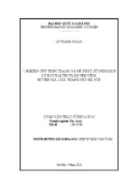
Infrared detectors are commercially available
and the 8- to 12-pm bands.
diam transistor
thermoelectric
26
for both the 3- to 5-pm
These are available in packages as small as 4.7-mm-
cans, as shown in Fig. 4.
They can be supplied with two-stage
coolers, capable of detector operations below 230 K with only a
few watts electrical cooling power.
Examples of commercial detector performance
The 8- to 12-pm band will use Hg ~_xCdxTe detectors,
are shown in Figs. 5 and 6.
Detectivities of
the 3- to 5-pm band is best served by PbSe detectors.
10
the order of 10
cm Hz% W-l appear to be the present state of the art although
27
theoretical values are higher.
while
It
will
probably
desired
defectivity,
maximum
temperature
be
necessary
especially
to
cool
the
detectors
in the 8- to 12-pm band.
to
achieve
the
Figure 7 shows the
for BLIP operation as a function of background photon flux.
For the 8- to 12-pm band, temperatures of -120 K are needed for BLIP operation.
-1
10
If BLIP operation is achieved, the defectivity can be >10
cm Hz%
for a
300 K background
temperature, as shown in Fig. 8.
off for long integration
The defectivity
times because of an elusive
also falls
l/f noise associated with
all detectors.
In
summary,
the
following
represents
the
current
state-of-the-art
in
photon detectors for the IR when observing a 300 K background.
3- to 5-pm band--detector
temperature <250 K
frame frequency ~ 300 Hz
material - PbSe
defectivity D+’ = 10
10
cm Hz% W-l
$ w-l
11
cm Hz
theoretical limit D;’ ~ -2 x 10
8- to 12-pm band--detector
temperature <150 K
frame frequency ~ 300 Hz
material - Hgl-xCdxTe
-1
defectivity D:’ =5xlogcmHz%W
theoretical limit D* = ‘3 x 10
Cooling
may be achieved
rather easily by
10
cm Hz* W-l
thermoelectric
coolers
detectivities
and
if
refrigerators,
micro-sized
Joule-Thompson
~olo
cm Hz* W-l are needed, some detector cooling will be required.
14
or by
of
I
OptoEledronic~inc.
SPECIAL
OTC-12-5
SERIESTWO STAGE
THERMOELECTRICALLY COOLED
LEAD SELENIDEDETECTORS
FEATURES
PEAK SENSITIVITY
COMPARABLE TO DEVICES
OPERATING AT 77 K
THERMOELECTRICALLY COOLED
PROVEN SOLIDSTATE STABILITY
HERMETICALLY SEALED
RUGGED, COMPACT
IMMEDIATE DELIVERY
LOW COST
BRIEF DESCRIPTION
OTC-12-5 series infrared sensors are OPTOELECTRONICS,
Inc. lead selenide (PbSa) detectors mounted on two stage
thermoelectric
coolers end packaged in TO-5 cans.
Designed for use in applications requiring detectors with
extremely high sensitivity in the lpm to 5#m spectral region,
these sensors offer en economical means for obtaining cooled
photorxmductive
detector performance
without the bulk end
inconvenience of liquid cooling.
OTC-12-5 detector packages are fully evacuated end hermetically sealed, incoqmrating
advanced
packaging
concepts
such es all fused end welded ccmstruction; in addition, the
PbSe detector elements in these sensors are fully passivated
with a protective overcoat. This paesivation technique, developed by OPTOELECTRONICS,
Inc., eliminates
instabilities
generally associated with PbSe datectors when they are subjected to visible end/or ultraviolet radiation.
Particularly suitable for use in high volume, low cost systems operating in the Ipm to Spm spectral region, OTC-12
series detectors provide peek sensitivity, comparable to liquid
nitrogen cooled (77° K)PbSe, end performance
end reliability
far exceeding
that of any other previously available photodetector of comparable size and cost.
Verious standard beat sirrks (optional), including a TO-37
mounting base, are available for use with these detectors.
1
*
i
“c”’”
i-
t
MC u..
i_-
<*,._
Fig. 4.
Example of a commercial thermoelectrically cooled PbSe IR
detector. Reprinted with permission from the 1983 Catalog
of Optoelectronics Inc. , Petaluma , California .
15
- Xem thêm -