Thin Film Deposition
& Vacuum Technology
THIN FILM DEPOSITION & VACUUM TECHNOLOGY
By
Stefan Cannon Lofgran
A senior thesis submitted to the faculty of
Brigham Young University–Idaho
in partial fulfillment of the requirements for the degree of
Bachelor of Science
Department of Physics
Brigham Young University–Idaho
April 2013
c Stefan Lofgran
2013
All Rights Reserved
Brigham Young University–Idaho
Department Approval
of a senior thesis submitted by
Stefan Cannon Lofgran
This thesis has been reviewed by the research committee, senior thesis coordinator and department chair and has been found to be satisfactory.
Date
David Oliphant, Advisor
Date
Ryan Nielson, Committee Member
Date
Stephen McNeil, Senior Thesis Coordinator
ABSTRACT
THIN FILM DEPOSITION & VACUUM TECHNOLOGY
Stefan Cannon Lofgran
Department of Physics
Bachelor of Science
The study and development of thin films via physical vapor deposition has
played a significant role in the development of optical coatings, semiconductors, and solar cells. Closely related to the study of thin films is the development of vacuum technology and systems capable of reaching pressures
suitable for growing uniform films at reasonable deposition rates. This paper
explores the method of physical vapor deposition known as thermal evaporation via resistive or Joule heating as a means for growing thin aluminum
(Al) films on a mineral glass substrate. Methods for measuring thickness are
also discussed and investigated in an attempt to determine the experimentally produced film thickness. A detailed explanation of the development and
operation of the vacuum system in which the Al films were grown is given as
well as future improvements that could be made.
iii
ACKNOWLEDGEMENTS
To my loving wife & family who have supported me the
whole way, and to David Oliphant who has guided me on
this project.
iv
Table of Contents
Abstract . . . . . .
Acknowledgements
List of Figures . . .
List of Tables . . .
.
.
.
.
.
.
.
.
.
.
.
.
.
.
.
.
.
.
.
.
.
.
.
.
.
.
.
.
.
.
.
.
.
.
.
.
.
.
.
.
.
.
.
.
.
.
.
.
.
.
.
.
.
.
.
.
.
.
.
.
.
.
.
.
.
.
.
.
.
.
.
.
.
.
.
.
.
.
.
.
.
.
.
.
.
.
.
.
.
.
.
.
.
.
.
.
.
.
.
.
.
.
.
.
.
.
.
.
.
.
.
.
.
.
.
.
.
.
.
.
Page
.
iii
.
iv
. vii
. viii
1 Introduction
1.1 A Brief History of Thin Film &
Vacuum Technology . . . . . . . . . . . . . . . . . . . . . . . . . . . .
1.2 Review of Theory . . . . . . . . . . . . . . . . . . . . . . . . . . . . .
2 Experimental Design & Setup
2.1 Vacuum System Design . . . . . . . . . . . . . . . . . . . . .
2.1.1 Recent Developments . . . . . . . . . . . . . . . . . .
2.1.2 Using a Viton Gasket . . . . . . . . . . . . . . . . . .
2.1.3 Vacuum Conditioning . . . . . . . . . . . . . . . . . .
2.2 Deposition System Design . . . . . . . . . . . . . . . . . . .
2.2.1 The Original Experiment . . . . . . . . . . . . . . . .
2.2.2 New Crucibles & Improved Temperature Calculations
2.2.3 Power Supplies & Feedthroughs . . . . . . . . . . . .
2.2.4 Substrate Holder Design . . . . . . . . . . . . . . . .
3 Procedures & Documentation
3.1 Equipment Documentation . . . . . .
3.1.1 Silicon Heating Tape . . . . .
3.1.2 Type C Thermocouple . . . .
3.1.3 Quartz Crystal Microbalance
3.1.4 Residual Gas Analyzer . . . .
3.1.5 Crucibles, Baskets, & Boats .
v
.
.
.
.
.
.
.
.
.
.
.
.
.
.
.
.
.
.
.
.
.
.
.
.
.
.
.
.
.
.
.
.
.
.
.
.
.
.
.
.
.
.
.
.
.
.
.
.
.
.
.
.
.
.
.
.
.
.
.
.
.
.
.
.
.
.
.
.
.
.
.
.
.
.
.
.
.
.
.
.
.
.
.
.
.
.
.
.
.
.
.
.
.
.
.
.
.
.
.
.
.
.
.
.
.
.
.
.
.
.
.
.
.
.
.
.
.
.
.
.
.
.
.
.
.
.
.
.
.
.
.
.
.
.
.
.
.
.
1
1
4
.
.
.
.
.
.
.
.
.
9
9
9
10
12
14
14
15
17
18
.
.
.
.
.
.
21
21
21
22
23
24
25
.
.
.
.
.
25
26
26
27
28
4 Thin Film Deposition Rates
4.1 Initial Rate Calculations . . . . . . . . . . . . . . . . . . . . . . . . .
4.2 Effects of Slide Outgassing . . . . . . . . . . . . . . . . . . . . . . . .
29
29
31
5 Future Experiments & Summary
5.1 Improving Film Quality . . . . . . . . . . . . . . . . . . . . . . . . .
5.2 Improved Deposition Rates . . . . . . . . . . . . . . . . . . . . . . . .
35
35
36
Bibliography
38
Appendix A
40
Appendix B
42
Appendix C
45
Appendix D
49
Appendix E
50
Appendix F
53
3.2
3.3
3.1.6 Power Supplies . . . . . .
Vacuum Procedures . . . . . . . .
3.2.1 Pumping to Low Vacuum
3.2.2 Pumping to High Vacuum
Deposition Procedure . . . . . . .
vi
.
.
.
.
.
.
.
.
.
.
.
.
.
.
.
.
.
.
.
.
.
.
.
.
.
.
.
.
.
.
.
.
.
.
.
.
.
.
.
.
.
.
.
.
.
.
.
.
.
.
.
.
.
.
.
.
.
.
.
.
.
.
.
.
.
.
.
.
.
.
.
.
.
.
.
.
.
.
.
.
.
.
.
.
.
.
.
.
.
.
.
.
.
.
.
List of Figures
1.1
1.2
1.3
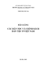
RGA cracking patterns . . . . . . . . . . . . . . . . . . . . . . . . . .
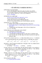
Langmuire-Knudsen angle dependence . . . . . . . . . . . . . . . . .
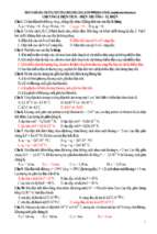
Initial deposition system configuration . . . . . . . . . . . . . . . . .
2.1
2.2
2.3
2.4
2.5
2.6
2.7
2.8
2.9
2.10
BYU-Idaho Vacuum system . . .
25” OD CF Flange . . . . . . . .
O-ring over compression failure .
RGA P vs T graph . . . . . . . .
Various boats and baskets [1] . .
Broken tungsten baskets . . . . .
Broken quartz crucibles . . . . . .
New crucible holder configuration
Old crucible configuration . . . .
Substrate holder design . . . . . .
.
.
.
.
.
.
.
.
.
.
10
11
12
14
15
16
17
18
19
20
3.1
3.2
Quartz Crystal Microbalance Positioning . . . . . . . . . . . . . . . .
Crucible & basket combination . . . . . . . . . . . . . . . . . . . . .
24
25
4.1
4.2
4.3
Filmed slide projection . . . . . . . . . . . . . . . . . . . . . . . . . .
Average change in slide mass over time . . . . . . . . . . . . . . . . .
Change in slide mass between consecutive days . . . . . . . . . . . . .
30
33
34
vii
.
.
.
.
.
.
.
.
.
.
.
.
.
.
.
.
.
.
.
.
.
.
.
.
.
.
.
.
.
.
.
.
.
.
.
.
.
.
.
.
.
.
.
.
.
.
.
.
.
.
.
.
.
.
.
.
.
.
.
.
.
.
.
.
.
.
.
.
.
.
.
.
.
.
.
.
.
.
.
.
.
.
.
.
.
.
.
.
.
.
.
.
.
.
.
.
.
.
.
.
.
.
.
.
.
.
.
.
.
.
.
.
.
.
.
.
.
.
.
.
.
.
.
.
.
.
.
.
.
.
.
.
.
.
.
.
.
.
.
.
.
.
.
.
.
.
.
.
.
.
.
.
.
.
.
.
.
.
.
.
.
.
.
.
.
.
.
.
.
.
.
.
.
.
.
.
.
.
.
.
.
.
.
.
.
.
.
.
.
.
5
6
7
List of Tables
1.1
Vacuum quality pressure ranges . . . . . . . . . . . . . . . . . . . . .
2
3.1
3.2
3.3
Silicon Heat Tape Specifications . . . . . . . . . . . . . . . . . . . . .
Type C thermocouple specifications . . . . . . . . . . . . . . . . . . .
Genesys 60-12.5 power supply details . . . . . . . . . . . . . . . . . .
22
23
26
viii
Chapter 1
Introduction
1.1
A Brief History of Thin Film &
Vacuum Technology
Vacuum technology is becoming increasingly important within physics due to its
several applications. The ideal vacuum is a space devoid of all particles. All vacuum
systems aren’t created equal, and like many things in physics actual vacuum
systems fall short of the ideal. The base pressure a system maintains determines the
quality of its vacuum. These levels aren’t strictly defined, but are generally
described as rough, low, medium, high, or ultra high (see Table 1.1). The most
obvious factors determining the type of vacuum achieved are the equipment used
and the system configuration. Before delving into the details of vacuum design and
its importance in developing thin films it will be beneficial to review a brief history
of how vacuum systems were first developed.
One of the first contributors to vacuum technology was Otto von Guericke. Von
Guericke developed the first vacuum pump sometime in the 1650’s[2]. With his
pump, he was able to study some of the most basic properties of vacuums. Von
Guericke believed that his pump pulled the air out of a container, which is actually
incorrect. Vacuum pumps cannot pull the gases out of a container rather they
1
Table 1.1: Vacuum quality pressure ranges
create a difference in pressure which causes the gas in the high-pressure area to
move to the low-pressure area. Essentially, a vacuum pump generates a vacuum by
creating pressure differences, which creates a flow of gas that exits the chamber at a
rate faster than the rate at which gas enters the chamber.
Aside from Von Guericke, there were several other contributors to what is now
considered modern vacuum technology. Many of these individuals lived before or
during the same time as Otto von Guericke. Evangelista Torricelli, the man who the
unit of pressure Torr is named after, was one of the first to recognize a sustained
vacuum while observing mercury in a long tube. He noted his discovery, but never
actually published his findings because he was more interested in mathematics.
Hendrik Lorentz, Blaise Pascal, Christiaan Huygens, and others all played crucial
roles in defining and developing the fundamental principles upon which modern
vacuum systems run.
Modern vacuum technology is constantly adapting to be used in a broader range
of applications in a plethora of disciplines within physics and engineering, such as
vacuum packaging, welding, and electron microscopes. Even though vacuum
technology has developed rapidly since the 1600’s, what most would define as
modern vacuum technology isn’t that old. Scientists and engineers developed most
of the technology that we use today during and after World War II. During the
2
period of development after World War II people began to revisit thin films and
explore the possibilities of their uses in industry, particularly in the semiconductor
industry.
One of the most important applications of vacuum systems is the development of
thin films. Physical vapor deposition (PVD) is just one method of producing thin
films. Michael Faraday pioneered the first PVD process in the early 1800’s [1].
Many sub processes fall under the description of PVD including electron beam,
sputtering, thermal, and plasma arc deposition methods. At BYU-Idaho the
method used to produce thin films is a thermal evaporative deposition. Thermal
evaporation deposition is the most basic method used to produce thin films. The
first use of the term PVD was used in C. F. Powell, J. H. Oxley, and J. M. Blocher
Jr.’s book Vacuum Coatings in 1966 [3]. They were not the first to use PVD
methods for developing thin coatings either, but their text helped to establish and
clarify the PVD processes that were known by that time. Since Powell, Oxley, and
Blocher’s publication scientists have devised many new methods for growing films.
Recent developments in the past few decades have produced methods capable of
growing alloy films and processes suitable for large scale production in order to
better meet the demands of consumers.
Today’s society overlooks the importance of vacuum coatings in products they
use. The semiconductor industry relies heavily on thin film technology to produce
flash memory and computer chips. Companies developing optical products often use
optical polarizers and beam splitters in their designs. Other industries also use thin
film technology most of which is for cosmetic purposes, such as mirrors and toys.
3
1.2
Review of Theory
At this point an in depth exploration of gas flow regimes will not be discussed, but
if the reader is interested they would benefit greatly from reading O’Hanlon’s A
User’s Guide to Vacuum Technology [4]. Film quality and vacuum system pressure
are inseparably connected. Uniformity and purity are the main elements in
determining a film’s quality. Uniformity is an issue that was not addressed during
the development of the BYU-Idaho deposition system. Getting the system to
function properly is a prerequisite to tasks concerning the film uniformity. The
purity of the material prior to deposition is the largest factor in determining the
films purity. The second biggest factor is most likely the gas composition and
pressure of the system in which the film was developed. Vacuum technicians know
that these two elements of a vacuum system are difficult to control. At BYU-Idaho,
we focus on trying to analyze these factors rather than control them at the present
time. To analyze the gas composition in our vacuum system we rely on a 200 AMU
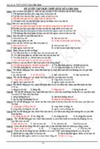
residual gas analyzer (RGA). The RGA is a quadrapole mass spectrometer that can
determine the atomic mass of gas molecules in a system by ionizing the particles
and measuring the change in voltage of an electrode when the ionized gas collides
with it. The RGA uses the voltages to then produce cracking patterns used to
determine the gas composition of the chamber (see figure 1.1).
A substantially low pressure is required to prevent film oxidation and reduce the
contaminant density. A pressure of 10−5 Torr is sufficient, but lower pressures would
help reduce the density of contaminants in the film. At 10−5 Torr the mean free
path of gas in the chamber is approximately 8 meters, which without the unit of
measurement is often referred to as the Knudsen number. The mean free path can
4
Figure 1.1: RGA cracking patterns
be calculated using the following equation
kB T
,
l=√
2πd2 P
(1.1)
where kB is the Boltzman constant, T is the temperature in Kelvin, d is the
diameter of the molecule in meters, and P is the pressure in Pascals. As the mean
free path of the gas particles increases, so does the Knudsen number. When the
Knudsen number is close to or greater than one, gas particles obey principles of free
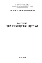
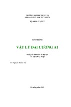
molecular flow more than viscous flow. The Langmuire-Knudsen equation is
founded on the assumption that the molecules follow a molecular flow regime. The
Langmuire-Knudsen equation is
r
Rm = Cm
M
1
cos θ sin φ 2 (Pe (T ) − P ),
T
r
(1.2)
mol·K
where Rm is the rate per unit area of the source, Cm = 1.85 × 10⁻² s·T
a constant,
orr
M is the gram-molecular mass of the deposition material, T is the temperature of
5
Figure 1.2: Langmuire-Knudsen angle dependence
the deposition material, θ is the angle between the normal of the source and the
substrate, φ is the angle normal to the surface of the substrate and crucible, r is the
distance between the crucible and substrate, and P and Pe are the system pressure
and evaporant partial pressure in Torr respectively. Another assumption of the
Langmuire-Knudsen equation is that the evaporant molecules will travel from the
crucible where they are heated to the substrate without “picking” up any other gas
particles in the chamber (see figure 1.2). Subsequently, a decrease in the base
pressure of the vacuum will also reduce the number of particles “picked” up as they
flow towards the substrate to be deposited.
The Langmuire-Knudsen equation necessitates the use of other methods and
equations to calculate an accurate deposition rate. Among these is Stefan-Boltzman
equation for blackbody radiation:
P = IV = σ�AT 4 ,
(1.3)
where P is the electrical power through the crucible, I is the current, V is the
voltage, σ is the Stefan-Boltzman constant, � is the emissivity, A is the surface area
6
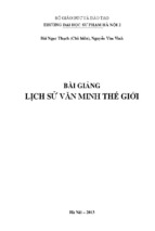
Figure 1.3: Initial deposition system configuration
of the black body, and T is the temperature. Solving for T we find
T =[
IV 1
]4 .
σ�A
(1.4)
I also used an experimentally derived equation for determining the partial pressure
of liquid Al[5] given by
log P = −
15993
+ 12.409 − 0.999 log T − 3.52 × 10⁻⁶ T,
T
(1.5)
where P is the pressure in Torr and T is the temperature. There are, of course,
many other methods capable of deriving the necessary quantities. At the time of the
initial experiment, these were the best approximations available to us, but with the
addition of a type C thermocouple, new vacuum feedthrough, and power supply; our
capability to derive the temperature more accurately has improved. Feasible
alternatives to approximating the crucible temperature solely by using a blackbody
approximation include incorporating power loss/transmission calculations and the
use of a thermocouple.
7
Understanding the fundamentals of vacuum theory can prevent many of the
complications that diminish the accuracy and precision of collected data.
Recognizing the sources of leaks in a vacuum system is one item that is of particular
interest for experimentalists. A variety of sources lead to unwanted gas added to the
chamber by leaks. Vacuum leaks are often due to the pressure gradient that exists
within a vacuum, which creates a surplus of interesting and inimical problems. Thus
vacuum leaks should be addressed prior to experimentation. At a standard
temperature and pressure, almost everything absorbs water vapor and other gases.
One factor that affects how much water vapor is absorbed by a material is the
humidity. Inside a vacuum, these materials release the gases they absorbed because
the same forces that helped trap gasses in them have diminished. As a result,
preparing materials prior to use inside the chamber and considering their impact on
the data is an important step in the experimental process.
All materials will experience some outgassing within a vacuum chamber. A
judicious selection of materials will reduce the effects of outgassing, or leaking of
gas, from materials that are used. For this reason, conditioning of the vacuum
chamber and, if possible, all the materials used in the chamber is also an important
step of experimentation. Chemical cleaning or pre-exposure to vacuum pressures are
both ways to condition materials for use in vacuum. More technical processes such
as those used in developing semiconductors have prescribed standard methods for
cleaning materials prior to use in vacuum.
8
Chapter 2
Experimental Design & Setup
2.1
2.1.1
Vacuum System Design
Recent Developments
BYU-Idaho purchased the vacuum chamber, pressure gauges, roughing pump, and
residual gas analyzer; but received the oil diffusion pump and gate valve as a
donation from another university. The important details about almost all of the
equipment are known. However, we don’t know the material or manufacturer of the
O-ring used with the chamber.
Within the past year, improvements to the vacuum system have helped to achieve
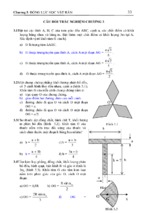
lower pressures more consistently. Initially, the BYU-Idaho vacuum chamber
operated with only a couple thermocouple pressure gauges, ion pressure gauge, oil
diffusion pump backed by a rotary vane roughing pump, viewport, RGA, and single
high voltage electrical feedthrough (The current design can be seen in figure 2.1).
While these are sufficient to achieve pressures suitable for PVD, there is always
room for improvement.
9
Figure 2.1: BYU-Idaho Vacuum system
The goal that drives development of the vacuum system is that of achieving the
lowest base pressure possible. It is far more difficult to achieve an ultra-high
vacuum than it is to reach a low vacuum. Fortunately, the oil diffusion pump that is
used has a very high throughput rate of about 2,000 L/s. This makes it possible to
achieve pressures as low as 10−8 Torr with the current pump configuration. Despite
this advantage, other elements of the system do more to limit the achievable
pressure than the pump.
2.1.2
Using a Viton Gasket
A pitfall of the current design is lack of smaller ports to transfer materials in and
out of the chamber. The system has a cylindrical design with feedthrough ports
along the sidewall and the chamber separates above the feedthroughs with a 25”
outer diameter (OD) conflat flange (CF) (this can be seen in figure 2.2). The Viton
10
- Xem thêm -