MINISTRY OF EDUCATION AND TRAINING
NATIONAL UNIVERSITY OF CIVIL ENGINEERING
Duong Thanh Huan
STATIC AND VIBRATION ANALYSIS OF FGM
DOUBLY-CURVED SHELLS IN THERMAL
ENVIRONMENT
Major: Engineering Mechanic
Code: 9520101
SUMMARY OF DOCTORAL DISSERTATION
Hanoi - 2019
The work was completed at:
NATIONAL UNIVERSITY OF CIVIL ENGINEERING (NUCE)
Academic supervisor :
1. Assoc. Prof. PhD. Tran Huu Quoc – NUCE
2. Assoc. Prof. PhD. Tran Minh Tu – NUCE
Peer reviewer 1: Prof. PhD. Nguyen Tien Khiem
Institute of Mechanics
Peer reviewer 2: Prof. PhD. Nguyen Thai Chung
Military Techical Academy
Peer reviewer 3: Prof. PhD. Nguyen Tien Chuong
Thuyloi University
The doctoral dissertation will be defended at the level of the State
Council of Dissertation Assessment's meeting at the National University of
Civil Engineering.
at ..... hour .....', day ..... month ..... year 2019
The dissertation is available for reference at the libraries as follows:
- National Library of Vietnam;
- Library of National University of Civil Engineering;
LIST OF PUBLISHED WORKS BY AUTHOR RELATED TO THIS
DISSERTATION’S TOPIC
1. Tran Minh Tu, Tran Huu Quoc, Duong Thanh Huan, and Nguyen Van Long (2014), Vibration
analysis of functionally graded plates using various shear deformation plate theories,
rd
Proceedings of the 3 International Conference of Engineering Mechanics and Automation ICEMA3, University of Engineering and Technology – Vietnam National University, ISBN:
978-604-913-367-1, trang 580-587.
2. Trần Minh Tú, Trần Hữu Quốc, và Dương Thành Huân (2015), Phân tích tĩnh và động
Panel trụ làm bằng vật liệu có cơ tính biến thiên (FGM) theo lý thuyết biến dạng cắt bậc nhất
(FSDT), Tuyển tập công trình Hội nghị Khoa học toàn quốc Cơ học vật rắn biến dạng lần thứ
XII, Thành phố Đà Nẵng, ISBN: 978-604-82-2028-0, Tập 2, trang 1506-1513.
3. Trần Hữu Quốc, Dương Thành Huân, Trần Minh Tú, và Nghiêm Hà Tân (2017), Phân tích
Panel trụ FGM chịu uốn có xét đến ảnh hưởng của nhiệt độ - Lời giải giải tích và Lời giải số,
Tạp chí Khoa học Công nghệ Xây dựng, ISSN: 1859-2996, Tập 11 số 2, trang 38 – 46.
4. Duong Thanh Huan, Tran Minh Tu and Tran Huu Quoc (2017), Analytical solutions for
bending, buckling and vibration analysis of functionally graded cylindrical panel, Vietnam
Journal of Science and Technology. 55(5): p. 587-597, DOI: 10.15625/2525-2518/55/5/8843.
5. Duong Thanh Huan, Tran Huu Quoc, Tran Minh Tu and Le Minh Lu (2017), Free vibration
analysis of functionally graded doubly-curved shallow shells including thermal effect, Vietnam
Journal of Agricultural Sciences, Vol. 15, No. 10: p. 1410-1422, ISSN: 1859-0004.
6. Tran Huu Quoc, Duong Thanh Huan and Tran Minh Tu (2018), Dynamic behavior analysis
of FGM doubly curved panels considering temperature dependency of material properties,
Tuyển tập Hội nghị Khoa học toàn quốc Cơ học Vật rắn lần thứ XIV, Trường Đại học Trần
Đại Nghĩa, Thành phố Hồ Chí Minh (Đã chấp nhận đăng).
7. Tran Huu Quoc, Duong Thanh Huan and Tran Minh Tu (2018), Free vibration analysis of
functionally graded doubly curved shell panels resting on elastic foundation in thermal
environment, International Journal of Advanced Structural Engineering, 10(3): p. 275-283,
DOI: 10.1007/s40091-018-0197-x.
8. Duong Thanh Huan, Tran Huu Quoc and Tran Minh Tu (2018), Free vibration analysis of
functionally graded shell panels with various geometric shapes in thermal environment,
Vietnam Journal of Mechanics, 40(3): p. 199-215, DOI: https://doi.org/10.15625/08667136/10776.
1
INTRODUCTION
1. The necessity of the topic
Functionally graded materials (FGMs) are the advanced composites, microscopically
inhomogeneous, whose volume fraction of constituents vary gradually from one surface to the
other. As a result, the mechanical properties vary smoothly and continuously in the preferred
direction, thus eliminating interface problems and mitigating thermal stress concentrations. In order
to optimally design the functionally graded plates and shells, the mechanical behaviors of FG
structures need to be well understood. Therefore, a development of computational models and
methods has attracted the attention of many international and local researchers.
To enrich the studies on mechanical behaviors of FG structures in both sides: computational
models and methods, the subject of dissertation is chosen as “Static and vibration analysis of FGM
doubly-curved shells in thermal environment”
2. Aims and content of the research
Use the first shear deformation theory (FSDT) to develop the relations, the constitutive
equations to analyze static, and vibration response of FG doubly-curved shells by analytical
method.
Use the 3D degenerated shell element to develop the algorithm and finite element model to
analyze static, and vibration response of FG doubly-curved shells.
Build a Matlab’s code to investigate the effect of material parameters, geometric
dimensions, temperature and boundary conditions on deflection, stress field, and dynamic behavior
of FG doubly-curved shells.
3. Object and scope of the research
Object: Functionally graded doubly-curved shell panels with constant thickness and various
boundary conditions. The projection of the panel on the xy-plane is a rectangle.
Scope: Linear analysis – predicting deflection, stress components, and frequencies of FG doublycurved shell panels under mechanical and thermal loads with various boundary conditions.
4. Scientific basis of the thesis
The functionally graded materials (FGM) have been widely used in many technical fields
due to many advantages compared to traditional composite materials, especially the ability to work
in high temperature environments, prevents cracking or debonding, stress concentration at the
interface between two materials, .... Based on the first shear deformation theory (FSDT), the
analytical solutions, algorithms and finite element models has been developed for static and
vibration analysis of doubly-curved shells in thermal environment. The effect of material
parameters, geometric dimension of structure and temperature on the mechanical behavior of FGM
shells are investigated, and the drawn notes are useful references for analysis, design and
maintenance.
5. Research methodology
Analytical method: Using the first shear deformation theory to develop the constitutive
equations, algorithm, and Matlab’s codes for analyzing the static and vibration response of doublycurved shells in thermal environment with some common boundary conditions.
Finite element method: Develop an algorithm, finite element model (3D-Degenerated shell
element), and Matlab’s codes to analyze the static and vibration response of doubly-curved shells in
thermal environment with various geometrical shapes and boundary conditions.
6. Significant contributions of the dissertation
Develop analytical solutions based on the first-order shear deformation theory (FSDT) for
static and vibration linear analysis of FGM doubly-curved shell panels in thermal environment with
some common boundary conditions.
Develop algorithms, finite element model using 3D degenerated shell element for linear static and
vibration analysis of FGM doubly-curved shell panels in thermal environment.
Built Matlab’s codes to investigate the effect of material parameters; geometric dimensions;
boundary conditions; various temperature distribution through the thickness; damping
2
rate; ratio of forced/natural frequencies (ratio Ω / ω) on the static and dynamic behaviors of doublycurved shells in thermal environment
CHAPTER 1
OVERVIEW OF THE RESEARCH TOPIC
This chapter gives a brief introduction about the functionally graded material (FGM) - the
mechanical properties of materials; FGM structures and applications; Overview of national and
international researches on static and dynamic analysis of FGM shell structures in thermal
environments. The review study shows that the above-mentioned studies are mainly focused on
FGM plate structure. For the FGM shell structure, studies on the thermal influences mainly focus on
closed shell objects, such as cylindrical shell, conical shell. For shell panel types: doubly-curved
shell, cylindrical panel, spherical panel, the studies on their nonlinear behavior are limited with
analytical solutions and some simple boundary conditions and shell geometrical shapes. Studies of
the shell structure with complex geometrical shapes, as well as the investigation of their work in the
thermal environment is relatively rare, especially the analysis of thermal stress should be studied
further. Published studies on the dynamic problems can be classified into two approaches:
The first approach (Type 1): The temperature changes only affect the mechanical properties of the
materials.
The second approach (Type 2): The temperature changes not only changes the mechanical
properties of the materials but also causes initial thermal stresses.
CHAPTER 2
STATIC AND VIBRATION ANALYSIS OF FG DOUBLY-CURVED SHELL IN
THERMAL ENVIRONMENT USING THE FIRST SHEAR DEFORMATION THEORY BY
ANALYTICAL SOLUTION
2.1. Introduction
In this chapter, the constitutive equations are summarized based on the first order shear
deformation theory (FSDT) to derive the equations of motion for FGM doubly-curved shell in the
thermal environment according to the second approach (Type 2): the temperature is not only
changes the material properties but also causes the initial stress before the shell oscillates. Galerkin
method and Newmark integration method are used to solve the differential equation system and
determine deflection, stress, natural frequency and dynamic response of FGM doubly-curved shell
with some popular boundary conditions.
2.2. Functionally graded doubly-curved shell
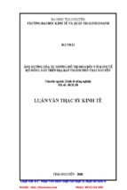
Consider a FG doubly-curved shallow shell (Figure 2.1) of constan thickness (h), the middle
surface is x-y surface, and the z axis is perpendicular to the mid-surface. The projection of shell in
x-y plane is the rectangle with the dimensions in the x and y directions, a and b respectively; The
principal radii of shell in the x and y directions are Rx and Ry, respectively.
y
z
MÆt trung b×nh
x
b
Ry
a
Rx
Figure 2.1. Geometrical shape and dimensions of FG doubly-curved
shell 2.3. The assumptions
The FG doubly-curved shell considered in this thesis is an open shell; the projection of shell in x-y
plane is a rectangular shape that satisfies Mindlin's assumptions.
load.
The steady heat conduction is considered. Therefore, the thermal load is considered as static
The FG shells are subjected to transverse uniformly distributed mechanical load.
3
t
mu
c
t
t
x
The structure is firstly subjected to static mechanical and temperature loads, then the dynamic load are
applied.
The linear analysis is applied, so the displacements of the shell subjected to mechanical load and
thermal load can be written as:
u p u t ud
Thus, the temperature is not only causes the change of the mechanical properties of the
materials (E, ν) but also causes deformation and static initial stress. After deformation, the shell will
be oscillated about the new equilibrium position. To investigate the effect of temperature
distribution on the behavior of shells, the thesis proceeds with the following steps:
- Step 1: Analyze static problems when the shell is subjected to the thermal load and the other
static loads to predict the deflection and stress of the shell.
- Step 2: Stress calculated from the above static problem is considered as the pre-stress of the
shell when the shell oscillates. These pre-stressed components will therefore be taken into account
when setting the dynamic problem equation of the shell.
2.4. Static analysis of FG doubly-curved shells in thermal environment
In this section, the first-order shear deformation Reissner-Mindlin theory is used to establish
the constitutive equations for FG doubly-curved shells subjected to static mechanical loads and
thermal load. The displacement components, and static stress ut , t are determined.
2.4.1. Displacement field
Based on the first order shear deformation theory, the displacement field of the doublycurved shells is assumed as [88]:
x, y, z, t u0t x, y, t zxt x, y, t
tt
v x, y, z, t v x, y, t x, y, t
t
u
tt
(2.2)
t z
0
w
tt
x, y, z, t
y
t
w0 x, y, t
2.4.2. Strain field
Nonzero strain components developed from the displacement field given in Eq. (2.2) are
given as:
(2.3)
with mut is the membrane - bending strains:
u
wt
t
0
t
xx
mu
t
x
t
v
t
yy
t
xy
0
y
0
Rx
t
w
R
t
x
y
y
t
xt
0 y z
t
y
x
t
0 xy
t
y
t
(2.4)
xy
wt vt yt
yRy
t
t
u0
w0
t
x R x
0t
x
0
xz
y
0
is the shear strains:
t
t t
u
v
y
x
c
0
z
t
t yz
0
and ct
0
x
(2.5)
4
2.4.3. Stress field
For FG doubly-curved shells in thermal environment, the constitutive relations can be written as
t
Q
xx
t
Q
yy
t
0
0
t
xz
0
0
0
Q
0
0
0
Q
0
0
0
22
66
44
0
t
yz
0
0
12
12
xy
Q
Q
11
T ( z )
xx
T(z
)
yy
0
0
0
0 t
xxt
0 yy
0 t
t
0
xz
Q
t
xy
55
yz
(2.7)
2.4.4. Internal force resultants
t
The stress resultants are expressed in the form:
N
N xxt
yy
Nt
xy
A
A
11
21A
0
t
A
22
0
B
12
B
B
M xx
0
B
0
A
B
12
11
M t B
yy 21
M xyt 0
t 0
Q
xz
Q
0
22
0
0
0
66
0
0
B
66
0
0
B
11
21
B
22
0
D
11
D
0
D
12
D
0
0
0
0
0
0
21
0
0
0
B
0
0
0
0
0
A
12
22
66
0
0
D
66
0
0
0
t
0x
0
yz
yy
0
0 t
nd
M
0
xy
xx
0
t
x
nd
M
yy
0 t
0
y
0 xyt 0
0
t
0
xz
A t
44
0
t
t
N nd
xxNnd
55
2.4.5. Equations of motion
0y
(2.14)
yz
The principle of minimum total potental energy is used to derive the equatons of moton of
FG doubly-curved shells. The principle can be stated in mathematical form as:
t
t
(2.15)
L U W 0
t
in which: Lt , U t , W t
are variations of the strain energy, of the potential energy of the
external loads, and of the kinetic energy respectively.
Substituting the equations expressed strain energy, potential energy of the external loads,
kinetic energy in to Eq. (2.15). Using the generalized displacement–strain relations and stress–strain
relations, and the fundamentals of calculus of variations and collecting the coefficients of u0t ,
v0t , w0t , xt , yt , the equations of motion of FG doubly-curved shells are obtained as:
u0t :
N t Nxyt Qt 0 ;
x
y
R
xx
t
v
xz
0
x
Qxz Qyzt Nxxt N yyt t
q
x
y
Rx
Ry
t
M
M t
t
0
t
w0t
:
yt :
xy
x
yy
y
Q
yz
z
x
:
N t
xy
N t
x
t
xx
M xy
x
yz
0
Ry
y
t
M
:
yy
Qt
t
Qxzt 0
(2.18)
y
0
Now Eq. (2.3) is substituted into Eq. (2.14) to obtain internal force resultants in terms of
kinematic displacements, which is further substituted in Eq. (2.18) to give the equations of motion in
term of displacements and rotations ut u0t , v0t , w0t , xt , yt .
2.4.6. Analytical solution
The analytical solutions for the present formulation are developed for different boundary
condition. Three following common boundary conditions are considered:
Simply uppor SSSS:
t
v w
0
t t
0
ut
y
wt t
0
5
t
t
N M 0 at x = 0, a
xx
(2.20)
xx
N M t 0 at y = 0, b
t
0
x
yy
yy
Simply uppor Clmp Simply uppor Clmp SCSC :
v t t N t M t 0 at x = 0, a
wt
0
0
t
u v
t
0
0
y
xx
at y = 0, b
t
wt t
0
0
(2.21)
xx
x
y
Clmp CCCC :
t
t
u t v w t 0 at x = 0, a and y = 0, b
(2.22)
t
0
0
0
x
y
SSSS
SCSC
CCCC
Fig. 2.4. Three common boundary conditions
The displacement fields satisfying the boundary conditions in terms of undetermined
coefficients (U t , V t , W t , t , t
) and trigonometric functions are assumed as [69]:
mn
t
t
mn
mn
X m x
Xmn
Ymn
t
t
u0 x, y
Umn
x
m 1 n 1
t
t
w0 x, y Wmn X m xYn y ; x
t
m 1 n 1
t
y x, y Ymn X m
x
Yn y
Yn y ; v0 x, y Vmn X m
x
m 1 n 1
X m
t
t
x
x, y
x
m 1 n 1
Yn y
Xmn
y
Yn y ;
(2.23)
y
m 1 n 1
The assumed trigonometric functions X m x and Yn y functions satisfying the boundary
conditions are broadly classified as SSSS, SCSC, and CCCC as listed in Table 2.1 [69].
Transverse load and thermal load are also expanded in the form of Fourier series as follows:
sin lm xsin n y ; T z
t
q x, y
Qmnt
mn
Tmn z sin lm xsin n y
(2.24)
m 1 n
1
in which
m 1 n 1
0 m
n
4 a
x, si l x si y dxdy ;
Q 0
bq
ab
y n
n
a b
T z si l x si y dxdy
T z 4
n
n
n
mn
m
ab
t
0
0
(2.25)
By substituting equations (2.23) and (2.24) into the equations of motion
in term of
displacements. Applying the Galerkin method, we obtained the system of algebraic equatons for
different boundary conditions in the following form:
(U t
mn
mn
K t
ch
F
t
nd
F
(2.27)
Solve the system of equations (2.27) with m, n
= 1, 2..., the five unknowns
t
t
t
t
, V , W , , ) are determined. Replacing these quantities into the Eq. (2.23), we get
mn
mn
Xmn
Ymn
the displacement components ( ut , vt , wt , t , t ) .
0
0
0
x
y
6
2.5. Dynamic analysis of FGM doubly-curved shell in thermal environment
From above mentioned, the displacements of the shell can be expressed in the form:
p
u u t ud . Static displacement of the shell is determined through solving static problem. Now,
the equations of motion are developed and are solved to analyze dynamic response of the panel in
the thermal environment according to the second approach (Type 2). According to this approach,
stress components caused by temperature have been calculated in Section 2.4 and are considered as
initial stresses when developing the equations of motion of the shell.
Hamilton’s principle is used herein to derive the equations of motion appropriate to the
displacement field and the constitutive equations. The principle can be stated in analytical form as:
T
(2.33)
Ld dt T
T d d W d dt 0
0
d
d
0
0
where U U
in which U d is the strain energy due to additional stresses caused by dynamic loads.
U0 is the strain energy due to inital stress and can be writen as:
U
0
h2
h 2
1
0
d
2
d
w0
0
1
d
w0 w0
0
d
w0
2
dzdxdy
(2.36)
xx
xy
yy
2 x
2 y
x y
in which xx0 , 0yy , xy0 are stress components caused by thermal and static loads.
A
The work done by the external forces is calculated as the formula (2.17) in which dynamic load
is considered as the applied load. The kinetic energy is determined through the time derivatives of the
displacement and density of the material. Determining the equations of total strain energy. External
work, and kinetic energy into Eq. (2.33), using the generalized displacement–strain relations, stress–
strain relations, and the fundamentals of calculus of variations and collecting the coefficients
of u0d , v0d , w0d , xd , dy , the equations of motion are obtained as
N d
d
d
xx
x
Nxy
d
2 ud
Q
Nxy
I
xz
y
R
N
Qyzd
0
x
x
1
t
2
2yd
2 v d
I
I
t 2
0
d
yy
2 d
0
I
1
x
R
0 t 2
t 2
y
Qxzd Qyzd Nxxd N yyd N 0 2 w0d 2N 0 w0d w0d N 0 2 w0d qd
I z
xy
x
R
Ry
xx x 2
x y
yy y 2
y
y
x
M
xx
xy
Qd
x
y
M
M
xy
d
d
yy
I
0
1
I
t 2
2
2 d
y
yz
I
0
1
t
t 2
2yd
v
Qd
t 2
x
d
x
xz
0
2d
2 ud
M
d
2 w 0 d
I
2
2
(2.38)
t 2
Substituting the displacement fields satisfying the boundary conditions in terms of
undetermined coefficients (U d , V d , W d , d , d ) and trigonometric functions assumed in
mn
mn
mn
Xmn
Ymn
similar form as (2.23). Applying the Galerkin method (similar to the one presented in the statc
problem), from equation (2.38), we obtain the system of equations in the brief form as follows:
mn
M d
K
K
ini
mn
d
ch
F d( t )
with Kini is the stiffness matrix caused by initial stress.
2.5.1. Free vibration analysis
(2.45)
7
From equaton (2.45), set the load vector equal to zero, we get the equaton of the FG doubly-
curved shallow shells
free-vibration analysis. SetU mnd t U
for
mn
Wmnd t Wmn0 ei
t
t Xmn0 ei t ; Ymnd t
; Xmnd
Ymn
0
ei
t
0
d
0 i t
eit ; Vmn t Vmn e ;
we have the equations of free vibration
problem which can be written as standard eigenvalue matrix, with 5 unknown displacements
mn0 Umn0 , Vmn0 , Wmn0 , Xmn0 , Ymn0 as follows: mn
ini
K
K 2 M 0
0
(2.51)
The natural frequency of shell is determined from the equation:
de K
t
ini
K
2 M
0
(2.52)
Solve eigenvalue equations (2.52) we obtain natural frequencies mn ; the fundamental
natural frequency is predicted by cb min mn .
2.5.2. Forced vibration analysis
The equation (2.45) is the forced vibration equation of FG doubly-curved shallow shells in
thermal environment without damping. Effect of temperature and other static loads which considered in
the static problem are expressed through the stiffness matrix [K ini]. Therefore, the right side of the
equation is dynamic load vector only.
When taking into account the damp, the equation (2.45) becomes:
(2.54)
M d C d K K d F d t
mn
where [C] is damping matrix [98]:
mn
2
C a M aK K
1
ini
mn
ini
(2.55)
in which a1 and a2 are mass damping factors and Rayleigh damping factors, respectively.
Using the Newmark- integral method to solve the system of equations (2.54) obtained the
time-shifting response of the FG doubly-curved shallow shells subjected to mechanical loads in the
thermal environment.
2.7. Validation examples of analytical solution
Based on the present formulation, three Matlab’s codes for PC are built, including:
ShellpanelStatic(GT) program: predict deflection and stress of the FG doubly-curved shallow
shells subjected to mechanical loads in the thermal environment.
ShellpanelStatic(GT) program: determinate natural frequency and vibration mode of FG doublycurved shallow shells in the thermal environment.
ShellpanelForcedvibration(GT) program: investigate dynamic response of FG doubly-curved
shallow shells in the thermal environment.
The above mentioned programs are implemented in steps as shown on the flowchart in
Figure 2.6, Figure 2.7 and Figure 2.8 in the thesis.
Thus, in this chapter, the constituve relations, the equations of motion are summarized for
the FG doubly-curved shells in thermal environment based on the first-order shear deformation
theory. Using Galerkin method and Newmark method, analytical solutions are developed to
calculate deflection, stress, natural frequency, and to analyze dynamic response for doubly curved
FG shell in thermal environment with various common boundary conditions.
Computer programs have been built for numerical investigations. However, the limits of the
analytical solutions can be pointed as following:
- It is only applicable for some simple types of curved shell structure such as cylindrical
shell, spherical shell and hyperbolic paraboloid shell.
- It is only applicable for few common boundary conditions.
The goal of chapter 3 is developing finite element model for static and dynamic analysis of
FGM shells with different shapes in thermal environment. The finite element model will overcome
the limitations of the analytical model.
8
function of the form
Publications related to the contents of this chapter, including: (1), (2), (3), (4), (5), (6), (7)
(in "List papers of the author related to the thesis topic").
CHAPTER 3
STATIC AND VIBRATION ANALYSIS OF FGM SHELL IN THERMAL ENVIRONMENT
USING FINITE ELEMENT METHOD (FEM)
3.1. Introduction
In Chapter 2, the analytical solutions have been presented to analyze static and dynamic
response of the FG doubly-curved shells in thermal environment. However, the analytical solution
is only applicable for the doubly-curved shell structures with some simple boundary conditions. To
overcome this limitation, in this chapter using degenerate 3D shell elements based on Mindlin’s
theory, the finite element model is developed for static and dynamic analysis of FGM shells.
3.2. Geometrical shape of FGM shell
Considering the FGM shell with a
surface shape described by a mathematical z f x, y , the projection
of shell in plane x-y is a rectangle with the
length a and witdth b, the shell has a constant
thickness h as shown in Figure 3.1.
Figure 3.1. Co-ordinates system of a FG shell
panels
3.3. Select the type of element
Finite element method has many types of elements that can be used to model plate and shell
structures. In this thesis, the degenerate 3D shell elements (Figure 3.2) are used to model FGM
shell structures with various shapes. The advantage of this shell elements is that it allows to
approximate simulation of real shell structure, the number of degrees of freedom is significantly
reduced by removing nodes on the top and bottom, the calculation is only depends on the degrees of
freedom of the nodes in the middle surface.
3.4. The degenerate 3D shell elements
As shown in Figure 3.2, the degenerate 3D
elements are reductions from the 3D element to
the flat element with the addition of directional
vectors at each node.
Figure 3.2. The degenerate 3D shell elements
3.5. Finite element model of FGM shell using the degenerate 3D shell element
3.5.1. Degenerate 3D shell element
From the 3D element, the degenerate 3D shell element is constructed by removing nodes on
the top and bottom and keeping only nodes at the reference surface (usually the middle surface). In
addition, at the nodes on the reference surface, a node coordinate system V1V2V3 is added, in which
the vector V3 is a directional thickness vector and is calculated through the coordinates of the upper
9
and lower surfaces of the 3D element. As shows in the above mentoned coordinate system, the fnite element mesh
must be implemented as using 3D element.
In this thesis, we propose a way to determine the node coordinate system proposed by the
F x, y,z z f x, y 0 , it
function which represents the surface of shell z f x, y
is
easy to obtain the normal vector at any point K xK , yK on the shell surface as follows:
V 3K
x
K
K
K
y
F x ,y
K
,1 T
,F x , y
(3.7)
with
(3.8)
F ; F
F
F
x
y
x
y
The normal unit vector at the point is defined
1
l3
K
v3
Fx xK , yK
3
Fy xK
m3
n
Fx2 xK , yK Fy2 xK , yK 1
, y K
1
(3.9)
After determining vectorV3 , the vectors V1 and V2 are also determined. By this way, the
meshing becomes easier and the model can be applied with the shells which the surface
mathematical function has the form: z f x, y .
3.5.2. Displacement field
The coordinates of any point in the element are defined:
x
y
x0i
8
8
h
N i , y0i Ni ,
z
2
l3i
m
3i
(3.10)
z i 1
n
0i
3i
According to the Mindlin’s assumption, the displacements of any point in the element are
defined as follows:
i 1
u0i
u
8
where
l
1i
m
1i
1i
T
l
2i
m
1i
m
xi
and l
2i
0i
m
2i
n
2i
1i
(3.11)
v0i n
n
yi
2
1i
2i
are
cosine
directions
of two vectors V1 , V2 as
w
i 1
n
v N i
,
w
h l
T
2i
defined in section 3.5.1; xi , yi are the rotations of the normal segment.
Equation (3.11) can be rewritten as:
u
v
8
N Ai NBi ui
w i 1
3.5.3. Strain field
(3.12)
The strain components in the element coordinate system are obtained from the derivative of
the corresponding displacement components as follows:
10
u
'
x'
x'
v'
y'
y'
' x' y' u'
v'
x' z '
y'
x'
y' z '
u w'
'
z
'
v'
z
'
(3.16)
x'
w'
y'
These components can also be calculated in the general coordinate system through the following transfer
matrix:
u
'
x
'
v
y
'
x'
y'
'
x
y
u'
x
v
y
v'
y'
x' y'
u
T
x y
u
T
v
T
(3.25)
x'
y
x
v' w'
v w
y' z '
yz
z'
x' z '
y'
xz
z
y
w u'
u
'
w
x' z'
z
x
These strain components can be represented and calculated
in natural coordinates through
the Jacobean matrix of transformations as follows:
dV dxdydz det J d d d
(3.26)
Combining the Eq. (3.25), (3.30) and (3.31), we get the strain components in the general coordinate system as
follows:
8
where B B1
T
ue
u B ue
Bi i
B2 .
B8 is the deformation properties matrix,
i 1
u1
.
T
u 2T
. . u8T is the node displacement vector of the element.
(3.32)
3.5.4. Stress field
The stress components are calculated through the strain components as described in Eq.
(2.8) and (2.9), which can be written in reduced form as follows:
' D' ' nd
(3.34)
3.5.5. Static analysis of FGM shell
Apply the total potential energy minimization principle to establish a static equilibrium
equation for the FGM shell subjected to mechanical load and thermal load as in Eq. (2.16).
The strain energy of element:
- Xem thêm -