See discussions, stats, and author profiles for this publication at: https://www.researchgate.net/publication/301299009
MATLAB BASED PERFORMANCE REPLICATION
IN HIGH ALTITUDE PLATFORMS (HAPs)
COMMUNICATION SYSTEM
Conference Paper · March 2016
CITATIONS
READS
0
11
1 author:
Fakir Mashuque Alamgir
East West University (Bangladesh)
5 PUBLICATIONS 0 CITATIONS
SEE PROFILE
All in-text references underlined in blue are linked to publications on ResearchGate,
letting you access and read them immediately.
Available from: Fakir Mashuque Alamgir
Retrieved on: 27 September 2016
International Conference on Electrical, Electronics, and Optimization Techniques (ICEEOT) - 2016
MATLAB BASED PERFORMANCE REPLICATION IN
HIGH ALTITUDE PLATFORMS (HAPs)
COMMUNICATION SYSTEM.
B. M. Adnan
Sopan Chakma
East West University
Department of Electrical & Electronic Engineering
Dhaka, Bangladesh
E-mail:
[email protected]
East West University
Department of Electrical & Electronic Engineering
Dhaka, Bangladesh
E-mail:
[email protected]
M. M. Jahazeb Alam
East West University
Department of Electrical & Electronic Engineering
Dhaka, Bangladesh
E-mail:
[email protected];
Abstract— This thesis considers the examination by simulation of
a digital narrow-band communication system for a scenario which
consists of a High-Altitude aeronautical/ spacecraft Platform (HAP)
and fixed/ mobile terrestrial transceivers. The aeronautical channel is
modeled considering geometrical (angle of elevation vs. horizontal
distance of the terrestrial reflectors) and statistical arguments and
under these circumstances a serial concatenated coded digital
transmission is investigated for several assumptions related to
radio-electric coverage areas. Different flaws which can affect the
signal strength are investigated in this particular case. We have
considered specific modulation type (Differential Phase Shift
Keying Model) and three basic channel types to model the
aeronautical channel. Specific Bit Error Rate and Signal to Noise
ratio per bit are considered to evaluate channel performance. The
results indicate a good viability for the communication system
proposed and analyzed.
Keywords— High altitude platforms (HAP’s);Aeronautical channel
model; Angle of elevation; Rice factor; Coverage; Concatenated
communication systems; Differential phase shift keying (DPSK);
Bit error rate; Signal to noise ratio per bit
Ι. INTRODUCTION
When high altitude platform (HAP’s) and terrestrial
transceivers are taken into consideration, possibilities of
point-to-multipoint radio communications emerges. In
abroad, researches about the use of HAP’s for narrow and
broadband communication system is developing [1], [2]. The
performance of these systems for various telecommunications
services-mobile and/or fixed terrestrial surroundings are
considered as an open problem. In terms of digital
transmission theory and looking from its point of view, the
designing of aeronautical channel is an important feature that
978-1-4673-9939-5/16/$31.00 ©2016 IEEE
Fakir Mashuque Alamgir
Senior Lecturer, East West University
Department of Electrical & Electronic Engineering
Dhaka, Bangladesh
E-mail:
[email protected];
needs to be taken into consideration [3], [4], [5]. This paper
mainly focuses and handles the theoretical derivation of a
channel model that links the communication system between
the platform and terrestrial mobile/fixed users and stations.
Analysis of the channel modeling will be done by considering
the geometrical and statistical arguments and the paper
follows this reasoning.
The architecture of HAP´s can be considered as hybrids;
they have some common zones related to terrestrial
communications, particularly Fixed Wireless Access, but are
identical to the satellites when it comes to power limitations
and general network architecture. In a mobile communication
context is the fact it could substitute or support the terrestrial
network, keeping away from problems with environmental
impact and electromagnetic pollution. Platform design has
several restrictions, relating to the applications to achieve:
power available for the payload, stability, and maximum
transmit power of the transmitters, link availability and many
more.
What is HAP?
High Altitude Platforms (HAPs) are quasi-stationary platforms
that are situated in the stratosphere (17-22 Km above from sea
level). It is usually positioned between the active area of the
terrestrial and satellite communication equipments. The
platforms or vehicles are usually solar-powered (power supply
from ground possible) airplanes, airships or balloons. They are
considered to do the work in the role of HAPs. The HAPs and
their applications provide potential benefits. The benefits are
specified in the area of internet multimedia, remote sensing
and navigation system support, military surveillance,
delivering of communications services, etc. The prospects and
promises of applications of HAPs from terrestrial and satellite
broadcasting are much higher. A small delay and undisturbed
line-of-sight link between the customer and base station is one
of the examples. People have been researching, implementing,
developing for civil and military interest and of international
projects for the past few years. As it is found out that this
could be the next revolutionary platform for communication,
so HAPs turn for attention towards it is of greater possibilities.
Day by day interests on aerial platforms are rising. So its
development comes into consideration. The advancement of
technologies has created better, stronger and effective
materials which are UV resistant, leak proof to helium and
long durable. These platforms are capable to travel the desired
area and to make their return path to the world.
Wireless delivery problems can be solved through aerial
platforms. Aerial platforms will carry communications relay
payloads and it will operate in a quasi-stationary position at
altitudes up to some 17 km to 22 km. A payload can act as a
complete base-station using aerial platforms or a transparent
transponder similar to satellites. Line-of-sight propagation
paths can be provided to most users with a modest FSPL, thus
enabling services that take advantage of the best features of
both terrestrial and satellite communications. A single aerial
platform can be a substitute to a large number of terrestrial
masts. With its striking qualities, it can reduce the associated
costs, environmental impact, backhaul constraints, site
allocation problems, etc. Regarding the above factors, HAPs
can be a more beneficial and helpful option for wireless
communications around the globe.
The second chapter presents the scenario about the
analyzation of radio communication system and under these
conditions, the variables/parameters are the major part . The
third chapter reflects on the relationship between
geometrical and statistical aspects related to angle of
elevation vs. Rice coefficient vs. horizontal distance of the
terrestrial reflectors. The fourth chapter reflects on the
concatenated coded digital transmission and simulation
models. Results and conclusions are presented in the chapter
six and seven.
ΙΙ. RADIO ELECTRIC SCENARIO
A.General Aspects
The propagation of radio signals from/to HAP to/from
ground antennae is affected by the aeronautical channel in
several ways, but the most important effect is related to the
multipath phenomena and therefore with the availability of the
radio link. The scenario to consider for this aeronautical
channel may define three areas: an urban zone, a suburban or
opened zone and a rural zone.
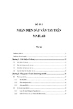
This whole scene will be represented by the figure given in
Figure 1. The scene consists of an airborne which can be a
globe, airplane or a helicopter. The scene also consists of a
transceiver on the ground. In order for the scene to execute
successfully, three aspects must be taken into consideration.
•
•
•
The direct ray or the line of sight could be adjusted
from the deployed platform.
Any changes of elevation angle “α” are able to create
variations in the delays of the received signals. It also
does the same to an increase of the multipath. In
addition to that, the elevation angle depends on the
flight height “h” and horizontal distance “r”. So any
change on “h” and “r” will change “α” and this will
create change in multipath and signals.
The displacement of the receivers which makes the
elevation angle is less than 45 degrees or the less than
half height, it will cause shadows of the order of half
or 50% at the time of connection.
Figure 1. Platform air terminal. (Direct ray and reflected ray or
echo)
In the figure above, the transmitter (Tx) is situated on Ariel
platform or HAP and the receiver (Rx) is situated on the
ground. The figure shows a Line-Of-Sight ray or the direct
ray. The figure also shows a reflected ray in the receiver. So,
in the first approach the reception will consist of two signals.
From the figure, these parameters can be considered:
dLOS = h/ sin(α)
r = h/ tan(α)
r = horizontal distance receiver
Δr = delta r (horizontal distance reflector)
dLOS= Line of Sight distance
deco= Echo distance
B. Echo delay
Echo delay mainly occurs when radio echoes return to the
sender after a couple of seconds of radio transmission. Along
with that, an unexpected second radio echoes with a
significant time delay occurs after the primary radio echo had
ended. The signals may pass the ionosphere and then it will be
deducted in the magnetosphere out to a distance of several
earth radii over to the opposite hemisphere where they will be
reflected on top to the ionosphere. In addition to that, the
2
0.014
80 deg
70 deg
60 deg
0.013
0.012
0.011
Δ FS L dB
round trip time varies with the geomagnetic latitude of the
transmitter. The further the station, the larger the delay. As a
result, echo delay is directly proportional with the
geomagnetic latitude.
The propagation times are proportional to the corresponding
slant ranges plus detours, and then the echo delay (∆τ) may be
formulated as:
0.01
0.009
0.008
2
0.007
-2
10
1.9
-1
0
10
1
10
2
10
3
10
10
h/Δr
1.8
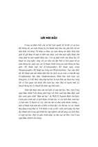
Figure 3. Distortion of amplitude of the echo affecting the
delay power spectrum, ΔFSL dB.
1.7
Δ τ.c /Δ r
1.6
1.5
-3
13
x 10
150 deg
140 deg
130 deg
120 deg
110 deg
100 deg
90 deg
1.4
12
1.3
1.1
1
-2
10
90 deg
45 deg
22.5 deg
11
10
-1
10
0
1
10
10
2
10
3
10
h/Δr
Figure 2. Graph Δ τ ·c/|Δr| v/s h/|Δr|, Echo delay
9
Δ FS L dB
1.2
8
7
C. Amplitude of echo
At the point of view of the radar, it is defined as an empirical
measure of the strength of a target signal as determined from
the appearance of the echo. In addition to that, the amplitude
of the echo is measured by the deflection of the beam.
Distortion of the echo amplitude is considered to be the main
drawback because it generates signal degradation. Signal
degradation causes inter symbol interference and phase noise
at the sampling point. Amplitude distortion is one type of
linear distortion. Linear distortion is considered to be a kind of
impairments when a signal generates poor frequency response.
This distortion affects the delay power system. There is a way
to detect amplitude distortions. It can be done by changing the
amplitude of the desired signal. If the impairments amplitude
relative to the desired signal becomes identical, then the signal
is distorted. As a result, the amplitude of the echo is distorted.
Following the considerations of the equation in the echo delay,
the echo signal can be related to the Free Space Loss (FSL) by
the formula:
6
5
4
-2
10
-1
10
0
1
10
10
2
10
3
10
h/Δr
Figure 4. Distortion of amplitude of the echoes taking range
from 90° to 150°
ΙΙΙ. GEOMETRICAL-STATISTICAL RELATIONSHIP CHANNEL
The characterization is mainly distributed into two parts. One
is Geometric Characterization and the other is Statistical
Characterization.
A. Geometrical Characterization
From the geometrical point of view, in order to enhance or
develop the channel model, there must be a good
approximation of both the physical dimension and the type of
environment where the system is located. The physical
characteristics, mainly play a vital role when it comes to
channel quality. There is a strong relationship between the
receiver’s location on Earth and the HAPs and the channel
characterization. The HAPs are placed in a good quasistationary condition at an altitude of around 20-25 km and the
whole geometrical characteristics are specifically shown in the
figure given below
3
Figure 5. HAPs based system geometry
In the above figure, the parameters are
α: User angle elevation in degrees
h: Platform height in meters
r: Horizontal distance receiver
After certain precise calculation, it is found out that the best
possible channel quality for elevation angles must be around
30° to 90° ( provided in a specific area), and this is where the
control and gateway ground stations needs to be located.
B. Statistical Characterization
For the development and improvement of the channel models
for HAP based systems, Geometrical and Statistical
parameters are surely needed. If a user is located just below
the platform i.e elevation angle is close to 90° then the channel
is assumed to be Gaussian with very large values of the Rice
factor (K>20). As the elevation angle decreases to a certain
value, the channel can be modeled using a Rice distribution
with smaller K values.
From a statistical point of view, the amplitude probability
density is mathematically expressed as:
Figure 6. Rice Coefficient K in function of the angle of
elevation (α) and horizontal distance of the reflectors (Δr,
delta r). [8]
Then : [8]
α →90°⇒K→ ∞ Gaussian Channel
α → [12°<α<90°] ⇒Rice Channel
α <12° ⇒ K→ 0, Rayleigh Channel
ΙV. COMMUNICATION SYSTEM SIMULATION MODEL
The communication system simulation model is mainly used
to understand the effects of the aeronautical channel and
mainly to bridge the gap between the communication systems
of the platform and a fixed/mobile terrestrial receiver. Below a
simulation model is provided for further clarity. It is used for
modeling and simulation of both proposed and actual
spacecraft communication systems.
Here,
is defined as amplitude direct ray and Io is the
Bessel function of first type and order zero.
The rice distribution factor, K, can be mathematically
expressed as:
K can also be formulated as from a geometrical point of view:
Here, “a” is related to the direct ray:
dLOS = h/ sin(α)
and “c” is related as the reflected ray:
Relating all the information, an equation can be generated
The following figure 6 indicates this relationship
Figure 7. Generic Spacecraft Communication System
Simulation model of the channel.
From the above generic spacecraft communication system
simulation model of the channel we can write an equation
which is given below:
ỹ(t)=ñ(t)+(x(̃ t)*K(α))+(x(̃ t)*g̃(t))
Here, x̃(t) is defined as the complex envelope of the serial
concatenated coded signal. The complex envelope mainly
creates an analytical signal from a signal that contains no
4
imaginary component.The analytical signal is a complexvalued function that contains no negative frequency
components. The serial concatenated coded signal is used to
encode the transmission of data over a noisy channel.
Encoding of data can be done by putting a sequence of
characters in a specialized format for efficient transmission or
storage. Overall, the task of x̃(t) is to shift the frequency of the
analytical signal as well as the serial concatenated coded
signal.
Then comes g̃(t), which is defined as the unitary power fading
process. It arises when there is a deviation of the attenuation
affecting a signal over certain propagation media. The fading
process occurs due to multipath scattering effects, time
dispersion, which all arises due to the relative motion between
the transmitter and the receiver.
simulates the system, BERTool iterates over the choice of
Eb/N0 values and collects the results.
• Plots one or more BER data sets on a single set of axes. For
example, one can graphically compare simulation data with
theoretical results or simulation data from a series of similar
models of a communication system.
• Fits a curve to a set of simulation data.
• Sends BER data to the MATLAB workspace or to a file for
any further processing one might want to perform.
Then it is K(α), which mainly multiplicates function which
allows the whole signal to vary the ratio between the average
powers of the line of sight and diffuse signals. Here, line of
sight is mainly a type of propagation that can transmit and
receive data when the transmitter and the receiver are in face
to face with each other without any obstacles present between
them. Diffuse signals mainly occur due to interference or
obstacles. The overall ratio mainly defines K(α).
BER= (Bits in Error) / (Total bits received)
Finally comes ñ(t), which represents the white noise process.
A white noise process is one with a mean zero and no
correlation between its values at different times. It mainly
approximates noises in practical situations.
Then ỹ(t) is the desired signal which is recovered from the
noise and other fading process.
V. SIMULATION TOOL, MODULATION TYPE AND CHANNEL
MODEL
A. Simulation Tool: BERTool [12]
BERTool is a command in MATLAB platform that launches
the Bit Error Rate Analysis Tool (BERTool) application.
This application is capable to analyze the bit error rate (BER)
performance of communications systems. It calculates the
BER as a function of signal-to-noise ratio. It evaluates
performance either with Monte-Carlo simulations of
MATLAB functions and Simulink models or with theoretical
closed-form expressions for selected kinds of communication
systems.
Using BERTool one can:
• BER data generated for a communication system
• Closed-form expressions for theoretical BER performance of
selected types of communication systems.
• The semianalytic technique.
• Simulations contained in MATLAB simulation functions or
Simulink models. After creating a function or model that
1. Bit Error Rate (BER)
The Bit Error Rate (BER) or quality of the digital link is
measured using the number of bits received in error divided by
the transmitted number of bits.
In digital transmission, the number of bit errors is the number
of receiving bits of a data stream over a communication
channel that has been altered due to noise, interference,
distortion or bit synchronization errors. The BER is the
number of bit errors divided by the total number of bits
transmitted in a particular time interval. BER has no unit as
it’s a ratio for measuring the performance and usually
expressed as a percentage. For instance, N number of
erroneous bits out of 100000 bits transmitted would be
expressed as N*10^-5. In this paper, we assume that one
erroneous bit out of 100000 bits would be transmitted. That is,
the bit error rate is 1*10^-5. As we know even 1% BER is too
much higher so it is always trying to keep it as low as
possible, for this case we also followed this issue. In this case
we have taken 100000 bits out of which only 1 bit is error
which is .001% error. That means it is acceptable as it is very
much lower than 1% BER.
2. Signal to Noise Ratio (SNR)
The ratio between the received signal strength over the noise
strength in the frequency range of the operation is known as
Signal to Noise Ratio (SNR). For the physical layer of Local
Area Wireless Network (LAWN) it is a vital parameter.
Usually noise strength, able to include the noise in the
environment and other unwanted signals (interference). BER
is inversely linked to SNR that is high BER causes low SNR
and vice versa. However, high BER is the reason that
increases packet loss, increase in delay and decreases
throughout. In the multichannel environment the actual
relationship between BER and SNR is not easy to determine.
Signal to noise ratio (SNR) is an index that generally used to
test the quality of a communication link. It is measured in
decibels (dB) and the expression is given below:
SNR = 10 log10 (Signal Power / Noise Power) dB
SNR tests the quality of a transmission over a network
channel. The greater the signal to noise ratio, the easier it is to
5
identify and subsequently isolate and eliminate the source of
noise. If the value of SNR is zero, then it means that the
expected signal is virtually indistinguishable from the noise
signal. In this paper, we have examined different fading
channels according to SNR with the constant bit error rate, for
our case that is 10^-5.
B. Modulation Type: Differential Phase Shift Keying(DPSK)
Differential phase shift keying (DPSK), is one kind of phase
shift keying (PSK) or general type of phase modulation that
transmits or transfers data by changing the phase of carrier
signals/waves. As we know in Phase shift keying (PSK), only
one cycle is contained by High state, however DPSK contains
one and half cycle. Differential Phase Shift Keying (DPSK) is
such type of modulation system or technique which codes
information using the phase difference between two close
neighboring symbols. So, each symbol in the transmitter is
modulated relative to the immediate prior symbol and
modulating signal, for example, in Binary Phase Shift Keying
(BPSK), where 0 and 1 represent “no change” and “+180
degrees” respectively. Again in the receiver, the current
symbol is demodulated, where the previous symbol used as a
reference. The previous symbol serves as an estimate of the
channel. A no change condition causes the modulated signal to
remain at the same 0 or 1 state of the previous symbol.
Usually this modulation system is 3dB poorer than coherent
based on theoretical measurement. The reason behind this
poorness because the differential system has 2 sources of
error: one is corrupted symbol, and another one is corrupted
reference.
In DPSK, usually in the transmitter where each symbol is
modulated relative to the phase of the immediately preceding
signal component and then the data being transmitted. Usually
DPSK is expressed as M-DPSK where M is the number of
modulation order such as M = 2, 4, 6…. [11]
Different channels can be assembled perfectly as the
performance and the design of the channels depend upon the
precision of the simulation. Fading is the very influential
factor in the wireless communication system as it indicates
about the fading formats in different conditions. No model can
tell about the environment. A chosen signal should be error
free, or very close to error free. The quality of voice and data
transmission depend on the error of the signal. Selecting the
fading model is the main factor while development of the
application. The examination depending on the DPSK will
provide the idea which helps in the application development in
the market. Mainly three basic fading channel models are
considered here, they are: Additive White Gaussian Noise
(AWGN), Line of Sight (Rician) and Non Line of Sight
(Rayleigh) Fading Channel models.
1. Rayleigh Fading Channel
Non Line of Sight fading or Rayleigh fading occurs due to the
multilink reception. The effect of the environment spreads to a
wider area on a radio signal in this model. This one is the
cheapest model of the signal propagation (i.e. For ionosphere
and troposphere). This model is most relevant while there is
no dominant propagation between transmitter and receiver. If
the channel signal response is modeled as a Gaussian process
with respect to the distribution of the individual elements and
if the process has zero mean and phase lie between 0 to 2π
radians, then the equation of probability density function is:
2. Rician Fading Channel
Line of Sight or Rician Fading model is a part of Rayleigh
fading, but it has a strong line of sight path in the Rayleigh
fading environment. In satellite communications and for some
urban scenarios this fading model is acceptable and applicable.
This fading model is considered as small-scale fading due to
the probability of deep fades is lower than that in the
Rayleigh-fading model. The mathematical expression of
probability density function of the amplitude (which also a
Rician distribution) is:
3. Additive White Gaussian Noise Channel
Figure 8. Block Diagram of DPSK Modulation.
C. Channel Model
Now-a-days wireless communication is one of the most
important communication systems, which is also vastly used
in the technology development and improvement areas.
Additive White Gaussian Noise (AWGN) is used when the
Doppler Effect occurs between a moving source and stationary
receiver. To model the received signal at the antenna arrays
narrowband data model is used. It assumes that the enclosure
of the signal wave front inseminating across the antenna array
usually leftovers constant. This model is applicable for the
signals which have bandwidth much smaller than the carrier
6
frequency. As per above assumption or hypothesis, the
received signal can be written as:
H(t) = A(Ө)b(t) + N(t)
Where, A(Ө) is the array manifold vector and N(t) is AWGN
with zero mean and two-sided power spectral density given by
No/2.
From the above table, we can see that AWGN channel
provides 10dB SNR for 10^-5 Bit Error Rate, on the other
hand Rayleigh channel provides the >20dB SNR for the same
BER, while Rician channel provides different SNR for
different values of K for same BER.
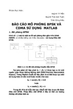
Result Graph 2:
0
VΙ. RESULT ANALYSIS
10
Result Graph 01:
0
10
AWGN
Rayleigh
K=10
K=15
K=20
K=25
K=35
-1
10
-1
10
-2
10
BER
To evaluate the performance simulation we used a source of
32 Kb/s along with the concatenated coding (R-S, interleaving
and convolution codes). We used a special tool in MATLAB
named “BER TOOL” to get the output where we used above
instructions to find the output. This information protected by
this FEC modulates a DPSK and is transmitted over an
aeronautical channel. We used several values of “K” to
evaluate the performance simulation. Again, we measured the
received data considering in Bit error rate (BER) vs. signal to
noise ratio per bit (Eb/No). For several circumstances the
results are presented in the figure 9 and 10
A1 DPSK,Uncoded,ch.Rayleigh
A2 DPSK,Uncoded,ch.Rayleigh (higher order)
B1 DPSK, Uncoded, ch. AWGN
B2 DPSK, Convolutional coded (Hard), ch. AWGN
B3 DPSK, Convolutional coded (Soft), ch. AWGN
B4 DPSK, Reed-Solomon coded, ch. AWGN
-3
10
-4
10
0
5
10
15
Eb/N0 (dB)
20
25
30
Figure 10. Channel codifications: A1, A2 worse case uncoded
Rayleigh Channel; B1 uncoded better case, Gaussian channel;
B2, B3, B4 concatenated coding better case, Gaussian
channel.
From the graph, A1, A2 curve shows that the analytical bound
for worst case (Uncoded Rayleigh channel with angle
o
o
elevations in the 0 -12 degrees range, with height, h=25 km).
Therefore B1and B4 curves (encoded and RS coded
respectively) better case Gaussian channel (channel with angle
-2
BER
10
o
o
elevations in the 50 -90 degrees range). Again B2, B3 curves
(convolutional coded hard and soft decision respectively, with
Gaussian channel) also showing better channel with
concatenated coding.
-3
10
-4
10
0
2
4
6
8
10
Eb/N0 (dB)
12
14
16
18
20
Figure 9: Platform channel v/s angle of elevation modulations
DPSK. Gain Rice K(α).
From the figure we can see that the AWGN channel provides
the low SNR where Rayleigh channel provides the worst that
means highest SNR. Therefore Rician channel provides the in
between SNR for different values of K.
Table Ι. BER vs. SNR Comparison for AWGN, Rayleigh and
Rician Channel with Gain Rice K (α)
BER
AWGN
Rician (SNR
Rayleigh
(SNR (dB))
(dB))
(SNR (dB))
10^-5
10.5
18.9 (K=10)
> 20
10^-5
-
13.1 (K=20)
-
10^-5
-
11.9 (K=35)
-
Table ΙΙ. BER vs. SNR Comparison for AWGN and Rayleigh
Channel with (Coded and uncoded)
BER
Rayleigh
Gausian
Gausian
Channel
Channel
Channel
(Uncoded)
(Uncoded)
(concatenated
[SNR(dB)]
coded)
[SNR(dB)]
[SNR(dB)]
10^-5
26.5
10.2
8
(Convolutional,
Hard)
10^-5
16 (higher
4.5
order)
(Convolutional,
Soft)
10^-5
10.5 (RS
coded)
From the above table, we can see that included Rayleigh
channel provides higher SNR, which is around 26.5 dB than
both coded and uncoded Gaussian channels. However, this
channel provides lower SNR 16 dB for higher modulation
7
order of 4 and higher diversity order of 6, but both cases is not
better than a Gaussian channel. On the other hand, both coded
and uncoded Gaussian channels provide very lower SNR than
a Rayleigh channel. For instance uncoded Gaussian channel
provides 10.2 dB, convolutional coded, hard provides 8dB,
convolutional coded, soft provides 4.5 dB, and RS coded
provides 10.5dB which are way better than a Rayleigh
channel. Here one thing needs to remember that all SNR are
found against 10^-5 BER.
VΙΙ. CONCLUSION
[4] Peter Hoeher, Axel Jahn, Hermann Bischl, ”On Satellite
Emulation by an Airborne Platform, Institute
for
Communications
Technology(DLR)
Global
Telecommunications Conference, 1996. GLOBECOM '96.
'Communications: The Key to Global Prosperity , Volume: 2
, 1996 Page(s): 995-1000 vol.2 IEEE,1996.
[5] Axel Jahn, Hermann Bischl, ”Channel Characterisation
for Spread Spectrum Satellite Communications”, Proc. IEEE
Int.
Symp.
On
Spread
SpectrumTechn.
And
Appl.,Mainz,Germany,Sept.1996.
In this paper, a geometrical-statistical channel model is used.
Communication System Simulation Model is used to analyze
the different outcomes which can affect the signals of HAPs.
Based on the Communication System Simulation Model
different graphs are generated which can indicate the
distortions and other flaws that can affect the performance of
HAPs Communication Systems. It is seen that Gaussian
channel always provides less signal to noise ratio whether it is
coded or uncoded for the same modulation order, the same
modulation system as well. On the other hand Rayleigh
channel provides the poor output, which is higher signal to
noise ratio. So, the proposed communication system has a
good feasibility of implementation with Gaussian channel.
The Communication System Simulation Model was further
analyzed in several circumstances following authors
referenced and the overall results were precise and accurate
and provided a good feasibility for the proposed
communication system.
[6] J.A.Delgado-Penín, H.Carrasco, F. Ulloa-Vasquez,
E.Bertran, ”Space- Time coding and processing to improve
radio communication coverage from High Altitude Platforms
(HAPs)-An
approach”,
DASIA
2001
–SP483,Niza,France.ESA Publication, ISBN 92-9092-773-9
References
[10]http://www.nasa.gov/centers/goddard/news/student_balloo
n.html
[1] G.
Djuknic,
Lucent
Technologies,
"Wireless
Communications Services via High-Altitude Aeronautical
Platforms", IEEE Communications Magazine , Sep 1997, pp.
128-135.
[2] D. Grace,
N. E. Daly, T.C. Tozer, A.G. Burr,
”LMDS from High Altitude Aeronautical Platform”, in
IEEE Globecom´99, December 1999.
[3] P. Hoeher , E. Haas, "Aeronautical Channel Modelling at
VHF-Band", Institute for Communications Technology,
Germany Aerospace Center, IEEE, Veh. Techn. Conf., vol.
4, 1999, pp.1961-1966
[7] T. C. Tozer and D. Grace : ‘High-altitude platforms for
wireless communications’ from ELECTRONICS &
COMMUNICATION ENGINEERING JOURNAL JUNE
2001.
[8]
Ulloa-Vasquez,
Fernando;
Delgado-Penin,
J.A
‘Performance simulation in High Altitude Platform (HAPs)
communication system. ‘Proceedings of DASIA 2002,13-16
May 2002, Dublin, Ireland. Ed: R.A Harris . ESA SP-509,
Noordwijk, Netherlands: ESA Publications Division, ISBN
92-9092-819-0, 2002, id.48.1-48.9, published on CD-ROM,
Session 8B
[9] Google loon project
[11] Deepak K. Chy, Md. Khaliluzzaman. Evaluation of SNR
for AWGN, Rayleigh and Rician Fading Channels Under
DPSK Modulation Scheme with Constant BER. International
Journal of Wireless Communications and Mobile Computing.
Vol. 3, No. 1, 2015, pp. 7-12.
doi: 10.11648/j.wcmc.20150301.12
[12] MATLAB Communications Toolbox “BERTool: A Bit
Error Rate Analysis GUI”
[13] Karapantazis, S; Pavlidou, F ‘Broadband communication
via high-altitude platforms: A survey’ Communications
Surveys & Tutorials, IEEE; Year:2005; Volume:7, Issue:1
[14]http://www.ralfwoelfle.de/elektrosmog/redir.htm?http://w
ww.ralf- woelfle.de/elektrosmog/ technik/haps.htm
8