Evaluating QoS Parameters for IPTV
Distribution in Heterogeneous Networks
Ioan Sorin COMSA*, Radu ARSINTE**
Abstract—The present work presents an architecture
developed to evaluate the QoS parameters for the IPTV
heterogeneous network. At its very basic level lie two software
technologies: Video LAN and Windows Media Services with two
operating systems: Windows and Linux. Three types of streams
are analyzed, which will be transmitted to a Linux VLC client
through means of the aggregation and access servers. The first
stream is generated in real time by a capture camera, processed
by the encapsulated VC-1 encoder and sent to the Media Server,
while the second one is of VoD(Video on Demand) type and the
third one will be handled by DVBViewer through the MPEG TS
form. The first stream is transcoded in H.264-AAC such that the
Linux stations will recognize its format. Through the
simultaneous transmission of the three streams, we are analyzing
their performance from a QoS parameters point of view by means
of an application implemented in C programming language. The
stream transporting the DVB-S television content was proven to
ensure the best performance regarding loss of packets, delays and
jitter.
Keywords—IPTV Content, measurements, QoS, inter-packet
delay, jitter, packet loss
local video content, or a TV channel.
The service provider block is responsible for source content,
transforming it into IP content and sending it to subscribers via
the network provider. The network providers assures the
transport and distribution networks. They are responsible for
delivering configuration, status, update and control
information from the IPTV service providers to the
subscribers, as well as delivering the content requested by
subscribers. Subscribers (network clients) are the last element
of the infrastructure, they have special equipment configured
to receive, interpret and display the contents sent by the IPTV
service providers, and they are bound to the license terms
agreed with the IPTV service providers [1].
Once captured, the video content is converted into a digital
form using the sampling, quantization and compressing
processes. The most used compression methods are the type of
MPEG(Moving Pictures Experts Group): MPEG-1, MPEG-2,
MPEG-4, MPEG-7, MPEG-21. MPEG-2 and MPEG-4 version
10(H.264) are used by an IPTV system[2]. At the output of the
encoder, the transfer rate is classified by: MPEGCBR(Constant Bit Rate) and MPEG-VBR(Variable Bit Rate).
VC-1 is a another compression technology which is adopted
by the Microsoft Windows Media Video(WMV) 9 for the
I. INTRODUCTION
IPTV is defined as "multimedia services such as
television/video/audio/text/graphics/data delivered over IP
based networks managed to provide the required level of
quality of service and experience, security, interactivity and
reliability" [Wikipedia].
The IPTV service providers can offer a different number of
services using their infrastructure and capacity. Some of the
most common services are the real-time transmissions and
video-on-demand contents (VoD) [1].
IPTV systems can offer a large number of characteristics
such as: support for interactive TV (High Definition
Television (HDTV), interactive games, high speed Internet
navigation), time-shifting, customization (support for bidirectional communication), low bandwidth requirements,
accessibility on multiple devices [1].
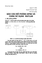
The high-level architecture of an IPTV environment
comprises four key blocks, each one with particular functions
and interdependencies [1]. The main elements of the IPTV
environment are depicted in Figure 1. The first block is the
content provider and involving only the information sources,
the security and operating problems are not implicated. For
example, the information sources may be a capture camera,
* Ing. I.S.Comsa is with Technical University of Cluj-Napoca, Romania,
Communications Department, email:
[email protected]
** Prof. R. Arsinte is with Technical University of Cluj-Napoca, Romania,
Communications Department, email:
[email protected]
Fig. 1. IPTV high-level architecture
multimedia encoding platform [2].
The packetizing and encapsulation of video content involves
inserting and organizing video data into individual packets.
There are a couple of different approaches to encapsulating
video content, namely, MPEG over IP and VC-1 over IP. The
IPTV communications model is a networking framework
composed of seven (and one optional) conceptual layers that
are stacked on top of each other (Figure 2) [2].
The communication process starts with the MPEG
elementary stream that is outputted from the encoder. The
types of information included in an elementary stream can
Traffic _ rate =
total _ bytes
[ Bps ]
transmission _ duration
(1)
B. Inter-packet delay
Inter-packet delay represents the delay between transmitted
and received packets. This parameter depends on number of
nodes (routers), network traffic, routing protocols. The
average value is defined in expression (2). It is important to
note that all the stations must to be synchronised.
Interpacket _ delay =
Delay1 + Delay 2 + ... + Delay N
[s]
N
(2)
C. Inter-packet jitter
Inter-packet jitter is a variation of the inter-packet delays
and it is a very important parameter for real time streaming.
The average jitter is defined with the formula number (3).
Fig. 2. The IPTV communication model [2]
include: frame type and rate, positioning of data blocks on
screen, aspect ratio [2].
In order for the audio, data, and video elementary streams to
be transmitted over the digital network, each elementary
stream is converted into an interleaved stream of time stamped
Packetized Elementary Stream (PES) packets. A PES stream
contains only one type of data from one source. A PES packet
may be a fixed (or variable) sized block, with up to 65536
bytes per packet[2].
The transport stream is formed by breaking up the PES
packets into fixed-sized TS packets of 188 bytes that are
referenced to independent time bases. Each TS packet contains
one of the three media formats, video, audio, or data.
For VC-1, the encapsulation mechanisms are similar to the
MPEG. The transport mechanism involves encapsulation of
VC-1 access units (AUs) inside a series of RTP packets. Each
AU contains a header and variable length video payload [2].
In real-time streaming, the video content is sent using the
RTP(Real-time Transmission Protocol) over UDP(User
Datagram Protocol). For VoD transmission the protocol used
is RTSP(Real-time Transmission Streaming Protocol) over
TCP(Transport Control Protocol).
II. QOS PARAMETERS FOR IPTV
Quality of Service represents the capacity of the network to
ensure better services for a selected type of traffic. The QoS
target is to assure a band allocation, to control the delay and
jitter and to reduce the number of packet loss [3].
QoS parameters are divided in two parts: for real-time
streaming and for VoD content. QoS parameters for real-time
streaming are: traffic rate, inter-packet delay, start delay, jitter,
number of lost packets, number corrupted packets, number of
reordered packets.
A. Traffic Rate
Traffic rate indicate the capacity of network to permit a type
of transmission. Define the number of packets during the
transmission. Dividing the number of bytes by the transmission
duration we obtain the traffic rate
Jitter =
Jitter1 + Jitter2 + ... + JitterN
N
[s]
(3)
D. Packet-loss parameter
The packet-loss parameter is defined in conjunction with the
path between source and destination where the packet can be
lost or eliminated by the router if the buffer is full [3]. If the
packet is corrupted, it is declared lost. The lost of packets is
depending on the current state of the network which cannot be
anticipated. The algorithm used for packet-loss is the
monitoring of the RTP sequence number and according to this
it can make a decision if the packet between two sequence
numbers is lost or not.
Some bits transmitted through the network can be corrupted.
This can affect the quality if the number of corrupted bits is
high. The parameter that can evaluate the number of corrupted
packets is PER(Packet Error Rate) calculate with the formula
(4).
PER =
Number _ corrupted _ packets
× 100%
Number _ received _ packets
(4)
The packet reordering appears when at the receiving side,
the packets can arrive out-of-order because of the different
paths chosen by routers. A packet is considered reordered if
the sequence number is smaller than the sequence number of
the previous packet received. We use the RTP sequence
number of the packets for every UDP port used during
transmission.
III. THE PROPOSED ARCHITECTURE
The implementation of an IPTV network requires the use of
different types of technologies. They may relate to the
operating systems that are used for the stations involved. The
proposed architecture (an enhanced version of the architecture
proposed in [4]) is using two operating systems: Windows and
Linux. In this case the IPTV network became heterogeneous.
These operating systems use the combination of another
types of technologies: Windows Media Services 9 (WMS) and
Video LAN(Local Area Network) Server(Client). Windows
Media Services are used only by the Windows stations. VLC
or VLS is running on both station types: Windows or Linux.
The main idea is based on forming an IPTV mini-network
which follows the architectural model with the translation and
transmission methods necessary to ensure an acceptable QoS
level. Figure 3 illustrates this concept: the capture camera, the
Windows Media Encoder and the Technisat DVB receiving
card form the content provider block, the Windows Media
Server, DVBViewer program and VLC Windows Server 1
represents the IPTV service providers, the VLC Windows
server 2 and the first router take place of the transport and
aggregation network and the VLC Linux server 3 with the
Reception
Antenna
DVBViewer
Station
VLC Windows
Server 1
TechniSat Card
IP: 10.150.4.33
IP: 10.150.4.33
IP:193.168.0.1/24 Mask: 255.255.224.0 Mask: 255.255.224.0
Multicast address:
D.G:10.150.0.1
D.G:10.150.0.1
224.0.0.1
VLC
Windows
Server 2
HTTP Server
Windows Media
Encoder
VLC
SLAX Router 1
Linux
Interface 1: 10.150.4.1/24 Server 3
Interface 2: 10.150.5.1/24
SLAX Router 2
Interface 1: 10.150.5.3/24
Interface 2: 10.150.6.1/24
VLC
Linux
Client
Windows Media
Server
IP address: 10.150.4.2
Subnet Mask: 255.255.255.0
Gateway: 10.150.4.1
IP address: 10.150.4.40
IP address: 10.150.4.10
Subnet Mask: 255.0.0.0 Subnet Mask: 255.255.224.0
Gateway: 10.150.4.115
Gateway: 10.150.0.1
IP address: 10.150.5.2
Subnet Mask: 255.255.255.0
Gateway: 10.150.5.3
IP address: 10.150.6.2
Subnet Mask: 255.255.255.0
Gateway: 10.150.6.1
Fig. 3. The proposed IPTV test architecture
second router can be seen as a access mini-network.
The scenario involves three types of streams. The first is
taken from a capture camera, it’s CBR coded by Windows
Media Encoder transmitted forward to the Windows Media
Server using HTTP protocol. The second stream is a VoD type
and is generated by the encoder. Another stream is taken from
the DVBViewer, a program that transforms the radiofrequency signals from the different types of satellites,
containing a large number of channels and encode it for
multicast transmission to a VLC Windows server 1.
The Windows Media Encoder with IP address
10.150.4.40/24 converts the video content into a digital form
and then encapsulated it to be sent to Windows Media Server.
VC-1 is the technique that is used.
Windows Media Server(IP address: 10.150.4.10/24) is
receiving the audio-video content using the HTTP and TCP
protocols. The connection between encoder and server is set
with the command http://10.150.4.40/Encoder:80. The video
content is distributed by the Media Server through Channel1.
This channel transmits in multicast type the media information
to the VLC Windows Server 2. However, the VLC server 2
can access the windows media content using MMS
protocol(mms://10.150.4.10/Channel1). This server is running
at the station with 10.150.4.2/24 IP address. His role is to
trans-code the WMS video content from VC-1 format into
H.264&AAC format, so that the output stream to be recognized
on Linux stations.
The second stream is generated on the encoder station and is
transmitted directly to VLC Windows Server 2 without any
trans-coding techniques.
The third stream is taken from Technisat network card with
193.168.0.1/24 IP address. DVBViewer is an interface
between this network card and user. The stream is transmitted
from the DVBViewer station on 224.0.0.1 IP multicast address
and 7792 transmission port. The interface address for DVB
program is 193.168.0.1/24.
The VLC Windows Server 1 is responsible for transforming
the RTP multicast transmission into RTP unicast transmission,
such as the resulting stream to be transmitted to the VLC
Windows server 2 in MPEG TS format. This server is running
on 10.150.4.33/24 IP address and the transmitting port is
1234.
All of these streams are sent to the VLC Windows Server 2.
The role of this server is to aggregate all the streams received
and represents the first element of the private network.
All traffic is sent to the VLC Linux Server 3 through the
first router. This is simulated using a station with SLAX Linux
distribution. This will have two interfaces with IP address,
identical with the default gateways of the VLC servers:
10.150.4.1/24, 10.150.5.1/24. First, it adding the interface and
network addresses.
ip addr add 10.150.4.1/24 brd + dev eth0
ip addr add 10.150.5.1/24 brd + dev eth0
ip route add 10.150.4.0/24 dev eth0
ip route add 10.150.5.0/24 dev eth0
The VLC Linux Server 3(10.150.5.2/24) takes the streams
from VLC Windows Server 2. The role of this server is to
forward the traffic to the VLC Linux Client through the second
router with SLAX distribution. The default gateways are:
10.150.5.3/24 and 10.150.6.1/24. For routing the packets, at
the both routers, the variable /proc/sys/net/ipv4/ip_forward is
set to the value 1.
echo 1 > /proc/sys/net/ipv4/ip_forward
VLC Linux Client is receiving all the traffic on
10.150.6.2/24 IP address.
On the VLC Linux Server and Client will monitor the QoS
parameters with an application named sniffer.c. This program
will measure the traffic rate, inter-packet delay, jitter and
packets loss only on the last stations.
For the remaining network will analyze the traffic rate, the
other parameters are negligible because of the gigabit local
area network.
Sniffer.c was compiled under Linux using gcc. First, it
initializes the parameters like filter port, interface, number of
received packets, missing frames, etc. The capture interfaces
are eth0 and eth1. Setting the interface, the program obtains
the network and mask addresses.
After the creation of the principal thread, the types of
information printed in three files are: the index of received
packet and the time stamp, the number of lost packets at every
time stamp and the accumulated values of lost packets at the
moment when the lost is detected.
The packet loss is detected using the RTP sequence number.
The difference between two RTP sequences is printed in the
packet loss file. If the difference is not 1, then the loss of
packets is detected and the values are printed at the moment of
time when the last RTP sequence is captured by the interface.
The measurement of the one way delay parameter implies
very good clock synchronization between the server and the
receiver, because the delay is obtained by comparing the time
stamps of the sent and received packet. Any synchronization
problem between the two elements leads to erroneous values.
The VLC Linux server 3 and client are synchronized using the
ntp.conf file. With it, the client takes the time in h/m/s/ms
format from the server. By making the difference between the
time stamps when the packets are sent by the server and the
time stamps when the packets are received on the client side,
we obtain the inter-packet delay and the jitter.
• Audio codec: Windows Media Audio 9;
• Total rate: 1273,03kbps
• Encoded packet size: 1400 bytes;
On the VLC Windows Server 2 the traffic rate for these
streams are indicated in Figure 4. The average traffic rate for
the stream generated by the capture camera (green line) is
0,7Mbps. For the second stream, generated locally by the
encoder, the average value is 0,9Mbps (blue line) and for the
stream generated by the DVBViewer the average traffic rate is
3,7Mbps (red line).
IV. EXPERIMENTAL RESULTS
Experimental results are obtained by the simultaneous
transmission of the streams described in the previous
paragraph. All the streams are started by the generating
stations and programs and are sent to the VLC Windows
Server 2. This server transmits the streams to the VLC Linux
Sever 3 on the following ports: the stream that is generated by
the capture camera is sent on the port 5000, the second one on
the port 5001 and the stream generated by DVBViewer is
transmitted on the port 5002. At the VLC Linux client the
streams are received on 1240, 1241 and 1242. So, the pairs of
ports where are evaluated the QoS parameters are: 5000-1240,
5001-1241 and 5002-1242 corresponding to the streams in the
order mentioned before.
On the first stream, the parameters for Media Encoders are:
• Audio-video encoding mode: CBR (Constant Bit
Rate)
• Buffer length: 1 second;
• Video smoothness: 70;
• Frame rate: 29,97 fr/s;
• Video size: same to the input video;
• Video rate:1200kbps;
• Video codec: Windows Media Video 9;
• Audio format: 64kbps, 48kHz, stereo CBR;
Fig 5. Traffic rate on 5000 and 1240 ports
First we evaluate the transmission rate between the VLC
Linux server 3 and client. For the first stream the number of
transmitted packets is 16000. Within one minute the number of
packets that are transmitted from 5000 to 1240 ports is 4000
(Figure 5). Traffic rate can be calculated with formula (5). A
packet contains 1372 bytes.
D=
For the second stream, the number of transmitted packets from
the port 5001 to the port 1241 in 5 minutes is 29000. Within
one minute the number of transmitted packets is 5000. The rate
is determined with the formula (6).
D=
Fig 4. Traffic rate on the VLC Windows Server 2
Number _ of _ packets 4000 × 1372 × 8
=
= 0, 7 Mbps (5)
Minute
60
Number _ of _ packets 5000 × 1370 × 8
=
= 0, 9 Mbps
Minute
60
Fig. 6. Traffic rate for the second stream
(6)
(figure 9). The negative value is caused by the difference
between the minimum and maximum value of the inter-packet
delay.
Fig. 7. Traffic rate for the DVBViewer stream
The number of transmitted packets for the third stream in one
minute is 20000. Furthermore, the computed rate is 3,7 Mbps
(equation 7).
D=
20000 × 1372 × 8
= 3, 7 Mbps
60
(7)
Fig. 10 Inter-packet delay for the second stream
For the local generated stream the maximum value for interpacket delay is 4,1904033s, the average is 0,2711245s and the
minimum delay is 0,1744169s. The average jitter is 0,000098s,
Figures 6 and 7 are presenting the same parameters (traffic
rate) for the second and third streams.
To determine the inter-packet delay and jitter we are
considering the first 10000 transmitted packets for all the
streams.
For the associate transmission of 5000 and 1240 ports, the
inter-packet average value is 2,83204s, the maximum value is
5,9112452s and minimum is 0,2219906s (figure 8).
The average value obtained for jitter is 0,00511228, the
minimum is -4,0012545s and the maximum 4,0012545s
Fig. 11 Jitter for the second stream
Fig. 8 Inter-packet delay for the first stream
Fig. 9 Jitter for the first stream
the minimum and maximum values are: -3,9998893s and
4,0008256s (figures 10 and 11). The minimum value of the
delay is smaller than the value obtained at the first stream. The
same it happens with the maximum value.
At the transmission of the stream generated by the
application DVBViewer an inter-packet delay average value of
0,2156974s is obtained, and the maximum and minimum
values are 0,2541312 and 0,1851437, respectively. At the jitter
the average, minimum and maximum values are: 2,75858E-5s,
-0,2343453s and 0,0179553s, respectively (figure 12 and 13).
This type of stream offers a better performance than the
second stream from inter-packet delay and jitter points of
Fig. 12 Inter-packet delay for the third stream
Fig. 17 The number of lost packets on port 1241
Fig 13 Jitter for the third stream
Fig.18 The number of lost packets on port 5002
Fig. 14 The number of lost packets on port 5000
Fig. 19 The number of lost packets on port 1242
Fig.15 The number of lost packets on port 1240
(Figure 15).
Within 8 minutes, on port 5001, the number of received
packets is 44 386 and 71 are declared lost. It represent 0,16%
percentage of a total received packets. On the sample of 20000
received packets, 10 packets are lost (Figure 16).
The number of received packets on port 1241 is 44361 and
63 are lost representing a 0,14% percent from the total number
of received packets. For a sample of 20000 received packets, 8
are lost (figure 17).
The port 5002 receives 106 039 packets and 57 are declared
lost (a percentage of 0,03%). Figure 18 illustrates the number
of lost packets on a sample of 20000 received packets. Figure
19 is presenting the same parameter for port 1242.
Fig. 16 The number of lost packets on port 5001
V. CONCLUSIONS AND FURTHER WORK
view.
To determine the number of lost packets, we consider the
number of received packets for each port of the respective
stream. In this test scenario, the duration of the transmission
for all streams is 8 minutes.
The received packets on port 5000 are 26436 corresponding
to a duration of 8 minutes. The total number of lost packets is
100, representing a percentage of 0,38%. For a sample of
20000 packets, the number of lost packets is 16 (figure 14).
On port 1240 at the VLC Linux client, the number of the
received packets is 24864 of which 74 are declared lost
(percentage of 0,3% from total received packets). On a sample
of 20000 received packets the number of lost packets is 18
For a final overview of the results, in Table 1 we are
marking the worst case (blue) and the best performance (red)
of all streams from QoS parameters point of view. White cells
of the table represent neutral values.
The first stream, generated by the camera stream capture,
offers the worst results for all QoS parameters. The traffic rate
is 0,7Mbps. For this stream, part of information is lost because
of H.264 transcoding process performed in VLC Windows
Server 2.
For the second stream generated locally on the encoder
station, is obtained the minimum of inter-packet delay
(0,1744169s).
The third stream generated by DVBViewer offers the best
values for maximum and average inter-packet delay,
maximum, minimum and average jitter and the percentages of
lost packets on ports 5002 and 1242 are the smallest. This can
be easily explained, since digital video broadcasting content is
already MPEG encoded and packetized.
TABLE I
STREAMING PERFORMANCE FROM QOS POINT OF VIEW
Streams/QoS Parameters
Stream 1
Stream 2
Stream 3
Rate
-
Maximum interpacket
delay
Average interpacket
delay
Minimum interpacket
delay
-
Maximum interpacket
jitter
-
Average interpacket
jitter
-
Minimum interpacket
jitter
Percentage of lost packets on
port 5000
-
-
Percentage of lost packets on
port 5001
-
-
Percentage of lost packets on
port 5002
Percentage of lost packets on
port 1240
Percentage of lost packets on
port 1241
Percentage of lost packets on
port 1242
-
-
-
-
-
-
-
-
Similar systems and comparable results are presented in [8],
and this is encouraging us to continue the development of the
evaluation system.
This study is showing clearly that the power of general
purpose computers is limited, when complex manipulations of
information, like transcoding, are needed. In this case
dedicated hardware (based on ASICs or FPGAs) must be
employed, to ensure a proper quality for IPTV services.
Future work will be dedicated to more test scenarios,
implemented in an even more real IPTV environment, with
multiple users and different streaming applications. It is
possible to add the evaluation not only of the streaming
parameters, but also for additional elements, specific to IPTV
applications. Such elements are suggested in work [9].
A real challenge will be to evaluate the IPTV QoS in
physical networks different from Ethernet, like WiFi
(suggested in [10]) or ADSL [11]. Reference [12] contains
several test scenarios and a large number of measurements.
REFERENCES
[1]
David Ramirez, IPTV Security Protecting High-Value Digital Contents,
Wiley-Interscience, 2008
[2] Gerard O’Driscoll, Next Generation IPTV Services and Technologies,
Wiley-Interscience, 2007
[3] Ancuta Sanda Buzila, Gabriel Lazar, Tudor Blaga, Virgil Dobrota,
"Evaluation of QoS Parameters For IPTV", Acta Technica NapocensisElectronics & Telecommunications, Volume 48, no.3, 2007, pp. 9-14
[4] Radu Arsinte, "An Experimental Architecture For Basic IPTV Concepts
Implementation and Testing", Acta Technica Napocensis- Electronics &
Telecommunications, Volume 49, no.4/2008, pp.15-18
[5] V. Dobrota, Digital Networks in Telecommunications: Volume III OSI
and TCP/IP, Second Edition, Mediamira Science Publishers, ClujNapoca, 2003
[6] “VLC - The Cross-Platform Media Player and Streaming Server”,
[Online] Available: www.videolan.org/vlc/
[7] Wireshark, [Online] Available: http://www.wireshark.org,
[8] P. Begovic, N. Behlilovic, N. Mastilovic, "Comparation of QoS
parameters of received IPTV signals, using different compression
algorithms for streaming Live or Stored AV Materials", Proc. of 15th
International Conference on Systems, Signals and Image Processing,
2008. IWSSIP 2008. , pp.469 - 474
[9] Jörg Nonnenmacher, "Video QOS Measurement with Castify CBN",
Report, Castify Networks, 2005, Available: http://www.castify.net/
white_papers/pdf/qos_measurement_whitepaper_cbn.pdf
[10] F.E. Retnasothie, M.K.Ozdemir, T. Yucek, H. Celebi, J. Zhang, R.
Muththaiah, "Wireless IPTV over WiMAX: Challenges and
Applications", Proc. IEEE Annual Wireless and Microwave Technology
Conference, 2006. WAMICON '06, Clearwater Beach, pp.1 - 5
[11] F. Palacios, "IPTV Testing Over DSL", Application Note, EXFO
Corporate, 2006, Available: http://documents.exfo.com/appnotes/
anote148-ang.pdf
[12] I. Comsa, "Elaborarea de metode şi proceduri pentru translaţia în IPTV",
MSc dissertation, Communications Dept., Technical University of ClujNapoca, Romania, 2010