EMC Problems of Power Electronic Converters
DRABEK Pavel
#
Department of electromechanics and power electronics, West Bohemia University in Pilsen
Univerzitni 26, Plzen, Czech Republic
[email protected]
Abstract - Power electronic converters produce not only
characteristic harmonics, but also both non-characteristic
harmonics and interharmonics. This paper presents the physical
background of both non-characteristic harmonics and
interharmonics. Generation causes are explored and discussed
in detail. Extensive series of simulation of different power
converter topologies are provided and compared with
experimental results and existing standards. This research offers
missing background for standards covering low-frequency
EMC.
etc. Hz at 50 Hz power grid).
f = h * f1 where h is an
Non-Characteristic Harmonic
integer > 0 except characteristic harmonics (f=50, 250, 350,
550, 650 etc. Hz at 50 Hz power grid).
f = 0 Hz (f = h* f1 where h = 0)
DC
f ≠ h * f1 where h is an integer > 0
Interharmonic
f > 0 Hz and f < f1
Sub-harmonic
Where f1 is the fundamental power system frequency (50
Hz).
I. INTRODUCTION
As the power electronic converters find wide application in
power systems, power quality is becoming a more important
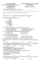
issue to consider. The operation of indirect frequency
converters with IGTB (see Fig.1) brings a lot of advantages
(new control methods, new steering algorithms etc.), but is
often accompanied by some unfavourable effects (e.g. [1][5]). The converter adversely influences the power grid due to
non-sinusoidal taken current, fed motor by transient motor
overvoltage and also converter control circuits. The power
quality is primarily influenced by the electric appliances
connected to the power grid. If a linear load is connected to
the power grid, the resulting current will be a sine wave (only
the fundamental frequency will appear). However, if the load
is non-linear, drawing short pulses of current within each
cycle distort the current shape (non-sinusoidal) and higher
frequency current components will occur - the resulting
current will be composed of the fundamental and higher
frequency components.
The problems concerning characteristic harmonic currents
of converters (arise due to converter function), their causes,
negative effects in the power distribution network and ways
to minimize them, are relatively well-known (e.g. [3]-[6]).
There has been less attention paid to non-characteristic (under
non-symmetry in the circuit) and interharmonic (under
dynamic changes in the circuit) current components in
practice and the literature (e.g. [4]-[5],[7]-[11]). These
frequency components are transferred to the power grid,
where they can cause distortion of supply voltage, disturbance
of connected equipment (ripple control devices, compensation
units), etc.
This paper looks mainly at the uncontrolled diode bridge
rectifiers with capacitive load and the three-phase fully
controlled bridge rectifier feeding an inductive load.
According to standards the low-frequency interference is
considered on a frequency range 2.5 kHz and the frequency
components can be defined as follows:
II. THREE PHASE UNCONTROLLED BRIDGE RECTIFIER
In the case of a frequency converter with voltage source
inverter (see Fig.1), we can divide the circuit into inverter part
and rectifier part supplying capacitor in the DC Bus.
Characteristic Harmonic f = (h*p ± 1) * f1 where h is an
integer > 0, p – number of pulses of output voltage (for 3f
bridge rectifier p=6, therefore f=50, 250, 350, 550, 650
978-1-4577-0811-4/11/$26.00 ©2011 IEEE
D istribution
Network
Frequency Converter
Induction
Motor
M
R e ctifie r
Voltage
Inve rte r
Fig. 1: Block diagram of the drive with frequency converter
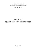
Three-phase bridge rectifier as an input part of the static
converter (see Fig.2) is modelled with the focus on the
calculation of all harmonic components present in the current
taken by the rectifier from a power distribution network. It
requires a mathematical model of the AC/DC converter.
Fig. 2: Three-phase bridge rectifier configuration
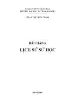
The typical waveform of a taken phase current under ideal
operating conditions (symmetrical power supply, indefinite
short circuit power etc.) is shown in Fig.3. The non-sinusoidal
waveform of a phase current creates higher frequency current
components. For the harmonic components calculation of
phase current it is necessary to simplify the phase current
wave as is shown in Fig.3.
Amplitude Im is constituted so that the area of both
currents will be identical for the same parameter d (where d is
a diode conduction time). From the figure it is obvious that
used simplification is rough in commensurate with the value
of parameter d. The error of used simplification decreases
734
with the decreasing of parameter d and for small value d
corresponds to reality.
Fig. 3: Real and simplified phase current wave
Using the well-known quotation for Fourier analysis we
can calculate coefficients ah and bh. Since the current
waveform from Fig.3 is symmetrical odd function,
coefficients ah are zero and we can solve coefficients bh only:
2π
bh =
∫ i (ωt ) sin(hωt )dωt
III. NON-CHARACTERISTIC HARMONICS
Under real conditions, unbalanced power source amplitude or phase non-symmetry, the considered problem
becomes more complicated and in the frequency spectrum we
can find also non-characteristic components. In contrast to
characteristic harmonics for calculation amplitudes of noncharacteristic harmonics we can not use equation (5) and we
have to apply numerical Fourier analysis (DFT or FFT) for
investigation of frequency spectrum of a taken current.
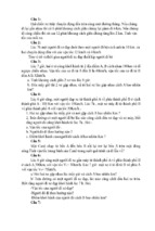
Voltage and current circumstances at single phase voltage
power source non-symmetry you can see in Fig.5. Power
source non-symmetry causes distortion of phase currents and
drift of basic harmonic wave of phase current against phase
voltage.
(1)
f
π
0
After editing we will get:
()
4I m ⎡ ⎛ hk ⎞
⎛ hk
⎞⎤
⎛ hπ ⎞
(2)
sin⎜ ⎟ − sin⎜ + hd ⎟⎥ ⋅ sin⎜ ⎟
hπ ⎢ ⎝ 2 ⎠
⎝ 2
⎠⎦
⎝ 2 ⎠
⎣
For symmetrical power network is valid d+k=600 and relation
(2) we can convert to:
bh = −
8I m
hd
hπ
hπ
⋅ sin
⋅ cos
⋅ sin
2
6
2
hπ
bh =
(3)
The Back expression of current i by Fourier progression is:
∞
i f (ωt ) = ∑
h =1
8I m
hd
hπ
hπ
sin .sin
. cos
.sin( hωt )
hπ
2
2
6
(4)
For higher current harmonics amplitudes are valid:
I
h
1
I1.
=
h
hd
2
d
sin
2
sin
Fig. 5: Voltage and current waveforms at single phase voltage source
non-symmetry
(5)
The frequency spectrum of phase current from Fig.5
contains non-characteristic harmonics of an odd multiple of
three only (Fig.6) and their amplitudes depend on the value
of voltage source non-symmetry (Fig.7).
where
I1 =
8 I fm
π
⋅ sin
d
π
d
⋅ cos = 2,205 .I fm . sin
2
6
2
(6)
When we use the relation (4), we find out that only
harmonics of a definite order (5., 7., 11., 13. etc.) will appear
on a frequency spectrum (Fig.4). These harmonic orders are
called characteristic harmonics and their amplitudes are
solved by an equation (5).
Fig. 6: Frequency spectrum of taken phase current at 3% power
source non-symmetry
Fig. 4: Frequency spectrum of ideal current wave
The value of non-characteristic harmonics increases with
voltage non-symmetry rising and it results in low decrease of
characteristic harmonics. A drop of dominant harmonics has
influence on coefficient THDi low decrease, but then
increasing of third harmonic causes a low rising of coefficient
THDi (Fig.8). In the following figures you can see a
comparison of simulation and experimental results. The
measurement of harmonic components was carried out
735
according to the scheme in Fig.1 and has been measured by a
frequency analyser.
Waves of quantities on Fig.7-8 are displayed for definite
circuit configuration (Lq, LSS, CSS, diode voltage drop etc.).
It is obvious that a change of these circuit parameters
influence phase currents and consequently values of
harmonics. Dependence of non-characteristic and
characteristic harmonics on circuit parameters LSS and CSS
is shown on Fig.9-10.
Fig. 7: Non-characteristic harmonics in dependence of voltage
power source non-symmetry
Fig. 10: Characteristic harmonics in dependence of parameters LSS
and CSS
Fig. 8: Characteristic harmonics and THDi in dependence of
voltage source non-symmetry
Fig. 9: Non-characteristic harmonics in dependence of parameters
LSS and CSS
IV. INTERHARMONICS
Excepting characteristic and non-characteristic harmonics
discussed in the previous paragraph, we can also find
interharmonic components in frequency spectra of consumed
current (see Figure 11). The interharmonics occur as a
consequence of dynamic changes of circuit parameters (power
supply voltage dips, load variation, control interventions
(machine start-up, speed reversal transient) - generally
feedback controller impact). The interharmonic current
magnitudes are relatively small in comparison with
characteristic and non-characteristic harmonic components,
but they may impact the proper function of neighbouring
appliances (e.g. interference of ripple control and tuned
filters).
At first, the impact of single phase voltage change on the
interharmonics is explored. In case of single phase voltage
change, we will change the amplitude of the second phase
only as is shown in Figure 12 and appropriate frequency
spectrum is in Figure 13. Size of voltage change ΔU has a
major influence on the interharmonics and it is determined in
percent of phase voltage amplitude within the calculation
window TW=160 ms (that means voltage decrease during
eight fundamental periods). Due to single phase voltage
change, current waveforms are heavily distorted that appears
at frequency spectrum of interharmonics. Also the DC bus
voltage is distorted; it has bigger ripple and lower pulsation
(from six pulses it floats to four pulses). For higher ΔU,
distortion of phase currents is so high that the classical double
pulse waveform of phase current changes to a single pulse
waveform (Figure 12 – second phase). This pulse change of
phase current has a good influence on interharmonic
components and they decrease with increasing ΔU. On the
other hand it has an unfavourable effect on harmonic
736
components, mainly on the third non-characteristic harmonic
(as can be seen on fig. 13), which essentially increases.
Figure 15. Dependence of interharmonics on voltage decrease at three
phase voltage change
Figure 11. Measured frequency spectrum of phase current
The graph in Figure 15 presents the increase of
interharmonic currents with higher ΔU (almost proportional
dependence).
V. THREE PHASE FULLY CONTROLLED BRIDGE RECTIFIER
Basic disposition of three phase fully controlled bridge
rectifier is shown in Figure 16.
Figure 12. Voltage and current waveforms under single phase voltage source
change (ΔU = 8.8 % ≅ 29 V)
Figure13. Interharmonics under ΔU = 8.8 % ≅ 29 V
Figure 16. Basic disposition of AC/DC converter
Waveform of consumed current is affected by unbalanced
power source, non-accurate firing of thyristors, different
transformer leakage inductance. Thanks to these effects the
non-characteristic harmonic components will appear. Unlike
well-known characteristic harmonics, these components
cannot be deduced by means of the “1 over n rule”.
The influence of unbalanced power source is shown in
Figure 17. Power source non-symmetry causes arising of the
non-characteristic harmonics, which order is the odd multiple
of three only. Figure 18 illustrates their dependence on power
source non-symmetry. All non-characteristics of even orders
equal zero.
The amplitude non-symmetry of power source causes also
change of the phase of line voltage; therefore, the cycle of
current conduction should be different from 2π/3.
Figure 14. Dependence of interharmonics on voltage decrease under single
phase voltage change
In case of three phase voltage change, we will change the
amplitudes of all three phases of the power source. Figure 15
illustrates the dependence of interharmonic currents on three
phase voltage change.
Figure 17. Voltage at the load and phase current influenced by non-symmetry
of power source Δu=5%.
737
Figure 18. Dependence of the harmonics and THD on the power source nonsymmetry
The influence of firing pulses non-symmetry is described
in Figure 19. It is the main source of non-characteristic
harmonics of even orders. All these components are directly
proportional to the value of firing pulses non-symmetry (see
Figure 20). The dependence is almost linear. It is obvious
from the frequency spectrum that the 2nd harmonic exceeds
12%. It is an even larger value a the magnitude of the 7th
harmonic, which is characteristic and is presented in the
consumed current under ideal conditions. This means that the
level of harmonics is highly dependent on the accuracy of
thyristor firing.
Figure 21. Voltage at the load, phase current and voltage influenced by
three phase voltage change
The voltage change ΔU has a major influence on
interharmonic components (Figure 22) and it is determined in
percent of phase voltage amplitude.
Figure 22. Dependence of the concrete interharmonic (f=1,125 Hz) on
voltage decrease at three phase voltage change
Figure 19. Voltage on the load and phase current influenced by firing
pulses non-symmetry
In the next step, we will describe the impact of firing
pulses variation. There are at least three possible firing pulses
changes – change of all firing pulses, change of one thyristor
group (anode group or cathode group) and change of one
firing pulse only. On simulation and experimental bases, we
find out that change of all firing pulses (Figure 23, 24) has the
biggest influence on the interharmonics.
For comparison with another type, the dependence of
interharmonics on the value of one firing pulse change only is
displayed in Figure 25.
Figure 20. Dependence of the harmonics and THD on the value the
firing pulses non-symmetry
VI. INTERHARMONICS
Similar to the interharmonics of the uncontrolled rectifier
(mentioned before), amplitudes of interharmonics are
dependent on dynamic changes of circuit quantities – voltage
changes of supply source, converter load changes, change of
thyristor firing pulses, etc.
At first, the impact of phase voltage change of power grid
is presented – let us consider the voltage change in all three
phases (Figure 21).
Figure 23. Voltage at the load, phase current and voltage influenced by
firing pulses change
738
In the real power systems the waveforms of consumed
currents are always affected by combinations of many
influences. It is not easy to distinguish, which effect causes an
increase in each individual non-characteristic harmonic and
interharmonic. Consequently each power source nonsymmetry and other influences were considered separately.
The paper presented the physical background of both noncharacteristic harmonics and interharmonics. Generation
causes were explored and discussed in detail. Major factors
affecting the consumed current (Unbalanced Power Source,
DC Bus CSS and LSS, dynamic changes) were described.
Extensive series of simulation of different power converter
topologies were provided and compared with experimental
results and existing standards. The measurement difficulties
were discussed (measurements were performed in compliance
with actual standards).
Figure 24. Dependence of interharmonics on the value of all firing
pulses change
ACKNOWLEDGMENT
This research work has been made within research project
of Czech Science Foundation No. GACR 102/09/1164.
REFERENCES
[1]
Peroutka, Z., Drábek, P.: Electromagnetic Compatibility Issues of
Variable Speed Drives. In: IEEE SYMPOSIUM on Electromagnetic
Compatibility 2002. Minneapolis, Minnesota, USA 2002, pp. 308313.
[2]
Peroutka, Z. - Kůs, V.: Investigation of Phenomena in the System
Voltage Inverter - Cable - Induction Motor. In: European Power
Electronics and Applications (EPE) 2001. Graz, Austria. 2001.
[3]
Kloss, A.: Stromrichter-Netzrückwirkungen in Theorie und Praxis. AT
Verlag Aarau, Stuttgart 1981.
[4]
Ruppert, M.: Analysis of Non-characteristic Harmonic Currents of
Semiconductor Converters. [PhD thesis] West Bohemia University,
2002.
Figure 25. Dependence of interharmonics on the value of one firing
pulse change
[5]
Bauta, M., Grötzbach, M., “Noncharacteristic Line Harmonics of
AC/DC Converters with High DC Current Ripple,” In: 8th IEEEICHQP, Athens, Proc. Vol. II, pp. 755-760, 1998.
The special case is all firing pulses change. For example
the case of an AC/DC converter under transient conditions –
dc machine breaking. It presents the impact of control
intervention on the harmonic contents. During converter stop,
the phase current is heavily distorted. This effect will appear
in appropriated frequency spectrum. From the interharmonic
components point of view this is the worst case of firing
pulses change.
[6]
Arrillaga, J.: Power System Harmonic Analysis. John Wiley & Sons,
New York, 1997.
[7]
Drábek, P., “Analysis of interharmonic currents of power electronic
converters.” [PhD thesis]. University of West Bohemia, Plzeň, Czech
Republic, 2004. (in Czech).
[8]
KŮS, V.; DRÁBEK, P. Low Frequency Interference of Softstarters on
Power Distribution Network. In MiS 08. Warszawa : Wydawnictvo
Ksiazkowe Instytutu Elektrotechnyky, 2008. s. 1-6. ISBN 987-83922095-2-2.
VII. CONCLUSION
This paper described the behaviour of the three phase
uncontrolled bridge rectifier and fully controlled three-phase
bridge rectifier from the Electromagnetic Compatibility
(EMC) point of view with respect to low-frequency
interference. The first issue of this paper is non-characteristic
harmonics. These frequency components arise due to an
unbalanced condition in the power grid (such as unbalanced
voltage) and converter non-symmetry (e.g. non-symmetrical
firing angles). The second important part of this contribution
focused on the interhamonics. The interharmonics occur as a
consequence of dynamic changes of circuit parameters (power
supply voltage dips, load variation, control interventions
(machine start-up, speed reversal transient) - generally
feedback controller impact).
[9]
DRÁBEK, P.; KŮS, V.; FOŘT, J. Negative Influence of Controlled
Rectifiers on Power Distribution Network. In Power Electronics
Intelligent Motion Power Quality. Stuttgart : Mesago, 2007. s. 1-4.
[10] KŮS, V.; DRÁBEK, P.; FOŘT, J. Harmonic and Interharmonic
Currents Generated by Softstarters . In Power Electronics Intelligent
Motion Power Quality. Stuttgart : Mesago PCIM, 2007. s. 1-4.
[11] DRÁBEK, P. EMC issues of controlled rectifiers. In EPE 2007.
Brussels : EPE Association, 2007. s. 1-7. ISBN 978-90-75815-10-8.
739