d from ascelibrary.org by RMIT UNIVERSITY LIBRARY on 01/03/19. Copyright ASCE. For personal use only; all right
Electrical
Transmission and
Substation Structures
2018 Dedicated to Strengthening
our Critical Infrastructure
Proceedings of the Electrical
Transmission and Substation
Structures Conference 2018
Atlanta, Georgia November 4–8, 2018
Edited by
Michael Miller, P.E.
Downloaded from ascelibrary.org by RMIT UNIVERSITY LIBRARY on 01/03/19. Copyright ASCE. For personal use only; all rights reserved.
ELECTRICAL TRANSMISSION AND
SUBSTATION STRUCTURES 2018
Dedicated to Strengthening our Critical
Infrastructure
PROCEEDINGS OF THE ELECTRICAL TRANSMISSION AND
SUBSTATION STRUCTURES CONFERENCE 2018
November 4–8, 2018
Atlanta, Georgia
SPONSORED BY
Structural Engineering Institute of the
American Society of Civil Engineers
EDITED BY
Michael Miller, P.E.
Published by the American Society of Civil Engineers
Downloaded from ascelibrary.org by RMIT UNIVERSITY LIBRARY on 01/03/19. Copyright ASCE. For personal use only; all rights reserved.
Published by American Society of Civil Engineers
1801 Alexander Bell Drive
Reston, Virginia, 20191-4382
www.asce.org/publications | ascelibrary.org
Any statements expressed in these materials are those of the individual authors and do not
necessarily represent the views of ASCE, which takes no responsibility for any statement
made herein. No reference made in this publication to any specific method, product, process,
or service constitutes or implies an endorsement, recommendation, or warranty thereof by
ASCE. The materials are for general information only and do not represent a standard of
ASCE, nor are they intended as a reference in purchase specifications, contracts, regulations,
statutes, or any other legal document. ASCE makes no representation or warranty of any
kind, whether express or implied, concerning the accuracy, completeness, suitability, or
utility of any information, apparatus, product, or process discussed in this publication, and
assumes no liability therefor. The information contained in these materials should not be used
without first securing competent advice with respect to its suitability for any general or
specific application. Anyone utilizing such information assumes all liability arising from such
use, including but not limited to infringement of any patent or patents.
ASCE and American Society of Civil Engineers—Registered in U.S. Patent and Trademark
Office.
Photocopies and permissions. Permission to photocopy or reproduce material from ASCE
publications can be requested by sending an e-mail to
[email protected] or by locating a
title in ASCE's Civil Engineering Database (http://cedb.asce.org) or ASCE Library
(http://ascelibrary.org) and using the “Permissions” link.
Errata: Errata, if any, can be found at https://doi.org/10.1061/9780784481837
Copyright © 2018 by the American Society of Civil Engineers.
All Rights Reserved.
ISBN 978-0-7844-8183-7 (PDF)
Manufactured in the United States of America.
Electrical Transmission and Substation Structures 2018
iii
Preface
Downloaded from ascelibrary.org by RMIT UNIVERSITY LIBRARY on 01/03/19. Copyright ASCE. For personal use only; all rights reserved.
The planning and preparation of the Electrical Transmission and Substation Structures Conference
2018 required an extraordinary amount of time, effort, and dedication by the members of the
conference steering committee and the ASCE/SEI staff. The success of the conference is a direct
reflection of the level of effort by this group of volunteers.
The steering committee would also like to acknowledge the critical support of the sponsors and
exhibitors who made this conference a success through their exhibition displays and substantial
financial support.
This conference takes place every three years and provides sessions on Structural Analysis, Special
Design Considerations, Foundations, Structural Failure Analysis and Investigation, Substation
Design Issues, Seismic, Construction Challenges, Structure Upgrading, and much more.
On behalf of our dedicated volunteers and SEI staff, we would like to thank you for spending your
valuable time attending the Electrical Transmission and Substation Structures Conference. It is
our hope that you and your colleagues will benefit greatly from the information provided and make
professional connections that last for years
Acknowledgments
Conference Steering Committee
Michael Miller, P.E., M.ASCE
Conference Steering Committee Chair
SAE Towers
Anthony Di Gioia, Jr., Ph.D., P.E.,
.M.ASCE
DiGioia Gray and Associates, LLC
Frank Agnew, P.E., M.ASCE
Alabama Power Company
Leon Kempner, Jr., Ph.D., P.E., F.SEI,
M.ASCE
Bonneville Power Administration
Joel Bryant, P.E., M.ASCE
TAPP, Inc.
Gary E. Bowles, P.E., F.SEI, M.ASCE
ECI Engineers
Ronald Carrington, P.E., M.ASCE
POWER Engineers
Timothy Cashman, P.E., M.ASCE
Cashman Engineering, LLC
Dana Crissey, P.E., M.ASCE
Oncor Electric Delivery Company
© ASCE
Otto Lynch, F.SEI, M.ASCE
Power Line Systems, Inc.
Mary Jane McMillen, P.E., F.SEI, M.ASCE
AEP
Robert E. Nickerson, P.E., F.SEI, M.ASCE
Consulting Engineer
Wesley J. Oliphant, P.E., F. SEI, F.ASCE
EXO Group LLC
Archie Pugh, P.E., PMP. M.ASCE
American Electric Power
Downloaded from ascelibrary.org by RMIT UNIVERSITY LIBRARY on 01/03/19. Copyright ASCE. For personal use only; all rights reserved.
Electrical Transmission and Substation Structures 2018
iv
Ronald Randle, P.E., F.SEI, M.ASCE
EDM International
Marlon Vogt, P.E., M.ASCE
Ulteig Engineers
David Todd, P.E., M.ASCE
LG&E-KU Services Company
C. Jerry Wong, Ph.D., P.E., F.SEI, M.ASCE
DHW Engineering LLC
Sponsors
Premier
Powerline Systems
Silver
Beta Engineering
Black & Veatch Corporation
PLH Group, Inc.
Mitas Energy
Platinum
Valmont Utility
Sabre-FWT
TransAmerican Power Products
Electrical Consultants, Inc.
Trinity Meyer Utility Structures
Bronze
Fabrimet, INC.
Falcon Steel, Inc.
IEEE/NESC
NV5
Osmose Utilities Services
EXO
Leidos Engineering
Gold
SAE Towers Ltd.
DIS-TRAN Steel, LLC
TRC Engineers
SA-RA Group
POWER Engineers
Exhibitors (5/16/18)
3M Electrical Markets
All-Pro Fasteners, Inc.
Almita Piling
AMPIRICAL
Ampjack Industries, Ltd.
ASC
ASEC Inc.
Bell Lumber & Pole Company
Beta Engineering
Bold Transmission LLC
Boundry Layer Wind Tunnel Laboratory
Brooks Manufacturing Co.
Burns & McDonnell
Cantsink Manufacturing
CEATI International
Chemline
© ASCE
Commonwealth Associate, Inc.
Creative Pultrusions, Inc.
Custom Engineering Solutions, Inc.
DiGioia Gray, Inc.
DIS-TRAN Steel
EDM International, Inc.
Electrical Consultants Inc.
External Sun Steel Mast (Shanghai) Co.,
LTD.
EXO Group LLC
Fabreeka
Fabrimet
Falcon Steel America
FDH Velocitel
Frank X. Spenser & Associates, Inc.
(FSXA)
Electrical Transmission and Substation Structures 2018
Downloaded from ascelibrary.org by RMIT UNIVERSITY LIBRARY on 01/03/19. Copyright ASCE. For personal use only; all rights reserved.
GAI Consultants, Inc.
Gonzaga University
Hanson Professional Services, Inc.
HDR
Helical Pier Systems, Inc.
Highland Composites
Hubbell Power Systems
Hughes Brothers
IEEE/NESC
Kalpataru Power Transmission
Karamtara Engineering Private Limited
Keller: Cyntech, Hayward Baker,
McKinney Drilling, Seaboard Foundations
Kleinfelder
Klute Inc. Steel Fabrication
Laminated Wood Systems, Inc.
Locweld Inc.
Magnum Piering
McWane Poles
Mesa Associates, Inc.
Metalogalva North America Inc.
Mitas Energy and Metal Construction Inc.
Network Mapping Group
Oldcastle Enclosure Solutions
Osmose Utilities Services, Inc.
Paul J. Ford and Company
PFISTERER LAPP North America
Pile Dynamic, Inc./GRL Engineers, Inc.
PLH Group Inc.
Power Consulting Associates
Powerline Systems
Preformed Line Products
© ASCE
v
PUPI (Geotek)
Quanta Subsurface
Rohn Products
RS Poles
Sabre-FWT
SAE Towers
Sanpec
SA-RA Group
Sediver USA
Shaner Industries
Stella Jones
Summit Utility Structures
Superior Concrete Products
Surveying & Mapping, LLC
TAPP, Inc
Terra Remote Sensing (USA) Inc.
The Stresscrete Group
Threaded Fasteners, Inc.
Tower Drafting Services, Inc.
TransDesign International, LLC
TRC
Trinity Meyer Utility Structures
Ulteig
Utility Pole Solutions, Inc
V&S Schuler Utilities
Valmont Utility
W.E Gundy & Associates Inc.
Westwood Professional Services
Williams Form Engineering
Worley Parsons
Zhejiang Shengda Steel Tower Co., LTD.
Electrical Transmission and Substation Structures 2018
Contents
Downloaded from ascelibrary.org by RMIT UNIVERSITY LIBRARY on 01/03/19. Copyright ASCE. For personal use only; all rights reserved.
Construction Challenges
Structural Design and Construction Challenges on the South and West
of Edmonton Area Development Project ................................................................................. 1
Jondy Britton, Meagan Moeller, Wellan Cowan, Jacob Merriman,
and Chih-Hung Chen
Keeping the Project on Schedule—A Case Study about Emergency
Weld Repairs Required on a Newly Installed Vibratory Caisson ......................................... 11
Zachary J. Oliphant, Justin W. Curtis, Benjamin S. Jessup,
and Christopher W. Schnetzler
Mechanically Spliced Full Length Anchor Bolts—Bringing It All Together ........................ 23
Kolleen L. Backlund, Adam G. Bowland, Aaron P. Darby, Keith S. Yamatani,
and Nancy Z. Fulk
Construction Challenges in Paradise Hawaiian Electric Company—138 kV
System Rebuild ........................................................................................................................ 36
Mitchell Cowen and Garett Muranaka
Foundations
Guide for Transmission Line Foundations with Least Impact to Environment ................... 47
Peter M. Kandaris, Ashley E. Evans, and Asim Haldar
Practical Collaborative Approach to Alternative T-Line Foundations ................................ 62
Bridget Honsey, Jacob Hexum, Cole Vosters, Michael Bradley,
and Cliff Van Den Elzen
The Value of Structure-Specific Borings: Statistical Analysis of Electrical
Transmission Line Structure Foundation Costs Based on Structure-Specific
Borings versus No Borings or Variable Boring Spacing ........................................................ 70
Robert Chantome, James Knutelski, Darren Ratliff, Kevin Schilling,
and Daniel Whalen
Groundwork for Developing Comprehensive Transmission Line Foundation
Design Guidelines .................................................................................................................... 84
Peter M. Kandaris, Steve Davidow, and Ashley E. Evans
Posters
Composite Transmission Towers: Analysis, Behavior, Slip Investigation,
and Interaction Diagrams ....................................................................................................... 94
Mustafa Mahamid, Kamel Bilal, and Cenk Tort
© ASCE
vi
Electrical Transmission and Substation Structures 2018
Failure Analysis on Transmission Tower Struck by Tropical Storms ................................ 108
Jian Zhang and Qiang Xie
Downloaded from ascelibrary.org by RMIT UNIVERSITY LIBRARY on 01/03/19. Copyright ASCE. For personal use only; all rights reserved.
Effective Length Factor of Leg Member in Latticed Steel Tower ....................................... 122
M. L. Lu, M. Hao, and D. Chakrabarti
Seismic Effects on Transmission Lines and Their Major Components .............................. 132
Leon Kempner Jr., Scott Schlechter, and Asim Haldar
Program Considerations for Analysis of Drilled Shaft Foundations .................................. 146
Sanchit Chitre, Joel Coker, and Brian Sedgwick
Flood Design of Substation Structures ................................................................................. 157
Jared Augustine, Emily Larson, and Emily Bonini
Consideration of Sustained Loads and Creep Effects in Specifying and
Designing Fiber Reinforced Polymer (FRP) Utility Poles ................................................... 167
Diego S. Arabbo, Matthew C. Richie, and Scott J. DiFiore
A Full-Scale Crash Test for a Transmission Wood Pole...................................................... 176
Haijian Shi
Seismic Design of Substation Steel Structures: What Code Should I Follow? ................... 185
Hannah M. Hillegas and Prapon Somboonyanon
Analysis, Prediction, and Mitigation of Vortex Induced Vibrations in
Substation Structures ............................................................................................................ 191
Hossein Qarib and Diaaeldin Mohamed
Managing Aging Substation Structures ............................................................................... 199
Harinee Trivedi and Stefanie Gille
Seismic
Evolution of Electrical Grid Seismic Resiliency ................................................................... 209
John Dai, John Eidinger, Florizel Bautista, and Roderick Dela Cruz
Seismic Design of Substations—IEEE Standard 693 Gets a Major Update ....................... 219
Eric Fujisaki, Leon Kempner Jr., Brian Knight, and Craig Riker
Seismic Resiliency: What Utilities Should Know to Keep the Lights On............................ 233
Robert S. Cochran
Special Design Considerations
Aesthetics and Infrastructure: Accomplishing Both with Better Overall
Results for Power Delivery Projects ..................................................................................... 244
Kenneth Sharpless and Lynda Kiejko
© ASCE
vii
Electrical Transmission and Substation Structures 2018
Downloaded from ascelibrary.org by RMIT UNIVERSITY LIBRARY on 01/03/19. Copyright ASCE. For personal use only; all rights reserved.
Case Study for Behaviour of Transmission Line Structures under Full-Scale
Flow Field of Stockton, Kansas, 2005 Tornado .................................................................... 257
Ashraf A. El Damatty, Nima Ezami, and Ahmed Hamada
Evaluation and Implementation of Alternate Pole Materials to Meet
Regulatory Aesthetic Requirements ..................................................................................... 269
Clinton Y. Char and Alaira Bilek
Question: What Is an Acceptable Target Reliability for High-Voltage
Transmission Lines? ............................................................................................................. 281
Leon Kempner Jr.
Securing Steel Davit Arms: When and How? ...................................................................... 290
Meihuan Fulk, Blake Tucker, and David Parrish
Modeling and Quantifying the Aerodynamic Characteristics of Transmission
Line Structures to Avoid and Mitigate Aeolian-Induced Vibrations .................................. 302
Erik Ruggeri
Embrittlement in T.L. Lattice Steel Structures Specifying Energy Absorption
Criteria .................................................................................................................................. 312
Katherine Bridwell, Bhargava Vantari, Jonathan Kell, and Cesar Aguilar
Structural Analysis
Lattice Tower Deflection and Modeling of the Structure and Spans in Practice ............... 325
Saumya Nag, Steve Beilstein, Loren Jessen, Jonathan Frantz, Matthew Nicholson,
Khaled Kator, and Kevin Heller
Recent Duke Energy Studies to Develop Transmission Pole Standard ............................... 337
Prasad Yenumula, Jimmy Robinson Jr., and Neal Murray
Lattice Transmission Structures: Challenging Modeling Scenarios That
Require Non-Traditional Analysis Methods ........................................................................ 349
Kevin M. Wortmann and Ryan Z. Hann
Wood v. Steel: Dawn of Justice............................................................................................. 362
Otto J. Lynch
Heel or Toe? The Transmission Engineer’s Guide to Single Angles in Flexure ................. 372
Aaron Darby, Mary Jane McMillen, Nancy Fulk, and Robert Nickerson
Crossing the Delaware with PECO and a 300 ft Tall H-Frame Structure .......................... 385
Guy Faries and Kalpesh Patel
Updated Fall Protection Efforts for Transmission Structures ............................................ 393
David E. O’Claire and Mark D. Nelson
© ASCE
viii
Electrical Transmission and Substation Structures 2018
Structural Failure Analysis and Investigation
Downloaded from ascelibrary.org by RMIT UNIVERSITY LIBRARY on 01/03/19. Copyright ASCE. For personal use only; all rights reserved.
Evaluation of Typical Arm-to-Pole Connections in Slender Steel Pole
Transmission Structures for Wind Induced Vibration and Fatigue ................................... 407
Lawrence G. Griffis and Karl H. Frank
Fatigue Testing and Finite Element Modeling of Arm-to-Pole Connections
in Steel Transmission Pole Structures .................................................................................. 419
Francisco J. Bonachera Martin, Jason B. Lloyd, Robert J. Connor,
and Amit Varma
Welding Challenges in Typical Connections Used in Steel Pole Transmission
Structures .............................................................................................................................. 435
Jim Merrill and Wesley J. Oliphant
Challenges in Design and Mitigation of Wind-Induced Vibration for Slender
Steel Pole Transmission Structures ...................................................................................... 445
Daryl Boggs
Structure Upgrading
Great River Energy Transmission Line Tower Repairs ...................................................... 458
Kerby M. Nester and James M. McGuire
Teaching an Old Line New Tricks ........................................................................................ 472
Jimmy Buker and Deborah Knudtzon
Steel Transmission Pole Structural Capacity Uprating for High Voltage
Transmission Line and Substation Upgrade Projects ......................................................... 484
Chad Hines, Matthew Lohry, and Christopher Facklam
Substation Design Issues
Prefabricated Foundations—Construction Efficiencies and Economic Impacts ................ 496
Daniel S. Cuffman, Aaron P. Darby, and Olivialin A. Miller
Design and Construction of Riser Structures in Alberta ..................................................... 506
Kumar Kishor and Andrew Rees
Going against the Current: Short Circuit Force Background ............................................ 519
Alex J. Kladiva
© ASCE
ix
Electrical Transmission and Substation Structures 2018
Structural Design and Construction Challenges on the South and West of Edmonton Area
Development Project
Jondy Britton, P.E., M.ASCE1; Meagan Moeller, P.E., M.ASCE2; Wellan Cowan3; Jacob
Merriman, P.E., P.Eng., M.ASCE4; and Chih-Hung Chen, P.E., P.Eng.5
Downloaded from ascelibrary.org by RMIT UNIVERSITY LIBRARY on 01/03/19. Copyright ASCE. For personal use only; all rights reserved.
1
Burns & McDonnell, 9400 Ward Pkwy., Kansas City, MO 64114. E-mail:
[email protected]
2
Burns & McDonnell, 9400 Ward Pkwy., Kansas City, MO 64114. E-mail:
[email protected]
3
Burns & McDonnell, 9400 Ward Pkwy., Kansas City, MO 64114. E-mail:
[email protected]
4
Burns & McDonnell, 9400 Ward Pkwy., Kansas City, MO 64114. E-mail:
[email protected]
5
Burns & McDonnell, 9400 Ward Pkwy., Kansas City, MO 64114. E-mail:
[email protected]
ABSTRACT
In 2013, AltaLink initiated work on the South and West of Edmonton Area development
project comprised of multiple 138-kV and 240-kV circuit modifications. Scopes included
greenfield construction, rebuilding existing lines, and tapping existing lines to new substations.
The complicated project scopes were challenging to construct due to outage constraints,
environmental restrictions, and the need for multiple foundation solutions. Proper outage
planning with the AltaLink Control Center was imperative and directly impacted the construction
sequencing of the project. Environmental concerns affected the project in multiple ways: work
restrictions during bird nesting and migration seasons, requirements for rig matting in
environmentally sensitive and wet areas, and the use of vehicle wash stations. A variety of
structure types were implemented on the project including double-circuit latticed steel towers,
single-, double-, and triple-circuit tubular steel poles, and wood poles. Foundation types,
including drilled shafts, helical foundations, and direct embed foundations, were selected based
on structure type and location. Construction commenced in early 2017, and the project was
placed in service in December 2017.
PROJECT DEVELOPMENT PROCESS
Continued residential, commercial, and industrial growth south and southwest of Edmonton,
Alberta, has resulted in increased electric load in the area. The Alberta Electric System Operator
(AESO) forecasted that the winter peak load in the Edmonton planning region was expected to
grow from approximately 2,100 MW in 2011 to approximately 2,800 MW by 2022. The AESO
also forecasted that generation in the region would grow from approximately 4,600 MW in 2010
up to 5,400 MW by 2020 (AESO 2012).
The AESO concluded that transmission system reinforcement was needed to alleviate system
constraints created by load growth and generation expansion, and to comply with reliability
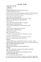
criteria. Following identification of the areas requiring transmission development, shown in
Figure 1, the AESO filed a Needs Identification Document (NID) with the Alberta Utility
Commission (AUC) for system reinforcement designated as the South and West of Edmonton
Area Transmission Development (SWEATD). The NID contained several alternatives, but the
© ASCE
1
Electrical Transmission and Substation Structures 2018
Downloaded from ascelibrary.org by RMIT UNIVERSITY LIBRARY on 01/03/19. Copyright ASCE. For personal use only; all rights reserved.
preferred option included four smaller sub-developments with scopes including the construction
of new substations, the modification of existing substations, and the construction of 240-kV and
138-kV transmission lines. The sub-developments were designated as Harry Smith, Cooking
Lake, Saunders Lake, and Leduc. The locations of the sub-developments relative to the area
requiring reinforcement are also identified in Figure 1.
Figure 1. Greater Edmonton Transmission Development Area (AESO Newsletter)
Once the SWEATD project was identified, the project process shifted toward public
notification and participation. The AUC notified the public of the AESO’s NID filing through
the commission’s website and local newspapers. After a public hearing process, the NID was
approved and the project progressed to the development of a Facility Application (FA) by the
selected Transmission Facility Operator, AltaLink. Throughout the FA process, AltaLink’s
project team narrowed the scope of each sub-development and incorporated feedback from the
public consultation process.
AltaLink compared the options for each sub-development by completing transmission line
optimization studies and conducting an involved public consultation process. Selection of the
preferred option required consideration of the environmental, aesthetic, and cultural impact of
the project, both during construction and post-energization. After public hearings and a review of
the FA, the AUC issued the permit and license to AltaLink to construct the transmission
facilities. The facilities were energized as planned at the end of 2017, meeting AESO
transmission system reinforcement requirements with an engineered solution that minimized
impacts to the environment and community.
A PORTFOLIO OF PROJECTS
Early in the planning stages of the project, a single-line diagram of the overall system was
developed to allow the project team to better visualize the scope of work, sequence of work, and
schedule dependencies between the sub-developments, and to start high-level outage planning.
© ASCE
2
Downloaded from ascelibrary.org by RMIT UNIVERSITY LIBRARY on 01/03/19. Copyright ASCE. For personal use only; all rights reserved.
Electrical Transmission and Substation Structures 2018
3
The Leduc and Harry Smith sub-developments were grouped in a sequence diagram to support
outage planning. The Saunders Lake and Cooking Lake sub-developments also were grouped in
a sequence diagram, as their outages and construction requirements were closely interrelated.
Using these sequence diagrams, the project team worked with the AltaLink Control Center to
develop a high-level outage schedule with milestone completion dates in support of the ultimate
in-service dates for all sub-developments. See Table 1 for a summary of the scope required for
each sub-development.
Table 1 - SWEATD Development Scope
Development 1
Development 2
Development 3
Harry Smith
Saunders Lake
Cooking Lake
240/138-kV Sub. 240/138-kV Sub.
Single-circuit
New
240-kV trans. line
Construction
Triple-circuit
138-kV trans. line
(2) 138-kV
Substations
Development 4
Leduc
Double-circuit
Double-circuit
240-kV trans. line
138-kV trans. line
Double-circuit
138-kV trans. line
(2) Substations
Double-circuit
240-kV trans. line
Leduc Sub.
Facility
Single-circuit
Double-circuit
Single-circuit 138Modifications 138-kV trans. line 138-kV trans. line kV trans. line
Single-circuit
Single-circuit
Single-circuit 138240-kV trans. line 138-kV trans. line kV trans. line
ROUTE AND SCHEDULE CONSTRAINTS
In addition to determining the optimal structure types for the project described in later
sections, there were many non-engineering considerations incorporated in design and project
execution for SWEATD, including environmental, visual, cultural, and land use impacts.
Throughout the transmission line route selection process, the routing team considered longer
span lengths to span wetlands, or the addition of angle structures to divert the alignment around
environmentally sensitive areas. The location of structures in proximity to roads determined the
types of foundations that could be used. Most structures near roads were located on road
allowance, a pre-arranged joint use right-of-way agreement between the Alberta Ministry of
Transportation and utilities in the province. Structure foundations located in the road allowance
were required to be less than two meters in diameter.
The construction team also had a number of work and schedule constraints to consider in its
execution planning. Construction required the use of rig matting. What started as a way for the
construction team to minimize impacts to wetlands ended up as a necessity to execute work. An
early spring thaw made it difficult for construction equipment to maneuver across the project site
without rig mats. The construction execution plan would also need to consider protocol if certain
bird species were encountered during their breeding seasons. During migratory nesting season
(March-July), bird and nest sweeps were required each day before construction could commence.
If a nest was encountered, the project team could be restricted to setbacks of up to 100 meters,
depending on the species, or could be required to stop work. Another constraint was clubroot
© ASCE
Downloaded from ascelibrary.org by RMIT UNIVERSITY LIBRARY on 01/03/19. Copyright ASCE. For personal use only; all rights reserved.
Electrical Transmission and Substation Structures 2018
infestation spread by infested farm machinery in canola fields near Edmonton. To minimize
clubroot spread due to project construction equipment, cleaning stations were required where
equipment crews entered or exited farm fields.
In addition to these development-wide requirements, certain sub-developments had
additional unique requirements to consider.
Cooking Lake Sub-Development: Part of the transmission line associated with the Cooking
Lake sub-development was proposed to be on the road allowance shared with the Alberta
Ministry of Transportation when parallel with Highway 14 and Range Road 220. While locating
the line within the road allowance minimized land impact since the land is designated for
transportation and utility use, there is a chance that the property could be reclaimed if the road
would need to be widened in the future. Additionally, the structures within the road allowance
along Highway 14 at the Highway 21 crossing were required to be taller than typical to
accommodate the Alberta Transport High Load Corridor clearance requirements. Additional
complications arose when transmission line alignment passed through a historical cemetery.
AltaLink conducted surveys adjacent to the alignment to determine if human remains would
require relocation prior to foundation installation.
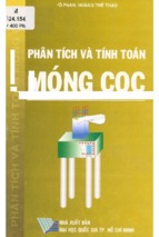
Figure 2. Tubular Galvanized Steel 240-kV H-Frame
(Courtesy of Burns & McDonnell)
Harry Smith Sub-Development: The Harry Smith sub-development presented unique
challenges due its proximity to a local private airport. The airport requested that the 240-kV
transmission line either be diverted from near its property or installed underground. Airport
officials believed an overhead transmission line could interfere with airport operations and would
be a safety hazard. However, moving the transmission line underground would significantly
increase project cost. AltaLink agreed to use H-frame structures with a maximum height of 25
meters above ground, shown in Figure 2, to remain below the airport’s Obstacle Limitation
Surface.
STRUCTURE AND FOUNDATION DESIGN
Overall, the SWEATD project involved designing and constructing eighty circuit-kilometers
of new 138-kV and 8 circuit-kilometers of new 240-kV transmission lines. The project team had
© ASCE
4
Electrical Transmission and Substation Structures 2018
5
Downloaded from ascelibrary.org by RMIT UNIVERSITY LIBRARY on 01/03/19. Copyright ASCE. For personal use only; all rights reserved.
to consider AESO reliability requirements that vary by line voltage and circuit configuration.
The reliability requirements and their application to the SWEATD sub-developments are
outlined in Table 2. Each of these Return Period (RP) requirements result in different ice and
wind loads, which added complexity to the project design effort by increasing the number of
transmission structural load cases required.
Table 2 – AESO Reliability Requirements (AESO Reliability)
Transmission
Line Voltage
Circuit
Configuration
Development
RP
(Years)
RP Gust
Wind
(km/h)
RP Combined
Wind / Ice
(km/h / mm)
138-kV/144-kV
Single/Double
All
50
130
63 / 40
240-kV
Single
Harry Smith
75
140
65 / 45
240-kV
Double
Saunders Lake
100
140
67 / 50
500-kV
Single/Double
N/A
100
140
67 / 50
In addition to varying structural load cases, multiple conductor types were required for the
different sub-developments. The 138-kV circuits utilized 266 kcmil ACSR “Partridge”, 477
kcmil ACSR “Hawk”, and 1033 kcmil ACSR “Curlew”. Structures used to facilitate taps to
existing lines also needed to support existing custom self-dampening conductor (SDC), which
was equivalent in diameter to a 477 kcmil conductor. The 240-kV circuits within the Harry
Smith sub-development required double-bundled 1033 kcmil ACSR “Curlew” conductor while
the 240-kV transmission lines within the Saunders Lake sub-development required single 1590
kcmil ACSR “Falcon” conductor.
The different design parameters required to satisfy AESO’s project functional specifications,
conductor sizes, environmental restrictions, reliability and stakeholder requests made it necessary
to use a wide range of structure types throughout the sub-developments. There were several
drivers that affected the structure selection process for the different line segments. Right-of-way
(ROW) requirements, conductor size, matching existing structure types, and AltaLink preference
were all considerations during the structure selection process.
Structure Design – Cooking Lake: Due to the length of the double-circuit lines within the
Cooking Lake sub-development, AltaLink completed a line optimization study. AltaLink’s
system predominantly uses wood pole structures for 138-kV lines but other structure material
types were considered for this sub-development. For the optimization study, the project team
considered the pre-determined ROW width and sought to maximize span lengths. The study
determined that wood poles were not practical for a double-circuit configuration and steel
structures would be required to support the circuits. Wood poles were only suitable for line
segments with a single-circuit configuration and either single 266 kcmil ACSR “Partridge” or
477 kcmil ACSR “Hawk” conductor.
Structure Design – Saunders Lake: The existing structure type had the largest impact on
selecting the optimal structure type for 240-kV line segments within the Saunders Lake subdevelopment. The existing 240-kV line being tapped for connection to the new Saunders Lake
substation was supported by latticed steel towers, so the new tap portion was designed with a
similar structure type. The new latticed steel towers were based on the existing structure family,
but the loading was revised to incorporate current requirements and a new conductor type; the
© ASCE
Downloaded from ascelibrary.org by RMIT UNIVERSITY LIBRARY on 01/03/19. Copyright ASCE. For personal use only; all rights reserved.
Electrical Transmission and Substation Structures 2018
original towers were designed to support bundled custom 477 kcmil self-damping conductors per
phase, but the new line segments required one 1590 kcmil ACSR “Falcon” conductor per phase.
Instead of evaluating tower performance based on a comparison of the original tower design
loads to the proposed loading, the project team engaged a tower manufacturer for additional
engineering support. The project team modified structure design requirement drawings to
incorporate updated loading and considerations for construction and maintenance to provide to
the tower manufacturer. The tower manufacturer then analyzed tower performance under the
proposed loading and developed modified designs that included angle member size updates and
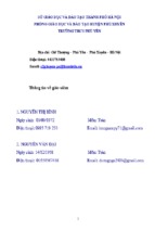
minor framing adjustments. The final towers installed for Saunders Lake are shown in Figure 3.
Figure 3. 240-kV Latticed Steel Towers
(Courtesy of Burns & McDonnell)
Structure Design – Harry Smith: Similar to those in the Saunders Lake sub-development,
the existing structures near the new Harry Smith substation drove structure type selection for
new lines installed nearby as part of SWEATD. The existing structures near the new Harry Smith
substation were steel H-frames and the new transmission structures at Harry Smith were
designed to match the configuration. The existing 240-kV H-frame line would be segmented
with an in-and-out tap to the new Harry Smith substation, so two new H-frame circuits would
run parallel to each other as single-circuit 240-kV lines. While this arrangement required more
ROW than ideal, AltaLink engaged with landowners to identify optimal placement of structures
on their properties. The H-frame structure type also allowed the project team to minimize
structure heights and meet the adjacent airport requirements as previously discussed.
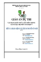
The Harry Smith sub-development also used unique triple-circuit structures, shown in Figure
4. Part of the scope of the Harry Smith sub-development included cutting in to the existing Stony
Plain-to-Acheson transmission line to create a single-circuit connection between the new Harry
Smith and Stony Plain substations and a double-circuit connection between the Harry Smith and
Acheson substations. While various routes and configurations were investigated, during project
development the team identified an opportunity to minimize landowner impact by combining all
three circuits on one structure and one connection point to the existing transmission line.
© ASCE
6
Downloaded from ascelibrary.org by RMIT UNIVERSITY LIBRARY on 01/03/19. Copyright ASCE. For personal use only; all rights reserved.
Electrical Transmission and Substation Structures 2018
7
Figure 4. 138-kV Triple-Circuit Tubular Steel Poles
(Courtesy of Burns & McDonnell)
Line
Volt.
(kV)
#
Ckts
Table 3- SWEATD Structure and Foundation Types
Structure
Structure
Conductor Type
Foundation Types
Framing
Material
Type
1
266 kcmil ACSR
Partridge
477 kcmil ACSR
Hawk
138
2
477 kcmil ACSR
Hawk
1033 kcmil ACSR
Curlew
138
3
240
240
138
Wood & Steel
Direct Embedment
Helical Can
Drilled Shafts
Monopole
Steel
Direct Embedment
Helical Cans
Drilled Shafts
1033 kcmil ACSR
Curlew
Monopole
Steel
Drilled Shafts
Helical Grillage
1
2x1033 kcmil Curlew
ACSR
H-Frame
Steel
Helical Cans
Helical Grillage
2
1590 kcmil ACSR
Falcon
Lattice
Tower
Steel
Helical Grillage
Monopole
While the triple-circuit structure minimized the number of structures and negotiations with
landowners, it introduced additional challenges. From a maintenance perspective, the structure
configuration introduced increased risk and complexity. Any energized maintenance work
performed on the upper circuits would require additional precautions to avoid the circuit below.
Reliability was also a concern with the triple-circuit design. By grouping three circuits together,
a failure of a single structure would remove three circuits from operation. As shown in Table 2,
the AESO reliability requirements do not address a triple-circuit design. The project team used a
© ASCE
Downloaded from ascelibrary.org by RMIT UNIVERSITY LIBRARY on 01/03/19. Copyright ASCE. For personal use only; all rights reserved.
Electrical Transmission and Substation Structures 2018
75-year return period for developing loading requirements to mitigate the risk associated with the
triple-circuit structure.
The project team expected the ground-line reactions for the triple-circuit structure to be
substantially higher than the reactions associated with a double-circuit structure of similar height
due to the addition of the “underbuilt” third circuit and the more severe loading requirements
associated with the 75-year return period loads. Once structure designs were completed,
however, the magnitude of the impact of the additional third circuit was more extreme than
anticipated. The ground-line moments associated with the triple circuit structures were almost
double the ground-line moments associated with a double-circuit structure of the same height.
This increase in ground-line reactions limited the types of foundations that could be used to
support the triple-circuit structures.
Foundation Design: The predominant drivers for the selection of foundation types were
installed cost, soil conditions, magnitude of loads, and restrictions to the size of the final
foundation footprint. Table 3 contains a list of the structure and foundation types used within
each sub-development. The geotechnical investigation revealed the presence of sand layers of
varying thicknesses interspersed with clay layers creating very soft subsurface conditions. There
were also many areas with high water tables. These soil profiles presented complications with
sloughing and seepage during excavation work.
Figure 5. Helical Can Installation
(Courtesy of Burns & McDonnell)
Direct Embedment: Since direct-embedded structures can minimize foundation cost and
have a small footprint, the project team used them as often as possible. Early in the project, a
desktop analysis was performed to determine where direct-embedded foundations were feasible.
Throughout the project process, proposed locations for direct-embedded foundations were often
re-evaluated for suitability. As the project moved into construction, the on-site crews noted that
soil conditions in some locations were poorer than anticipated. An early spring thaw also caused
site conditions to worsen. This change in conditions led the project team to determine that a
number of locations originally identified as suitable for direct embedded foundations would
require the additional support of helical cans.
Helical Cans: When a structure could not be direct embedded, the first alternative
considered was a helical can. Helical cans, also referred to as bucket piles, are commonly used in
© ASCE
8
Downloaded from ascelibrary.org by RMIT UNIVERSITY LIBRARY on 01/03/19. Copyright ASCE. For personal use only; all rights reserved.
Electrical Transmission and Substation Structures 2018
Alberta. They provide additional support for structures that may not require substantial
foundations like drilled shafts or grillages, but cannot be direct embedded. A helical can is
comprised of a helical pile base and a hollow upper section, as shown in Figure 5. Once the
helical cans are screwed into the ground, poles are embedded into the hollow upper section and
backfilled. The helical can foundation has a small footprint that allowed it to be used adjacent to
and parallel to roads. The largest bucket diameter used on the project was less than the 2-meter
maximum foundation size. The piles could also be bolstered with additional battered piles to
increase capacity if required.
Helical Grillages: The helical grillage foundations used for the project consisted of multiple
helical piles configured in an array. The individual helical piles were then connected to a grillage
comprised of wide flange steel members. This grillage connected to either latticed steel or
tubular steel structures via various baseplate adapters or transition plates. The footprint for most
helical grillage foundations exceeded the 2-meter limit, so the use of these foundation types was
limited to structures located on the ROW and not the road allowance. If a grillage was needed on
a structure located in the road allowance, the project team opted to bury the grillages as shown in
Figure 6. To accommodate burial, the foundation design was modified to consider the added soil
pressure on top of the grillage structure. The depth of the grillage also needed to be below the
frost depth, so extension bridges were used to connect the structure baseplate to the grillage
attachment point. Figure 6 shows the construction crew lifting the extension bridge into place on
a subgrade helical grillage foundation.
Figure 6. Buried Helical Grillage Installation
(Courtesy of Burns & McDonnell)
Drilled Shafts: While some portions of the project alignments could accommodate burying
large helical grillage caps to minimize permanent above-ground land impacts, locations such as
structure installations adjacent to roads could not. Drilled-shaft foundations are not commonly
used in Alberta due to the soil conditions, cost of concrete, and distance to construction sites
from batch plants. However, the SWEATD project was close enough to Edmonton that drilledshaft foundations were an economically viable option in some situations. Due to the soil
© ASCE
9
Electrical Transmission and Substation Structures 2018
Downloaded from ascelibrary.org by RMIT UNIVERSITY LIBRARY on 01/03/19. Copyright ASCE. For personal use only; all rights reserved.
conditions determined from the geotechnical investigation, foundation installation procedures for
the project included the use of temporary casing, permanent partial casings, and permanent fulllength casings. The smaller footprint of drilled-shaft foundations, compared to those of the
helical grillage foundations, helped support permitting compliance. Drilled shafts were used
primarily on the triple-circuit portion of the Harry Smith sub-development and on heavily loaded
dead-end structures located within the road allowance or alongside roadways.
CONCLUSION
The expanded region, multiple voltages, loading requirements, and construction challenges
made SWEATD a more complex project than typical. With a diligent plan of execution and
coordination and a design offering a wide range of options to tackle challenges, the project team
was able to keep construction efforts on schedule. The SWEATD project was energized in
December 2017, providing the necessary infrastructure for expected growth in Edmonton,
Alberta.
REFERENCES
Alberta Electric System Operator. “South and West of Edmonton Transmission System
Development Newsletter.” AESO Grid. Accessed February 1, 2018.
https://www.aeso.ca/assets/Uploads/SW-Edmonton-Newsletter-WEB.pdf.
Alberta Reliability Standards. Alberta Standard. Calgary, Alberta. Alberta Electric System
Operator. Accessed April 27, 2018. https://www.aeso.ca/rules-standards-and-tariff/albertareliability-standards/complete-set-of-standards/.
Alberta Electric System Operator. (June 2012) AESO Long Term Transmission Plan.
https://www.aeso.ca/downloads/AESO_2012_LTP_Sections_1.0_to_5.0.pdf
© ASCE
10