Erythrocyte Sedimentation Rate Analyzer
OPERATOR’S
MANUAL
Cat.112-00101
Operator’s Manual
iSED®
Erythrocyte Sedimentation Rate Analyzer
Cat. 112-00101
ALCOR Scientific Inc.
20 Thurber Boulevard
Smithfield, RI 02917
WWW.ALCORSCIENTIFIC.COM
Authorized Representative
EMERGO EUROPE
Molenstraat 15
2513 BH The Hague
THE NETHERLANDS
Phone: (31) (0) 70 345-8570
Fax: (31) (0) 70 346-7299
Dear iSED® Customer,
ALCOR Scientific would like to welcome you into the world of fast, efficient and accurate erythrocyte
sedimentation rate (ESR) results. With our welcome, we have provided you a packet of information to
get you started. We hope this information will make using the iSED even easier. Please find enclosed:
iSED Quick Reference Guide
This Quick Reference Guide includes simple setup and operating instructions.
Warranty Card
The instrument is backed by a One (1) Year Warranty. In order to assure coverage, you must activate
your Warranty by filling out the warranty card included with your instrument, and mailing it back to
ALCOR. The serial number label is located on the rear panel of the analyzer. Please see the last page
of the Operator Manual for more information and instructions.
ALCOR Scientific offers Technical Support Monday through Friday 8:30am-5:00pm EST (excluding all
US Federal Holidays) to help service you in the quickest way possible. The Technical Support Team can
be reached by any of the following:
Toll Free:
(800) 495.5270 (USA Only)
+1 (401) 737.3774
Fax:
+1 (401) 737.4519
Mail:
ALCOR Scientific Inc.
20 Thurber Blvd
Smithfield, RI 02917 USA
Email:
[email protected]
Please do not hesitate to contact ALCOR or your authorized ALCOR distributor if you have any
questions regarding any of the information found in this manual.
We thank you for selecting ALCOR products and look forward to serving your laboratory!
Best Regards,
ALCOR Scientific Support Team
ii
TABLE OF CONTENTS
Symbols Reference
The following is a list of symbols and their meaning used on the instrument, consumables and
accessory labeling.
Symbol
Meaning
Instrument satisfies requirements of European directive on in vitro diagnostic medical
devices (98/79/EC)
Date of manufacture
Manufacturer
Serial Number
In Vitro Diagnostic Medical Device
Product/Reference number
Fuse Rating(located on serial number label, replace with same value and type)
AC Single Phase Alternating Current
Consult instructions- refer operator to the instruction manual for additional information
Temperature limitation –Indicate storage requirements range
WEEE: Disposal of Waste Electrical and Electronic Equipment
Biological Hazard: Universal precautions should be followed
Caution: Moving Parts
Caution: Sharp Needle
Warning: Consult operator manual and observe safety warnings
Caution: May Cause Electrical Shock
Caution: Object is heavy. Use care and/or assistance in lifting
1.
iii
TABLE OF CONTENTS
INTENDED USE……...…………………………………………………………………... 6
1.
Methodology……………………………………………………………………………... 6
2.
2.1 History
2.2 Comparison with Existing methods
2.3 Method Limitations
Principle of Procedure………………………………………………………………..... 7
3.
General Information…………………………………………………………………….. 8
4.
4.1 For In Vitro Diagnostic Use
4.2 Notes, Precautions, Warnings and Biological Warnings
4.3 Precautions and Safety Information
4.4 Sample Requirements
4.5 Tube Requirements
5.
Tube
Instrument Overview……………………………………………………………………. 11
5.1 Features
5.2 Parts Identification
5.3 Consumables
5.4 IWASH Fluid
6.
Unpacking and Installation……...……………………………………………………. 13
6.1 Unpacking the Instrument
6.2 Contents of Box
6.3 Power Connection
6.4 RS-232 Connection
7.
Start-Up……………………………………………………………………………...……. 15
7.1 Icon Legend
7.2 Touch Screen Menus
7.3 Programming Date and Time
8.
Operating Instructions…………………………………………………………………. 17
8.1 Patient Identification
8.2 Auto ID Procedure
8.3 Manual Data Entry for Barcoded Tube
8.4 Manual Data Entry for Non-Barcoded Tube
8.5 Format of Automatically Assigned Identification
9.
Sample Collection………………………………………………………………………. 21
9.1 Compatibility with CBC Collection Tubes
9.2 Collection Procedure
10.
Simplified Procedure Outline…………………………………….............................. 22
11.
Calibration………………………………………………………………………………... 22
12.
Limitations of Procedure………………………………………………………………. 22
iv
TABLE OF CONTENTS
13.
Output
……………………………………………………………............................... 22
13.1 Expected Values
13.2 Performance
13.3 Results Format
13.4 Printed Results with Error Message
13.5 Reprinting of Results
13.6 Review Results
14.
Smart Cards ……………………………………………………………………………... 26
14.1 Downloading Credits from test Card
14.2 Low and Zero Credit Indicators and Alarms
15.
Routine Maintenance…………………………………………………………………… 29
15.1 Replacing Printer Paper
15.2 Replacing the Waste Bottle
15.3 Waste Bottle Full Indicators and Alarms
15.4 Replacing IWASH Bottle
15.5 IWASH Bottle Empty Indicators and Alarms
15.6 Replacing the Fuse
16.
System Status, Error Codes and Warning Messages…………………………….. 37
16.1 System Status Messages
16.2 System Warning Messages
16.3 System Error Messages
16.4 Sampling Error Messages
16.5 Print Out of Sampling Error Message
17.
Troubleshooting ………………………………………………………………………… 42
18.
Safety Precautions……………………………………………………………………… 43
18.1 General Considerations
18.2 Biological Waste
19.
Preventative Maintenance……………………………………………………………... 44
19.1 General Considerations
19.2 Preventative Maintenance/ Lifetime of Parts
20.
Technical Support………………………………………………………………………. 45
21.
Technical Specifications………………………………………………………………. 46
22.
Quick Reference…………………………………………………………………………. 47
23.
Warranty Information…………………………………………………………………… 48
v
1.
Intended Use
The iSED Erythrocyte Sedimentation Rate analyzer, is an automated
sedimentation rate analyzer which reports sedimentation rate in mm/hr.
It is a non-specific, quantitative result. Testing is done using
EDTA/whole blood samples, obtained by venipuncture. The instrument
can be used in hospital laboratories, clinical testing laboratories or
physician office laboratories by order of a physician to aid in assessing
the general health status of a patient.
2.
Methodology
2.1.
History
The discoverer of ESR in 1897 was a Polish physician, Edmund Faustyn Biernacki 1
(1866–1911). The most important conclusions from his observations were as follows: the blood
sedimentation rate is different in different individuals; blood with small amounts of blood cells
sediments faster; blood sedimentation rate depends on the level of plasma fibrinogen; in febrile
diseases (rheumatic fever included) with high levels of plasma fibrinogen the ESR is increased;
and in defibrinated blood the sedimentation process is slower. The findings presented by Biernacki
clearly showed the clinical significance of ESR.
In 1921, Swedish internist Alf Vilhelm Albertsson Westergren (1891–1968), presented a
similar description of the phenomenon of ESR 2 as those given by Biernacki and Swedish
hematologist, Robert Sanno Fåhraeus (1888–1968) 3. Westergren applied a blood sampling
method to the ESR test using sodium citrate as anticoagulant. Westergren also defined standards
for the ESR test and to which nearly all other automated ESR analyzers are referenced today. 4, 5
2.2.
Comparison with Existing Methods
Current ESR testing methods include manual, standing capillary tube type devices and automated
systems utilizing proprietary blood collection vials. These methods typically have test times of 20
to 60 minutes, may require open container blood transfer and minimum blood volumes of greater
than 1ml, which may result in extra blood drawing.
The iSED erythrocyte sedimentation rate analyzer is design to sample directly from the primary
(lavender top) 13 x 75mm, EDTA blood collection tube, automatically withdraw a test sample of
100µL volume and can produce a result in as little as 20 seconds, with appropriate prior
homogenization (ref. sec 13.2). The instrument’s micro-flow cell allows capture of the critical
kinetics of red blood cells aggregation in a highly controlled testing environment. This system
eliminates handling and the associated factors that can contribute to result variability.
The iSED reports results which have been correlated with the Westergren method.
1. Biernacki E. Die spontane Blutsedimentirung als eine wissenschaftliche praktisch-klinische untersuchungsmethode.Dtsch Med
Wschr 1897; 23: 769–72.
2. Westergren A. Studies of the suspension stability of the blood in pulmonary tuberculosis. Acta Med Scand 1921; 54: 247–82
3. Fåhraeus R. Über die Ursachen der verminderten Suspensionsstabilität der Blutkörperchen während der
Schwangerschaft. Biochem Z 1918;89:355–64
4. International Council for Standardization in Haematology (Expert Panel on Blood Rheology): ICSH recommendations for
measurement of erythrocyte sedimentation rate. J Clin Pathol 1993; 46:198-208
5. Thomas RD, Westengard JC, Hay KL, et al: Calibration and validation for erythrocyte sedimentation tests. Arch Pathol Lab
Med 1993; 117:719-72.
6
2.3.
Method Limitations 6
The erythrocyte sedimentation rate is a transient phenomenon confined to fresh blood. It is not a
hematic matrix component at the corpuscular or molecular level. The procedures used to
determine the ESR cannot be calibrated since they are susceptible to a variety of factors, e.g.
temperature, hematocrit, erythrocyte mean corpuscular volume, plasma viscosity, etc.
For this reason, it is possible to observe instrument performance deviations, compared to other
procedures, when the above variables are not taken into account.
Erythrocyte sedimentation remains a confusing, partly understood phenomenon and, clinically, is
a nonspecific reaction. It is highly recommended to perform other tests together with ESR since a
normal ESR value is not enough to exclude that the patient is not affected by a pathology.
Sample mixing is performed at the beginning of the analysis with the purpose of homogenizing
the sample. An inefficient homogenization can affect the results given by the instrument.
3.
Principle of Procedure 7
The ESR is a simple non-specific screening test that indirectly measures the presence of
inflammation in the body. It reflects the tendency of red blood cells to settle more rapidly in the
face of some disease states, usually because of increases in plasma fibrinogen, immunoglobulins,
and other acute-phase reaction proteins. Changes in red cell shape or numbers may also affect
the ESR.
When anticoagulated whole blood is allowed to stand in a narrow vertical tube for a period of time,
the RBCs – under the influence of gravity - settle out from the plasma. The rate at which they
settle is measured as the number of millimeters of clear plasma present at the top of the column
after one hour (mm/hr).The RBCs sediment because their density is greater than that of plasma;
this is particularly so, when there is an alteration in the distribution of charges on the surface of
the RBC (which normally keeps them separate from each other) resulting in their coming together
to form large aggregates known as rouleaux. Rouleaux formation is determined largely by
increased levels of plasma fibrinogen and globulins, and so the ESR reflects mainly changes in
the plasma proteins that accompany acute and chronic infections, some tumors and degenerative
diseases. In such situations, the ESR values are much greater than 20mm/hr. Note that the ESR
denotes merely the presence of tissue damage or disease, but not its severity; it may be used to
follow the progress of the diseased state, or monitor the effectiveness of treatment.
6. CLSI. Procedures for the Erythrocyte Sedimentation Rate Test; Approved Standard-Fifth Edition. CLSI document H02-A5. Wayne,
PA: Clinical and Laboratory Standards Institute; 2011.
7. McGill University, The McGill Physiology Virtual Laboratory, 200
4.
General Information
7
Read this manual carefully prior to operating the instrument.
This document is the operator’s manual for the instrument. It is intended to explain the
instrument operation in detail and can be used as a basis for training new operators. It is
an information guide and troubleshooting reference. Retain this manual for future use.
4.1.
4.2.
For In Vitro Diagnostic Use Only
Notes, Precautions, Warnings and Biological Warnings
The Operator’s Manual includes information and warnings. These need to be observed by the
operator in order to ensure safe operation of the instrument. There are four types of messages:
Notes, Caution, Warnings and Biological Warnings.
Notes
NOTE: Highlights important facts, gives helpful information and tips and clarifies
procedures.
Cautions
CAUTION: Electrical caution! Unplug before handling.
CAUTION: Important information on the proper operation of the instrument.
This information is crucial in preventing instrument damage and maintain the system.
Warnings
WARNING: Identifies potentially hazardous situations that could result in serious
injury to laboratory personnel.
Biological Warnings
WARNING: Universal precautions should be followed. Always wear gloves to prevent
exposure to pathogens.
4.3.
Precautions and Safety Information
8
Please pay close attention to the instructions, notes and symbols as well as the standard
laboratory practices outlined by your facility and local regulatory agencies.
Always keep a distance of at least 4 inches (10 cm) between the rear of the instrument
and the wall to allow for proper ventilation.
Do not use power frequencies or voltage other than those specified in this document.
Connection to an inappropriate power source may cause injury or fire.
Do not disassemble or modify the instrument. Doing so may cause injury and /or
instrument malfunction and void the warranty.
Place the instrument on a stable and level surface free of vibration. Failure to do so may
cause injury or malfunction of the unit.
CAUTION: To reduce the risk of electrical shock, do not remove any panel unless under
the direction of qualified personnel.
Do not block any ventilation openings.
Do not place instrument in water
Do not drop or throw the instrument
Operate the instrument on a dry, level surface
Do not move the instrument while specimens are processing
Plug the instrument into a grounded power source
WARNING: For continued protection against risk of fire and hazard, replace only with
the same type and rating fuse.
WARNING: The instrument’s main power switch is used as the main disconnect
device.
WARNING: Observe Universal Precautions. Discard contaminated materials
according to applicable regulations.
4.4.
Sample Requirements
9
Sample volume for testing is100μL whole blood (500μL dead volume)
Sample must be whole blood collected in K3-EDTA anti-coagulant tube
Sample must be neither coagulated nor hemolyzed (DO NOT mix vigorously!)
Sample should be tested within 4 hours of venipuncture (no more than 24 hours if refrigerated at
4°C)
Sample must be at room temperature for at least fifteen (15) minutes (if refrigerated)
NOTE: The instrument requires no additional or special sample preparation. As with all
anti-coagulant collection tubes, the sample should be well mixed after filling to help avoid
clotting or other aggregates that may alter ESR test results.
4.5.
Tube Requirements
13 x 75mm tube with pierceable cap
EDTA anti-coagulant (lavender top)
BD Microtainer® MAP Microtube
WARNING: Do not use if the tube stopper has been removed or is missing!
10
5. Instrument Overview
The rate at which red blood cells aggregate in whole blood has a direct effect on the resulting
sedimentation rate. Sedimentation rate is therefore an indirect representation of the rate of
aggregation. The iSED erythrocyte sedimentation analyzer uses photometrical rheology to
directly measure the aggregation of red blood cells. Once the sample is automatically processed
and in position, a sensitive optical detector in the iSED follows the progress of aggregation over
time. This produces a signalthat is a direct representation of the aggregation. The magnitude of
time-dependent change is correlated to the Westergren method.
5.1.
Features
100μL sample directly from closed primary EDTA tube (with or without barcode)
Minimum results time 20 seconds (with prior homogenization)
No disposables
Fully automated
Continuous Feed
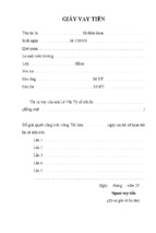
5.2.
Parts Identification
4
5
1
2
6
11
3
1
IWASH & Waste Bottle Compartment
2
Touch Screen
3
Sample Tube Return Tray
4
Printer
5
Sample Accessioning Port
6
Smart Card Reader
7
Power Connection Port
8
On/Off Switch
9
RS- 232 Connection Port
10
Fuse
11
Sample Ejection Port
9
10
8
7
11
10
5.3.
5.4.
Consumables
Item
Description
Reorder Part #
Printer Paper
57mm x 25mm (3 pack)
DS-05233
Test Card
Preloaded smart card for iSED, available
with tests in various quantities
112-02000 (2,000 preloaded tests)
112-05000 (5,000 preloaded tests)
112-10000 (10,000 preloaded tests)
112-20000 (20,000 preloaded tests)
iWASH Fluid
500 mL bottle with screw cap, pre-filled
with instrument iWASH (4 pack)
112-12-001
Waste Bottle
500 mL plastic waste bottle with screw
cap, (24 pack)
112-12-002
iWASH Fluid
The instrument uses Type 1 Ultra-Pure Water as the cleansing agent during the wash cycle.
The use of any other product could affect the performance of the instrument.
5.4.1. Specification
Type 1 Ultra-Pure Water: exceeds Clinical Lab Reagent Water (CLRW) specifications.
5.4.2. Continuous Operation Mode
It is recommended that the instrument remain on at all times and ready for use.
Should the instrument need to be powered off for any reason, run a wash cycle prior
powering off the unit.
NOTE: The instrument is programmed to perform self-cleaning after being idle for fifteen
(15) minutes following the last sample tested. The process takes approximately one (1)
minute and utilizes 3mL of iWASH for each wash cycle. Once completed, testing can
resume as normal.
12
6.
Unpacking and Installation
CAUTION: The instrument unit weighs 30 lbs. Use safe lifting techniques and proper
techniques when handling heavy objects. If necessary obtain assistance to safely lift
the instrument.
CAUTION: If using a utility knife, extend the blade to appropriate length to avoid
cutting any internal components.
All original packaging should be kept in the event the instrument needs to be returned for service
or warranty repair. For more information, please refer to the Warranty Information in the
Operator’s Manual, or call Customer Service at +1 401.737.3774.
6.1.
Unpacking the Instrument
Inspect the shipping container for any obvious signs of mishandling or shipping damage. If
damage is found, retain all package materials and immediately file a claim with the shipping
carrier.
1. Position the shipping container upright and open the top flap
2. Remove the accessory box on the right and set aside
3. Remove the box containing the power supply and the sample tray located on the foam insert
4. Remove the right side foam panel and then the left side foam panel
5. Remove the instrument slowly by lifting it vertically out of the shipping container
6. Place the instrument on a secure, flat surface
7. Remove the protective bag from the instrument
6.2.
Contents of the Box
1. iSED instrument (1)
2. Power Cord and Power Adapter (1 each)
3. Sample Collection Tray (1)
4. Pre-filled iWASH Bottle (1)
5. Waste Bottle (1)
6. Thermal Paper (1)
7. Spare Fuse (1)
8. Operator’s Manual with Warranty Information (1)
9. Product Registration Information card
13
6.3.
Power Connection
1. Connect the power cord to the power adapter
2. Insert the power adapter cord (with positive-lock connector) into the power connection port
located on the rear panel of the instrument
3. Place the instrument in its permanent operating location and plug the power cord into a
standard wall outlet
CAUTION: Always keep a distance of at least four (4) inches (10 cm) between
the rear of the instrument and the wall to allow for proper ventilation.
CAUTION: Place the instrument on a stable and level surface free of vibration.
Failure to do so may cause injury or malfunction of the unit.
CAUTION: Operate the instrument on a dry, level surface.
4. To power the unit on, press the On/Off switch located on the rear of the instrument
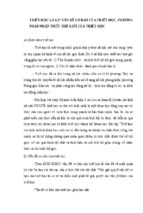
6.4.
RS-232 connection
The analyzer is equipped with an RS232 DB9 male connector for data transfer. The pin-out of the
connector is described in the following drawing.
For more information Document 112-09-020 Communication Protocol is available upon
request.
14
7.
Start-Up
7.1.
Icon Legend
All instrument functions can be accessed by using the touch screen. The following chart
identifies all icons and their function when pressed:
7.2.
Add Sample
Select
End/Stop
Return
Run wash cycle
Print
Service
Show Next Sample
Send to LIS
Show Previous Sample
Adjust Time/Date
Home (Measure Screen)
Add Sample
(Manual Patient
Data Entry)
Delete
Touch Screen Menus
The instrument is touch screen and all programming can be done by selecting or inputting data
on the following screens:
Home Screen:
15
Alpha and Numeric Key Boards:
7.3.
Programming Date and Time
To program the date and time on the instrument, the below procedure should be followed:
1. From the main screen, touch the
icon located in
the top right corner of the System Info frame
2. Keyboard will appear prompting the operator to input
Month data using the numerical equivalent, once
entered, touch the
icon to proceed
3. Enter the Day information and touch the
proceed
4. Enter Year information and touch the
5. Enter Hour information and touch the
proceed
6. Enter Minute information and touch
7. Touch the
icon to
icon to proceed
icon to
icon to proceed
icon to proceed
16
8.
Operating Instructions
NOTE: Always run a wash cycle prior to switching power OFF.
8.1.
Patient Identification
Barcoded Tubes: Patient samples are read and identified by the instrument’s internal barcode
reader automatically as they are loaded into the instrument. All common laboratory barcodes
are supported, including Code 39, UPC and Code 93 formats. Note barcode location range:
For instances when patient identification cannot be read by the internal barcode reader or there
is no barcode present the operator may enter data manually. For instructions on manually
entering patient data, please refer to page 19.
17
8.2.
Auto ID Procedure
All sample mixing, sample extraction, sample reading and sample disposal are handled
automatically by the instrument. Up to 20 sample tubes may be loaded into the sample wheel at
any given time. As each sample is processed (20 seconds), the sample tube is ejected from the
sample wheel and retained in the external sample collection tray. As soon as a sample is
ejected, another tube may be placed in the sample wheel.
1. Touch the
icon
2. The sample wheel rotates to position the next open slot
in the sample entry port
The onscreen information bar will report “waiting
sample” and the instrument will beep quietly for five (5)
seconds. As the five (5) second window draws to a
close, beeping will become faster.
3. Insert the barcoded tube with the barcode oriented to
the right. A red light will illuminate and a distinctive
beep will sound when the barcode is successfully
recognized
4. Automatic sample processing then begins
5.
Repeat Steps 2-4 until all samples have been loaded and/or all positions in the
sample wheel are occupied
NOTE: If the five (5) second window is missed, simply select the
to restart the sample scheduling process.
icon again
18
8.3.
Manual Data Entry for Barcoded Tube
The following procedure should be followed by the operator if the internal barcode reader is
unable to read the barcode information on the inserted tube.
1. Touch the
icon
2. The sample wheel rotates to position the next open slot
in the sample entry port
3. Insert the tube, the instrument will try and read the
barcode, if unable the operator will be prompted to
enter patient identification data manually using the
alphanumeric keyboard
4. Remove tube from sample wheel to allow for a visual
tube identification to input patient data (Optional)
5. Patient information must be recorded in one (1) or
more of the following data fields:
-
Alphanumerical ID
Patient’s First Name
Patient’s Surname
6. Touch the
information
icon to skip a data field or to confirm entered
7. Sample processing will begin once patient data has been entered
NOTE: (For tubes removed from sample wheel) If patient information data is not
entered within ten (10) seconds from the last pressed key, the loading process will
abort and the operator will restart the loading process for that tube.
NOTE: (For tubes not removed from the sample wheel) If patient information is not
entered within ten (10) seconds from the last pressed key, the instrument will
automatically assign an identification number. See page 20 for information on the
format for identification number(s) automatically assigned by the instrument.
19