Mô tả:
XÚC TÁC SỬ
SỬ DỤNG TRONG NHÀ MÁY
LỌC DẦ
DẦU DUNG QUẤ
QUẤT
By Nguy
Nguyễ
ễn Huỳnh Hưng Mỹ
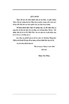
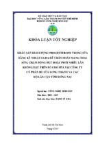
SƠ ĐỒ CÁC PHÂN XƯỞNG CÔNG NGHỆ CỦA DQR
LTU
Stabilizer
Gas Plant
Propylene
Propylene
Mixed LPG
LPG
ISOM
NHT
CCR
Treated Kerosene
C4’s
Isomerates
Reformates
RFCC Naphtha
Gasoline
Jet A1 /
Kerosene
CDU
KTU
Crude Tank
Farm (060)
PRU
Treated Kerosene
Auto Diesel
SPM
(082)
NTU
RFCC
LCO-HDT
Fuel Oil
Stt
1
2
3
Phân
xưởng
Tên xúc tác
CCR
Yêu cầu
o S-120
o Diethyl sulphide
o UOP
o Không tái sinh.
o ELF Atofina (Sing.)
Thay mới xúc tác
sau mỗi 4 năm
o Xúc tác thải làm
NL cho nhà máy
thu hồi kim loại.
o I-8
o I-8 Plus
o PURASPEC 2010
(xúc tác Methanator)
o PURASPEC 2443
o PerchlordEthylene
(xúc tác chloriding).
o UOP
o UOP
o Johnson Mathey
o R-134
o Diethyl sulphide
o UOP
Xúc tác thải nhà cung
o ELF Atofina (Sing.) cấp thu hồi để tái chế
NHT
ISOMER
Nhà cung cấp
o Johnson Mathey
o Thay mới xúc tác
sau mỗi 3 năm
o Xúc tác thải làm
NL cho nhà máy
thu hồi kim loại.
Stt
Phân
xưởng
4
RFCC
5
NTU
6
7
8
Tên xúc tác
Nhà cung cấp
AKZO NOBEL
COBRA RMR
AKZO NOBEL
ARI 100EXL
US FILTER
ACT 077
HR945
LCO-HDT HR448
DMDS (xúc tác
sulphiding)
ARI 100EXL
ARI 120L
KTU
MEA
(Methylethanolamine
- xúc tác chất mang)
ACT 077
HR945
LCO-HDT HR448
DMDS (xúc tác
sulphiding)
Axens
Axens
Axens
Yêu cầu
Xúc tác thải làm NL
sx xi măng, nhựa
đường
Xúc tác được tái sinh
sau mỗi 2 năm sử
dụng.
US FILTER
US FILTER
Union Carb
Axens
Axens
Axens
Xúc tác được tái sinh
sau mỗi 2 năm sử
dụng.
XỬ LÝ NAPHTA BẰNG HYDRO
(NHT)
Xử lý naphta bằng hydro - NHT
Xử lý naphta bằng hydro - NHT
Phân xưởng NHT được thiết kế để xử lý toàn bộ phân
đoạn Naphta từ phân xưởng chưng cất khí quyển.
Phân xưởng gồm một lò phản ứng xúc tác tầng chặt và
tuổi thọ xúc tác tối thiểu 2 năm.
Sản phẩm naphta từ phân xưởng xử lý Naphta bằng
Hydro được dẫn trực tiếp đến tháp tách Naphta.
Khí thoát ra từ phân xưởng NHT sẽ được đưa vào cụm
xử lý khí của phân xưởng RFCC và được làm sạch bằng
quá trình hấp thụ bằng amin.
Tên thương mại
S-120
Khối lượng riêng
850 kg/m3
Hình dạng
Viên vê
Kích thước
1/16”
Kim loại
Co, Mo
Chất nền
Oxít nhôm
Chu kỳ thay xúc tác
4 năm
Lượng xúc tác nạp
15.300 kg (18 m3)
8
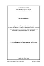
REFORMING XÚC TÁC LIÊN TỤC
(CCR)
CCR Catalyst used for DQR
• Catalyst type: R-134 (or R-234)
- Diameter: 1.6 mm
- Density: 560 kg/m3;
- Platinum: 0.29 wt-%
- Generated catalyst chloride: 1.1-1.3 wt-%
- Acid sites: Chloride
- Metal sites: Platinum
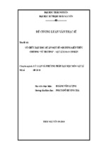
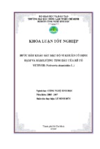
Properly Balanced Catalyst
Desired
(Pt)
Metal-Acid Balance
Increasing Metal
Function
Demethylation
(CL)
Increasing Acid
Function
Cracking
Dehydrogenation
Dehydrocyclization
Isomerization
CCR Catalyst Poisons Summary
Poison
Effects
Max. Level
Sulfur
Nitrogen
Metal
Acid
0.5 ppm in Feed
0.5 ppm in Feed
Water
Metals
High End Point
Acid
Varies
Stability
30 ppm in Recycle Gas
Varies
400°F (240°C)
CATALYST FOR PROCESSING
• Catalysts are used for isomerization to promote for
forming cacboni ion firstly. So, catalyst must be
acidic.
• Metals promote for hydrogenation reaction as Pt, Pd
CATALYST AND MERCHANDISE
MERCHANDISE CATALYST
PENEX-DIH
Catalyst for reactor 1, ton
21.1
Catalyst for reactor 2, ton
22.1
Adsorbent for drying feedstock, ton
7.6
Adsorbent for drying make-up gas, ton
2.6
Chloride compound, kg/day
165
CATALYST
• Catalyst characteristics
Catalysts consist of a mix of nickel and molibdenum
sulfides on an alumina support:
– A pre-treating catalyst is used first (HR-945) for
saturation of unsaturated compounds contained in
the cracked feedstock.
– The bulk of the desired reactions are performed
trough the HR-448 catalyst
• Method of catalyst regeneration: In-situ
• Cycle time for regeneration: 24 moths
• Catalyst life: 60 months
Process Engineering – Group 4
CATALYST
• Catalyst contaminant
– Inhibitors or activity moderators
• Carbon monoxide and
• Carbon dioxide
– Temporary poisons
• As, Sb, Pb
– Permanent poison
• Silicon
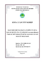
FIRST START-UP
•
Catalyst treatment
– H2 circulation
- Recycle Compressor Reactor Feed / Effluent Exchanger
(shell side) Reactor Heater Reactor Stripper Feed /
Reactor Effluent Exchanger (tube side), Reactor Feed / Effluent
Exchanger (tube side) Reactor effluent Air Cooler HP
separator Recycle Compressor KO Drum Recycle
Compressor
– Prewetting
• Slowly introduce the start-up gas oil into the reactor. 50%
flowrate is brought to reactor and 50% of flowrate is sent to
stripper.
• When gas oil is shown in HP separator, close recirculation line
and sent gas oil to slop.( to eliminate fine particles)
• Increase flowrate to 100% design throughput.
• Raise the pressure to the normal operating figure, keep reactor
beds at 80 -90ºC.
– Catalyst Sulfiding
CRACKING XÚC TÁC TẦNG SÔI CẶN
(RFCC)
- Xem thêm -