S7-200 Tip
PID-Instruction
SIMATIC
Group
6
Tip No. 53
S7-200 Tips
Topic
Using the PID-Instruction
CPUs required for this tip
CPU 210 CPU 212
CPU 214 CPU 215 CPU 216 OTHER
Overview
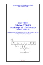
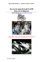
The following S7-200 program is an short example of how to use the PID instruction.
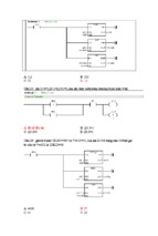
The PID instruction will be explained using an example of a water tank. The aim is to maintain a
constant water pressure and also keep the tank from being emptied.
pump with the
water supply
water level 75 %
Analog Output (0-10V) from PID process
B+,B- and C+,Care unused inputs
Analog Input (4-20mA) for PID PV
A+ A-
SIEMENS
SIMATIC
S7-200
SF
I 0.0
I 1.0
Q 0.0
Q 1.0
RUN
I 0.1
I 1.1
Q 0.1
Q 1.1
STOP
I 0.2
I 1.2
Q 0.2
I 0.3
I 1.3
Q 0.3
I 0.4
I 1.4
Q 0.4
I 0.5
I 1.5
Q 0.5
I 0.6
Q 0.6
I 0.7
Q 0.7
L+
CPU 216
B+ B-
EXTF
Vo L+ M
EM 235
AI 3x12Bit
AQ 1x12Bit
1 X
3 4
6ES7 214-1BC01-0XB0
M
Figure 53.1
Copyright 1997 by SIEMENS
Status: 10/97
page 1 / 13 c9b2fb4a5427046f57a912f708dd69dc.doc
Version 1.1
SIMATIC S7-200 customers have free use of the application tips. These tips are only a general approach to using the S7-200 with various applications.
Your specific application may be different. It is your responsibility to use the SIMATIC S7-200 properly in your applications.
S7-200 Tip
PID-Instruction
Tip No. 53
Hardware Requirements
1 S7-200 PLC
1 Expansion Module EM 235 Analog Combination AI 3/ AQ 1x 12 Bits
General Description
In this example, a water tank is used to maintain a constant water pressure. Water is
continuously being taken from the water tank at a varying rate. A variable speed pump is used to
add water to the tank at a rate that will maintain adequate water pressure and also keep the
tank from being emptied.
The setpoint for this system is a water level setting that is equivalent to the tank being 75% full.
The process variable is supplied by a float gauge that provides an equivalent reading of how full
the tank is and which can vary from 0% or empty to 100% or completely full. The output is a
value of pump speed that allows the pump to run from 0% to 100% of maximum speed.
The setpoint is predetermined and will be entered directly into the loop table. The process
variable will be supplied as a 4 to 20 ma analog value from the float gauge. The loop output will
be written to the analog output (0 to 10 V), which is used to control the pump speed. The span
of both, the analog input and analog output is 32,000.
NOTE: The Analog value (AIW0) can be averaged by an average subroutine, to filter the input
before the value is used as the PV. Refer tip no. 54 for details.
Only proportional and integral control will be employed in this example. The loop gain and time
constants have been determined from engineering calculations and may be adjusted as
required to achieve optimum control. The calculated values of the time constants are:
KC - 0.25
TS - 0.1 seconds and TI - 30 minutes.
The tank speed will be controlled manually until the water tank is 75% full, then the valve will be
opened to allow water to be drained from the tank. At the same time, the pump will be switched
from manual to auto control mode. A digital input will be used to switch the control from manual
to auto. This input is described below:
I0.0 - Manual/Auto control: 0 - manual, 1 - auto
While in manual mode, the pump speed will be written by the operator to VD108 as a real
number value from 0.0 to 1.0.
The following information documents the program and its operation as well as defining the
variables, subroutines and interrupt routines used by the program.
Subroutines:
SBR0 Initialization subroutine
SBR1 Subroutine to check, if an error occurred at the analog module
Copyright 1997 by SIEMENS
Status: 10/97
page 2 / 13 c9b2fb4a5427046f57a912f708dd69dc.doc
Version 1.1
SIMATIC S7-200 customers have free use of the application tips. These tips are only a general approach to using the S7-200 with various applications.
Your specific application may be different. It is your responsibility to use the SIMATIC S7-200 properly in your applications.
S7-200 Tip
PID-Instruction
Tip No. 53
Interrupt Routines:
INT 0 100 ms timed interrupt that invokes PID execution
Description of variables:
I0.0
Q0.7
Manual/Auto control
Error on the Analog module
The loop table is 36 byte long and the parameters in the V-memory table are all standard double
words (VD) The loop table has the following format:
Offset
Calculation
0
Process
variable
Setpoint
4
8
12
16
20
24
28
32
Format
Double word
- real
Double word
- real
Output
Double word
- real
Gain
Double word
- real
Sample time
Double word
- real
Integral time or Double word
reset
- real
Derivative time Double word
or rate
- real
Bias
Double word
- real
Previous
Double word
process variable
- real
Data
type
In
IN
In/Out
In
In
In
In
In/Out
In/Out
Description
Contains the process variable, which must be
scaled between 0.0 and 1.0
Contains the setpoint, which must be scaled
between 0.0 and 1.0
Contains the calculated output,
scaled between 0.0 and 1.0
Contains the gain, which is a proportional
constant. Can be a positive or negative number.
Contains the sample time, in seconds.
Must be a positive number.
Contains the integral time or reset, in minutes.
Must be a positive number.
Contains the derivative time or rate, in minutes.
Must be a positive number
Contains the bias or integral sum value
between 0.0 and 1.0
Contains the previous value of the process
variable stored from the last execution of the
PID instruction.
user
definable
NO
YES
NO
YES
YES
YES
YES
YES
NO
(Note: The basic address of the example program is VD100.)
VD100
VD104
VD108
VD112
VD116
VD120
VD124
VD128
VD132
process variable (PV)
, from the analog input AWI0
setpoint (SP)
output (M), contains the calculated output
gain (Kc), a proportional constant
sample time (Ts)
integral time (Ti)
derivative time (Td) or rate
bias (MX) or integral sum
previous process variable (PV N-1)
More information about the PID Instruction is provided in the S7-200 System manual. Basics of
Controlling with PID is explained in tip 32.
Information about the analog module is provided in the S7-200 System manual and in tip 34.
Copyright 1997 by SIEMENS
Status: 10/97
page 3 / 13 c9b2fb4a5427046f57a912f708dd69dc.doc
Version 1.1
SIMATIC S7-200 customers have free use of the application tips. These tips are only a general approach to using the S7-200 with various applications.
Your specific application may be different. It is your responsibility to use the SIMATIC S7-200 properly in your applications.
S7-200 Tip
PID-Instruction
Tip No. 53
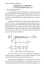
Program Structure
main program
Start
On the first scan: Initialization (SBR 0)
Set and enable time interrupts (INT 0)
On every scan: Check if the analog module has an error (SBR1)
Set Q0.7 if an error occured.
main program
End
Interrupt program
Start
Get the process variable value from the the anlog input word (AIW0),
scale value and store the converted value in the loop table.
In auto mode : execute PID-instruction
Update analog output
Interrupt program
End
Copyright 1997 by SIEMENS
Status: 10/97
page 4 / 13 c9b2fb4a5427046f57a912f708dd69dc.doc
Version 1.1
SIMATIC S7-200 customers have free use of the application tips. These tips are only a general approach to using the S7-200 with various applications.
Your specific application may be different. It is your responsibility to use the SIMATIC S7-200 properly in your applications.
S7-200 Tip
PID-Instruction
Tip No. 53
LAD (S7-MicroDOS)
STL (IEC)
program description and main program
// PID Example Program
1
2
3
│ SM0.1
0
├─┤
├────────────────────────( CALL
│
│
│ SM0.0
1
├─┤
├────────────────────────( CALL
│
│
├──────────────────────────────( MEND
│
)
LD
CALL
SM0.1
0
// On the first scan
// Call the initialization
// subroutine
)
LD
CALL
SM0.0
1
// On each scan
// Check if error at the analog
//module
)
MEND
// End the main program
Subroutines
// SBR0: Initialization (set and enable timed interrupt)
┌──────────┐
│ SBR: 0 │
└───┬──────┘
│ SM0.0
MOV_B───┐
5
├─┤
├───────────┬────────────┤EN
│
│
│
K100┤IN OUT├SMB34
│
│
└───────┘
│
│
ATCH────┐
│
├────────────┤EN
│
│
│
K0┤INT
│
│
│
K10┤EVT
│
│
│
└───────┘
│
│
│
└────────────( ENI )
│
6
├──────────────────────────────( RET )
SBR 0
LD SM0.0
MOVB 100, SMB34
// time interval (100ms) for timed
// interrupt
ATCH 0, 10
//Set timed interrupt to invoke
// PID execution
ENI
// Enable interrupts
RET
// SBR1: Check for errors at the analog module. If an error occurs set the Q0.7.
┌──────────┐
│ SBR: 1 │
└───┬──────┘
│ SMB8
KH19
Q0.7
8
├─────┤ == B ├─────┤NOT├─┬──────(
)
│
│
│
│
│
│
│
│
│ SMB9
KH0
│
├─────┤ == B ├─────┤NOT├─┘
│
│
9
├──────────────────────────────( RET )
Copyright 1997 by SIEMENS
Status: 10/97
SBR
1
LDB= SMB8, 16#19
// Check,
NOT
// if analog module is plugged in
LDB= SMB9, 16#0
// Check,
NOT
// if analog module has an error
OLD
=
Q0.7
// Error reading analog module
RET
page 5 / 13 c9b2fb4a5427046f57a912f708dd69dc.doc
Version 1.1
SIMATIC S7-200 customers have free use of the application tips. These tips are only a general approach to using the S7-200 with various applications.
Your specific application may be different. It is your responsibility to use the SIMATIC S7-200 properly in your applications.
S7-200 Tip
PID-Instruction
Tip No. 53
│
// INT 0: Interrupt routine - PID- Routine (timed interrupt for PID-execution).
┌──────────┐
│ INT: 0 │
└───┬──────┘
│ Q0.7
WXOR_DW─┐
11 ├─┤ / ├───────────┬────────────┤EN
│
│
│
AC0┤IN1 OUT├AC0
│
│
AC0┤IN2
│
│
│
└───────┘
│
│
MOV_W───┐
│
├────────────┤EN
│
│
│
AIW0┤IN OUT├AC0
│
│
└───────┘
│
│
DI_REAL─┐
│
├────────────┤EN
│
│
│
AC0┤IN OUT├AC0
│
│
└───────┘
│
│
SUB_R───┐
│
├────────────┤EN
│
│
│ KR+6400.00┤IN1 OUT├AC0
│
│
AC0┤IN2
│
│
│
└───────┘
│
│
DIV_R───┐
│
├────────────┤EN
│
│
│
AC0┤IN1 OUT├AC0
│
│ KR+25600.0┤IN2
│
│
│
└───────┘
│
│
MOV_R───┐
│
└────────────┤EN
│
│
AC0┤IN OUT├VD100
│
└───────┘
│ I0.0
PID─────┐
12 ├─┤
├────────────────────────┤EN
│
│
VB100┤TBL
│
│
0┤LOOP
│
│
└───────┘
│ SM0.0
MUL_R───┐
13 ├─┤
├───────────┬────────────┤EN
│
│
│
VD108┤IN1 OUT├AC0
│
│ KR+32000.0┤IN2
│
│
│
└───────┘
│
│
TRUNC───┐
│
├────────────┤EN
│
│
│
AC0┤IN OUT├AC0
│
│
└───────┘
│
│
MOV_W───┐
│
└────────────┤EN
│
│
AC0┤IN OUT├AQW0
│
└───────┘
│
14 ├──────────────────────────────( RETI )
Copyright 1997 by SIEMENS
Status: 10/97
INT
0
LDN
Q0.7
// If analog module is O.K.?
XORD AC0, AC0
// Clear the accumulator
MOVW AIW0, AC0
// save the analog value
DTR
AC0, AC0
// Convert 32-bit integer to real
-R
6400.0, AC0
// Adjust for 4 to 20 mA offset
/R
25600.0, AC0
// Normalize the PV
// value in the accumulator
MOVR AC0, VD100
// Store accu in the loop Table
LD
PID
I0.0
// When auto mode,
VB100, 0 // invoke PID execution
// Analog Output
LD SM0.0
MOVR VD108, AC0 // loop output to accu
*R 32000.00, AC0 // scale value in accu
TRUNC AC0, AC0
// Convert real to
// 32-bit integer
MOVW AC0, AQW0
// write the value to analog output
RETI
page 6 / 13 c9b2fb4a5427046f57a912f708dd69dc.doc
Version 1.1
SIMATIC S7-200 customers have free use of the application tips. These tips are only a general approach to using the S7-200 with various applications.
Your specific application may be different. It is your responsibility to use the SIMATIC S7-200 properly in your applications.
S7-200 Tip
PID-Instruction
Tip No. 53
Data Block DB1 (V Memory):
// initialize values
VD104
0.75
VD112
0.25
VD116
0.10
VD120
30.0
VD124
0.0
// setpoint = 0.75 = 75% full
// loop gain = 0.25
// sample time = 0.1 seconds
// integral time = 30 minutes
// no derivation action
Conversion Notes
To Convert from IEC STL to S7-Micro/DOS STL:
Add a ‘K’ before all non-Hex numerical constants (i.e. 4 K4)
Replace ‘16#’ with ‘KH’ for all Hex constants (i.e. 16#FF KHFF)
Commas denote field divisions. Use arrow or TAB keys to toggle between fields.
To convert an S7-Micro/DOS STL program to LAD form, every network must begin
with the word ‘NETWORK’ and a number. Each network in this Application Tip
program is designated by a number on the ladder diagram. Use the INSNW
command under the EDIT menu to enter a new network. The MEND, RET, RETI,
LBL, SBR, and INT commands each receive their own networks.
Line-Comments denoted by ‘//’ are not possible with S7-Micro/DOS, but NetworkComments are possible.
General Notes
The SIMATIC S7-200 Application Tips are provided to give users of the S7-200 some indication
as to how, from the view of programming technique, certain tasks can be solved with this
controller. These instructions do not purport to cover all details or variations in equipment, nor do
they provide for every possible contingency. Use of the S7-200 Application Tips is free.
Siemens reserves the right to make changes in specifications shown herein or make
improvements at any time without notice or obligation. It does not relieve the user of
responsibility to use sound practices in application, installation, operation, and maintenance of
the equipment purchased. Should a conflict arise between the general information contained in
this publication, the contents of drawings or supplementary material, or both, the latter shall take
precedence.
Siemens is not liable, for whatever legal reason, for damages or personal injury resulting from
the use of the application tips.
All rights reserved. Any form of duplication or distribution, including excerpts, is only permitted
with express authorization by SIEMENS.
Copyright 1997 by SIEMENS
Status: 10/97
page 7 / 13 c9b2fb4a5427046f57a912f708dd69dc.doc
Version 1.1
SIMATIC S7-200 customers have free use of the application tips. These tips are only a general approach to using the S7-200 with various applications.
Your specific application may be different. It is your responsibility to use the SIMATIC S7-200 properly in your applications.
S7-200 Tip
PID-Instruction
Tip No. 53
Tham khảo:
Chương trình S7 – 200 dưới đây chỉ là một ví dụ ngắn về cách sử dụng PID thông qua ví
dụ về điều khiển mức nước trong bể để vừa đảm bảo áp suất vừa đảm bảo nước trong bình
không bị cạn hết. Cấu trúc hệ thống như hình dưới đây:
Yêu cầu thiết bị điều khiển: 01 PLC S7 200/ CPU 216 trở lên và 01 khối EM 235 gồm có
3 đầu vào analog và một đầu ra analog 12 bít
Mô tả hệ thống:
Trong hệ thống này, một bể nước được dùng để khống chế áp lực nước không đổi.
Nước liên tục được lấy ra từ vòi với một tốc độ bất kỳ. Bơm được dùng để tăng thêm nước vào
bể với một tốc độ đủ để duy trì áp suất cũng như mức nước trong bình không hạ xuống quá
mức cho phép.
Giá trị đặt của hệ thống là mức nước (trong ví dụ này là 75% bể). Đại lượng đầu vào
của hệ thống là tín hiệu do một cảm biến đo mức đưa về thông qua đầu vào analog A+, A-. Tín
hiệu đưa về có thể thay đổi từ 4 – 20mA tương ứng với 0 – 100% mức đầy của bể. Tín hiệu ra
của hệ thống là tín hiệu điện áp có thể thay đổi từ 0 – 10 V dùng để điều khiển tốc độ bơm
tương ứng là 0 – 100% tốc độ định mức.
Giá trị đặt được quyết định bởi người sử dụng và được đưa trực tiếp vào quá trình.
Trong chương trình này, bộ điều khiển sử dụng hai thông số là P và I, không dùng đến D. Thời
gian lấy mẫu là Ts = 0.1 giây, KC = 0.25 và Ti = 30 phút.
Trước tiên, bể nước sẽ được tiếp đầy nước cho đến khi được 75%. Sau đó, van xả sẽ
được mở để lấy nước từ bể và cùng lúc bơm sẽ được chuyển từ chế độ điều khiển bằng tay
sang chế độ tự động.
Trong quá trình điều khiển bằng tay, tốc độ bơm được qui định bởi số thực lưu tại
VD108 nằm trong khoảng 0.0 tới 1.0.
Copyright 1997 by SIEMENS
Status: 10/97
page 8 / 13 c9b2fb4a5427046f57a912f708dd69dc.doc
Version 1.1
SIMATIC S7-200 customers have free use of the application tips. These tips are only a general approach to using the S7-200 with various applications.
Your specific application may be different. It is your responsibility to use the SIMATIC S7-200 properly in your applications.
S7-200 Tip
PID-Instruction
Tip No. 53
SBR0 là hàm thực hiện khởi tạo hệ thống.
SBR 1 là hàm thực hiện kiểm tra lỗi của khối analog.
Đầu vào I0.0 sẽ được dùng là tín hiệu khởi động hệ thống điều khiển tự động.
Đầu ra Q0.7 báo lỗi xảy ra ở module analog
Ngắt INT 0 thực hiện thuật toán PID mỗi 100 ms một lần
Bảng lặp dùng cho PID gồm có 36 byte và những thống số được đặt trong vùng nhớ V
và tất cả đều dùng là double word (VD)
Khoảng Thông số tính
cách
toán
so với
địa chỉ
bắt đầu
0
PV
4
SP
8
M
12
KC
16
TS
20
Ti
24
Td
28
Bias (MX)
32
PVN-1
Định dạng
Double word
- real
Double word
- real
Double word
- real
Double word
- real
Double word
- real
Double word
- real
Double word
- real
Double word
- real
Double word
- real
vào/ra
Mô tả
Người
dùng có
thể định
nghĩa
Tín hiệu về mức nước hiện tại trong bể, khoảng
0.0 – 1.0 tương ứng 0 – 100%
Giá trị đặt về mức nước trong bể, cũng phải
nằm trong khoảng 0.0 – 1.0
Giá trị tín hiệu ra, nằm trong khoảng 0.0 – 1.0
NO
YES
In
Hệ số khuếch đại P.
YES
In
Thời gian trích mẫu
YES
In
Thời gian tích phân.
YES
In
Thời gian vi phân
YES
In/Out
Tổng tích phân (bias MX or integral sum)
YES
In/Out
Giá trị mức nước đo được lần lấy mẫu trước
NO
vào
IN
In/Out
NO
Trong chương trình dùng địa chỉ bắt đầu của bảng là VD100
VD100
PV
, lấy vào từ AWI0
VD104
SP
VD108
M
VD112
Kc
VD116
Ts
VD120
Ti
VD124
Td
VD128
MX
VD132
PVN-1
Có thể tham khảo thêm về PID trong các tài liệu được cung cấp trong Hướng dẫn sử
dụng hệ thống S7 200 và các sách tham khảo khác.
Copyright 1997 by SIEMENS
Status: 10/97
page 9 / 13 c9b2fb4a5427046f57a912f708dd69dc.doc
Version 1.1
SIMATIC S7-200 customers have free use of the application tips. These tips are only a general approach to using the S7-200 with various applications.
Your specific application may be different. It is your responsibility to use the SIMATIC S7-200 properly in your applications.
S7-200 Tip
PID-Instruction
Tip No. 53
Lưu đồ thuật toán
Copyright 1997 by SIEMENS
Status: 10/97
page 10 / 13 c9b2fb4a5427046f57a912f708dd69dc.doc
Version 1.1
SIMATIC S7-200 customers have free use of the application tips. These tips are only a general approach to using the S7-200 with various applications.
Your specific application may be different. It is your responsibility to use the SIMATIC S7-200 properly in your applications.
S7-200 Tip
PID-Instruction
Tip No. 53
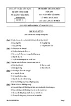
CHƯƠNG TRÌNH ĐIỀU KHIỂN
// PID
1
2
3
│ SM0.1
0
├─┤
├────────────────────────( CALL
│
│
│ SM0.0
1
├─┤
├────────────────────────( CALL
│
│
├──────────────────────────────( MEND
│
)
LD
CALL
SM0.1
0
// ON tại vòng quét đầu
// Gọi hàm khởi tạo hệ thống
LD
CALL
SM0.0
1
// Luôn luôn ON
// Gọi hàm kiểm tra lỗi của
// khối analog
)
MEND
// Kết thúc
)
Hàm chức năng
// SBR0: Khởi tạo hệ thống và khởi động ngắt thời gian
┌──────────┐
│ SBR: 0 │
└───┬──────┘
│ SM0.0
MOV_B───┐
5
├─┤
├───────────┬────────────┤EN
│
│
│
K100┤IN OUT├SMB34
│
│
└───────┘
│
│
ATCH────┐
│
├────────────┤EN
│
│
│
K0┤INT
│
│
│
K10┤EVT
│
│
│
└───────┘
│
│
│
└────────────( ENI )
│
6
├──────────────────────────────( RET )
SBR 0
LD SM0.0
MOVB 100, SMB34
// Thời gian ngắt là 100 ms
ATCH 0, 10
// Gọi chương trình ngắt thời gian (10) để
thực hiện thuật toán PID
ENI
// Chấp nhận hoạt động
RET
// Trở về chươn trình chính
// SBR1: Kiểm tra lỗi khối analog và báo lỗi bằng Q0.7
┌──────────┐
│ SBR: 1 │
└───┬──────┘
│ SMB8
KH19
Q0.7
8
├─────┤ == B ├─────┤NOT├─┬──────(
)
│
│
│
│
│
│
│
│
│ SMB9
KH0
│
├─────┤ == B ├─────┤NOT├─┘
│
│
9
├──────────────────────────────( RET )
│
SBR
1
LDB= SMB8, 16#19
// Nếu không có khối EM235 thì báo lỗi
NOT
LDB= SMB9, 16#0
// Nếu đã có EM235 nhưng có lỗi thì cũng
báo lỗi
NOT
OLD
=
Q0.7
// Error reading analog module
RET
Copyright 1997 by SIEMENS
Status: 10/97
page 11 / 13 c9b2fb4a5427046f57a912f708dd69dc.doc
Version 1.1
SIMATIC S7-200 customers have free use of the application tips. These tips are only a general approach to using the S7-200 with various applications.
Your specific application may be different. It is your responsibility to use the SIMATIC S7-200 properly in your applications.
S7-200 Tip
PID-Instruction
Tip No. 53
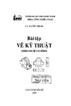
// INT 0: Thực hiện thuật toán PID
┌──────────┐
│ INT: 0 │
└───┬──────┘
│ Q0.7
WXOR_DW─┐
11 ├─┤ / ├───────────┬────────────┤EN
│
│
│
AC0┤IN1 OUT├AC0
│
│
AC0┤IN2
│
│
│
└───────┘
│
│
MOV_W───┐
│
├────────────┤EN
│
│
│
AIW0┤IN OUT├AC0
│
│
└───────┘
│
│
DI_REAL─┐
│
├────────────┤EN
│
│
│
AC0┤IN OUT├AC0
│
│
└───────┘
│
│
SUB_R───┐
│
├────────────┤EN
│
│
│ KR+6400.00┤IN1 OUT├AC0
│
│
AC0┤IN2
│
│
│
└───────┘
│
│
DIV_R───┐
│
├────────────┤EN
│
│
│
AC0┤IN1 OUT├AC0
│
│ KR+25600.0┤IN2
│
│
│
└───────┘
│
│
MOV_R───┐
│
└────────────┤EN
│
│
AC0┤IN OUT├VD100
│
└───────┘
│ I0.0
PID─────┐
12 ├─┤
├────────────────────────┤EN
│
│
VB100┤TBL
│
│
0┤LOOP
│
│
└───────┘
│ SM0.0
MUL_R───┐
13 ├─┤
├───────────┬────────────┤EN
│
│
│
VD108┤IN1 OUT├AC0
│
│ KR+32000.0┤IN2
│
│
│
└───────┘
│
│
TRUNC───┐
│
├────────────┤EN
│
│
│
AC0┤IN OUT├AC0
│
│
└───────┘
│
│
MOV_W───┐
│
└────────────┤EN
│
│
AC0┤IN OUT├AQW0
│
└───────┘
│
14 ├──────────────────────────────( RETI )
Copyright 1997 by SIEMENS
Status: 10/97
INT
0
LDN
Q0.7
// Nếu khối analog không có lỗi
XORD AC0, AC0
// Xóa AC0
MOVW AIW0, AC0
// Lấy giá trị đo được về mức nước PV
DTR AC0, AC0
// Chuyển đổi sang số thực 32 bít
-R 6400.0, AC0
// Chuyển đổi sang tín hiệu 4 – 20 mA
/R 25600.0, AC0
// Chuyển PV về giá trị thường dùng
MOVR AC0, VD100
// Lưu vào vùng nhớ
LD I0.0
// Chế độ Auto
PID VB100, 0 // Thực hiện PID với địa
chỉ bắt đầu là VB100
// Tín hiệu đầu ra analog
LD SM0.0
MOVR VD108, AC0 // Đưa ra AC0
*R 32000.00, AC0 // chuyển thang giá trị
TRUNC AC0, AC0
//Chuyển sang số nguyên 32 bít
MOVW AC0, AQW0
// Gửi ra đầu ra
RETI
// Trở lại chương trình chính
page 12 / 13 c9b2fb4a5427046f57a912f708dd69dc.doc
Version 1.1
SIMATIC S7-200 customers have free use of the application tips. These tips are only a general approach to using the S7-200 with various applications.
Your specific application may be different. It is your responsibility to use the SIMATIC S7-200 properly in your applications.
S7-200 Tip
PID-Instruction
Tip No. 53
Dữ liệu DB1 (V Memory):
// Khởi tạo
VD104
VD112
VD116
VD120
VD124
0.75
0.25
0.10
30.0
0.0
// SV = 0.75 = 75% full
// Kc = 0.25
// Ts = 0.1 seconds
// Ti = 30 minutes
// Td = 0
Copyright 1997 by SIEMENS
Status: 10/97
page 13 / 13 c9b2fb4a5427046f57a912f708dd69dc.doc
Version 1.1
SIMATIC S7-200 customers have free use of the application tips. These tips are only a general approach to using the S7-200 with various applications.
Your specific application may be different. It is your responsibility to use the SIMATIC S7-200 properly in your applications.
- Xem thêm -