ZJ - 4015D
TENSION CONTROLLER
MODEL
LE-40MTA-E
INSTRUCTION MANUAL
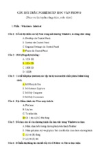
Introduction:
• This instruction manual describes the minimum necessary operations and functions for the
optimum adjustment of machines by using the LE-40MTA-E tension controller in Sections
1 through 5 taking "One-reel unwinding powder" shown below as an example.
Before start setting any systems, thoroughly read these five sections first.
• When mechanism other than "One-reel unwinding powder" is used, read Section 6 "Mechanism other than one-reel unwinding powder" for setting. For the basic items such as the
initialization, wiring as well as zero and span adjustment, read Sections 1 through 5.
• When using functions other than the above, read Section 7 "Use of extensive functions"
and after.
• Note that this instruction manual is applicable to system ROM version 3.00 or later.
Example of "One-reel unwinding powder "
Tension detector
Powder brake
Tension controller
Cautions on Safety
(Make sure to read this page before using the unit .)
To assure safety
• Make sure the user thoroughly read this instruction manual
before using the unit , and pay attention in assuring safety
while using the unit .
• The unit is manufactured under the severe quality control .
When a severe accident or loss is expected in the
equipment used due to failure of the unit , provide a backup
function or the fail -safe function in the system .
In this manual , cautions of safety are classified into "DANGER"
and "CAUTION".
off all the phases of the external power
DANGER Turn
supply before starting installation and wiring .
Otherwise, electrical shock or damage in the unit may
occur. Make sure to turn off all the phases of the
external power supply before starting installation and
wiring.
grounding ( grounding registance
DANGER Perform
100Ω or less).
Otherwise, electrical shock may occur. Perform
grounding ( grounding registance 100Ω or less) to the
2
unit using a wire of 2 mm or more, otherwise, electrical
shock may occur. Never share the grounding with a
strong electric system.
Never open the covers while the power is
DANGER supplied to the unit or when the unit is
operating.
Never supply the power to the unit nor operate the unit
while the main body cover and the terminal cover are
open. When the covers are open , a high voltage area
may be exposed and electrical shock may occur .
the unit is handled incorrectly , a
DANGER: When
dangerous situation may occur and the
possibility of death or serious injury is
expected.
CAUTION: When the unit is handled incorrectly , a
dangerous situation may occur and the
possibility of medium or slight injury is
expected or property damage exclusively
is expected.
Even an item is classified as "CAUTION", its contents are
important and it may lead to a serious result depending on the
situation. Make sure to observe every item .
Design the installation plan using the wire
DANGER size suitable to the current capacity .
Use the wire size suitable to the current capacity to
supply the power to the load . If a wire having smaller
current capacity is used,the insulation sheath will be
melted and insulation will become defective . In this
situation, electrical shock or a short-circuit may occur,
and fire may occur .
Set up the emergency stop circuit
DANGER independently of the product .
Otherwise, the unit may become out of order and an
accident may occur when malfunction occurs in the
tension controller. Make sure to assemble the
emergency stop circuit outside the tension controller .
use the unit in an atmosphere where
DANGER Never
inflammation or explosion can occur .
Otherwise, inflammation or explosion may occur .
Separate the wiring of the strong electric
CAUTION system from the wiring of the weak electric
system.
DANGER Never touch a switch with a wet hand .
Never touch a switch with a wet hand , otherwise,
electrical shock may occur.
Never drop cutting chips and wire chips
DANGER while screw holes are tapped and wiring
work is performed.
Damage , fume , fire, malfunction or others may be
caused in the unit .
DANGER Never modify nor disassemble the unit
Never modify nor disassemble the unit . Otherwise, the
unit may become defective or an accident such as fire ,
damage , etc . may occur.
CAUTION
Separate the wiring of the strong electric system from the
wiring of the weak electric system, and make sure that
noises are not superimposed on the wiring of the weak
electric system. Otherwise, the unit may not operate
correctly.
CAUTION Confirm the ambient enviroments .
Never install the unit with an enviroment where dusts , soot,
conductive dusts or corrosive gas is present or a place
exposed to high temperature , condensation or wind and
rain. Otherwise, the unit may be damaged , malfunction or
be deteriorated .
Do not use any unused terminals for any
CAUTION external lines.
Correctly connect the AC power cable to the specified
terminal, and do not use any unused terminals for any
external lines. Improper connection may seriously
damage the product .
• We shall not be responsible for any damage caused by repair , disassembly, modification, etc. performed
by a third party other than MITSUBISHI or a company specified by MITSUBISHI .
• The cautions on safety and the specifications described in the instruction manual are subject to change
without notice .
Table of Contents
1. Outline
1.1
1.2
7. Use of extensive functions
Outline of unit -------------------------------- 2
Panel configuration ------------------------- 3
7.1 Control of excessive sag or tension in
material during start and stop--------- 26
7.2 Control of excessive sag or tension in
material during acceleration and
deceleration -------------------------------- 27
7.3 Control of excessive winding tension
Internal reel diam eter taper control-- 28
7.4 External reel diameter taper control ----- 30
7.5 Change of control gains -------------------- 32
7.6 Output of contact when running out of
material -------------------------------------- 34
7.7 Use for machines with frequent inching
operation ------------------------------------ 34
7.8 Externally turns on or off control output -- 35
7.9 Setting of mechanical loss with two-reel
switching -------------------------------------- 35
7.10 Use of cut torque ---------------------------- 36
7.11 Reduction of variation in tension readout 36
2. Mounting and wiring (basics)
2.1
2.2
Caution on mounting ----------------------- 4
Wiring ------------------------------------------ 5
3. Operation
3.1
3.2
Setting and change of settings ---------- 6
Overall flow of screen ---------------------- 7
4. Basics of adjustment and operation
4.1
4.2
4.3
4.4
Adjustment flow for trial operation ------ 8
Initial setting ---------------------------------- 8
Adjustment of zero and span for tension
detector ------------------------------------- 10
Automatic operation ------------------------ 11
8. Use of external analog signals
8.1
8.2
8.3
8.4
8.5
8.6
5. Basic knowledge for operation
5.1 Entering Run/stop signals (use of MC1) --12
5.2 Use of stall setting
(output when operation is stopped)-- 13
5.3 Calling up engineer screen --------------- 15
5.4 Display of operator screen---------------- 16
9. Other functions
9.1 Records tension data------------------------ 40
9.2 Monitors input and output condition ----- 40
9.3 Returns all settings to initial factory
settings -------------------------------------- 40
9.4 Copies data settings to other controller --- 41
6. Mechanism other than
one-reel unwinding powder
6.1
6.2
6.3
6.4
6.5
6.6
6.7
6.8
6.9
Varies set tension ---------------------------- 37
Enters reel diameter data ------------------ 37
Varies stall ------------------------------------- 38
Varies taper ratio ----------------------------- 38
Varies new reel torque ---------------------- 39
Enters external tension data--------------- 39
Use of AC servo motor -------------------- 18
Use of E/P regulator------------------------ 19
Use for winding operation----------------- 20
Use for both winding and unwinding
operation ----------------------------------- 20
Feed reel control ---------------------------- 21
Simultaneous multi-reel control --------- 22
Powder unwinding, two-reel switching- 23
Powder winding, two-reel switching------ 24
Servo winding and unwinding,
two-reel switching ------------------------ 25
10. Inspection and maintenance
10.1
10.2
10.3
10.4
Initial inspection ----------------------------- 42
Maintenance --------------------------------- 42
Error display --------------------------------- 43
Unintended operation---------------------- 44
11. Specifications, miscellaneous
11.1
11.2
11.3
11.4
11.5
Input and output specifications---------- 46
External connection diagram ------------ 48
Various setting values --------------------- 49
Select items and analog data------------ 50
Outline dimensions and environmental
conditions ----------------------------------- 51
11.6 Supplement ---------------------------------- 52
1
1. Outline
1.1 Outline of unit
The tension controller LE-40MTA-E automatically controls the tension of a long material during unwinding,
use of the feed reel and winding, and is used together with the fine displacement tension detector.
The applicable actuators are powder clutch/brake, hysteresis clutch/brake, servo motor (torque mode), and
air clutch/brake.
• The tension setting and the manual operation torque usually used by the operator can be adjusted
easily using the trimmers provided on the panel.
• The diversified system parameters and operation parameters which must be set by the engineer before
operation can be set using the NUMERIC INPUT (increase/decrease) keys while checking the LCD
display provided on the panel.
• The automatic zero adjustment function and the span adjustment function for the tension detector as
well as the automatic control gain adjustment function for automatic adjustment are offered.
• The operation data can be read and written using the memory cassette FX-EEPROM- 4 (or-8) sold separately.
External
Potensiometer
Tension
detector
Tension
setting
Stall
New reel preset
Taper rate
Diameter ,Tension
AC85~264V
50/60Hz Power supply
Contact
Input
LE-40MTA-E
LE-40MTA-E
TENSION CONTROLLER
×10N MONITOR
SELECT
OUTPUT
ON/OFF
MODE
CURSOR
POWER
ON
AUTO
MANUAL
TENSION SET
MANUAL SET
5
ENTER
INC/DEC
OFF
Run/Stop
Reel change
Gain1
Stall memory reset
Gain2 Output remorte
Selected
Inching Cut torque
EXT Tension
P/N Power Amplifier Output
0~24V
5
PAGE
CANCEL
0
10
0
10
New reel preset
Power
Amplifier
Zero
Tension
Output
Powder clutch/brake
hysteresis clutch/brake
Recorder
E/P
regulator
Tension meter
Air clutch
brake
Servo motor
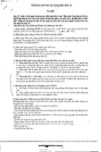
The above external devices may be connected to the input/output terminals of the tension controller.
The tension detector, actuator and some of the command input switches (those indicated with white letters on a black background) are mandatory. Other devices are connected as necessary.
2
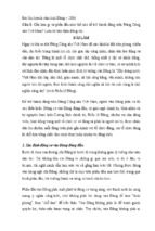
1.2 Panel configuration
The figure below shows the configuration of the panel of the tension controller LE-40MTA-E.
(5)
(6)
(7)
(8)
(9)
(4)
(10)
MONITOR
(3)
S ELE CT
OUTP UT
ON/ OFF
MODE
CURS OR
(2)
AUTO
POWER
TE NS ION S E T
ENTE R
OFF
CANCE L
INC/ DE C
P AGE
(25) (21) (20)
(24) (22) (19)
(23) (18)
(14)
(17) (16)
(15)
(13)
(12)
(7)
(8)
(9)
(10)
: POWER switch
: Power LED
: Output ON/OFF switch
: Output ON/OFF LED
: LCD display
: Bar graph
Upper :Tension monitor (%)
Lower :Target tension (%)
: Scale
: Seven-segment display
: Unit LED
: DISPLAY SELECTOR
Tension and output are
selected alternately.
Selection of kgf or N is
set by the parameter.
(11)
(12)
(13)
(14)
: Door open screw
: MANUAL mode switch
: Manual mode LED
: Manual torque set
trimmer
(15)
: AUTO mode switch
(16)
: Automatic mode LED
(17)
: TENSION SET trimmer
(18)(19) : Screen scroll keys
(20)(21) : Cursor contorol keys
(22)(23) : Numeric input keys
(24)
: CANCEL key
(25)
: ENTER key
1. POWER switch and OUTPUT ON / OFF switch
Turn on the POWER switch and the OUTPUT ON/OFF switch to light the LEDs provided on the upper
portion of the both switches.
(Note) Use OUTPUT ON/OFF switch or OUT REMOTE input without using the POWER
switch when the output is turned on and off.
• Allowable power switch cycles : 20,000 times
2. DISPLAY SELECTOR switch
The monitored operating tension value is always displayed in the bar graph on the upper right of the
screen.
Under the bar graph, the operating tension or control output is displayed in numeric.
The control output or the operating tension is displayed on the seven-segment display in the same way.
The type of contents displayed is changed every time the Tension/Output selector switch is pressed. The
type of contents displayed on the seven-segment display is indicated by the LED provided on the left
side of the selector switch.
The unit of tension (×10N or N) is specified by the setting of the parameter.
3. Automatic operation ( Basic operation )
Set tension (N)
Full scale tension
When the AUTO switch is pressed, the unit performs automatic operation. However, automatic control is not performed if the operation/
stop input is not turned on.
The tension set value changes from 0 to full scale value in accordance with the scale of the tension set trimmer of 0 to 10.
The full scale tension is set in the initial setting.
When the taper tension is controlled in accordance with the reel diameter, the tension set value subtracted by the taper tension is regarded
as actual target tension and used during automatic control.
3
2
4
6
Trimmer
8
4
6
Trimmer
8
Tension set
10
Right
60
80
100
Left
40
When the MANUAL switch is pressed, manual operation is available.
The control output of 0~100% can be obtained with the scale of the
manual torque set trimmer 0~10. (The output is 0~5V both in the servo mode and the powder mode.)
Control output (%)
4. Manual operation
0
20
(1)
ON
(11)
MANUAL
MANUAL S ET
(1)
(2)
(3)
(4)
(5)
(6)
0
2
Left
Manual set
10
Right
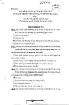
2. Mounting,connection and wiring
2.1 Caution on mounting
DANGER
• Never drop cutting chips and wire chips while screw holes are tapped and wiring
work is performed. Otherwise, damage, fume, fire, malfunction or others may be
caused in the unit.
• Make sure to turn off all the phases of the power supplies outside before starting
installation and wiring.
• Make sure to turn off all the phases of the power supplies outside also before attaching or removing the memory cassette.Otherwise, electric shock or damage in
the unit may occur.
• Make sure to attach the terminal block cover offered as an accessory to the unit
to prevent electrical shock before supplying the power after the wiring work.
CAUTION
• Never install the unit in a place with dusts, soot, conductive dusts or corrosive gas
or a place exposed to high temperature, condensation, wind or rain. Never install
the unit directly in a place in which vibration or impact is applied.
Otherwise, damage, malfunction or deterioration may be caused.
The tension controller can be installed on the floor, wall or panel surface.
Installed on floor
Installed on wall
Installed on Panel surface
4-M4×12
Mounting screw
TENSI O N CO NTRO LLER
×10N M O NI TO R
N
SELECT
%
O UTPUT
O N/ O FF
MO D E
CUR S OR
POWER
A U TO
MA N U A L
TE N S I O N S E T
ON
E N TE R
I N C/ D E C
O FF
MA N U A L S E T
16 8
LE -40 MTA - E
The unit is fixed
from rear face
with pressure
welding and
fixing screws.
P A GE
CANCEL
256
20 or less
172.5
36.5 or less
2~4
140
∗
FG on
metal plate
Perform the solid grounding in either
position marked with * in which the main
body mounting plate is not fixed.
Memory cassette
Screw hole dimensions for
mounting on floor or wall.
80±0.5
4 -M4
+3
244 -0.5
15 0±0.5
Panel cut dimensions for
mounting on panel surface.
232 ±0.5
Front door
Lead wire hole
Terminal block ( with cover )
The terminal block to connect external devices is provided inside the box .
When the front door is open, the terminal block can be seen. Pull the lead wire out of the
box from the lead wire hole provided on the lower portion of the box.
General description on wiring work
7.8 or
less
• Use crimp-style terminals whose dimensions are as shown in the figure on the left.
• The terminal tightening torque shall be 0.5 to 0.8 N•m (5 to 8 kgf•cm). Tighten the terminals securely so that malfunction will not be caused.
7.8 or
less
M3.5
• Perform Class 3 grounding to the analog I/O cables and the winding shaft pulse input
cable with shielded cables on the signal receive side.
• Never let the I/O cables pass through a duct together with other power cables. Never bind
the I/O cables together with other power cables.
• Generally, the allowable wiring length shall be 10 m or less to assure safety against noise.
General description on wiring work
4
2.2 Wiring
DANGER
• Set the emergency stop circuit outside the tension controller. If the tension controller performs malfunction, the unit may become out of order and an accident
may occur in the case in which the emergency circuit is built in the unit.
Connect the AC power supply to the terminals PSL and PSN as shown in the
figure above.
• If the AC power supply is connected to the I/O terminal or DC supply terminal, the
tension controller will be burn out.
Do not use the spare terminal for an external device. Otherwise, the unit may
be damaged. Perform the solid grounding to the ground terminal and FG using a
wire of 2mm2 or more.
• Never perform grounding together with the strong power system. Otherwise, malfunctionmay be caused.
The minimum connection reguired for the one-reel unwinding are as follows :
1. Connect AC100 to 240V 50/60 Hz power supply to power supply terminals PSL and PSN. The power
consumption is 400VA when the output of the power amplifier is at the maximum .
2. Perform the solid grounding to the ground terminals and metal plate according to Class D grounding.
3. Connect the tension detector.
4. If the actuator is a powder type, connect it between terminals P and N. If it is a torque-controllable
servomotor, connect it between terminals SA and SN. If it is an electric-pneumatic regulator of 420mA, connect it between terminals EAP and EAN.
5. Connect the Run/stop signals to the terminal MC1.
When using other functions, refer to Section 6 and after.
Power supply
PSL
AC100~240V
50~60Hz
PSN
LE-40MTA-E
P
Class D grounding
( 100Ω or less )
N
DC24v, 4A
Powder clutch/brake
Hysteresis clutch/brake
FG
Tension detector
(Right)
SA
GRR
WHR
SG
5V
SN
DC0~5V
Servo amplifier
Power amplifier
RED
BLK
GRL
WHL
Tension detector
(Left)
Run /
Stop
EAP
SG
EAN
4~20mA
E/P regulator
MC1
MCC
8V
Wiring of Tension Detector
• The figure on the right shows the connection diagram when the load is applied to the detector in
the compression direction.
When the load is applied in the tension direction, exchange the terminals GRR and WHR each
other as well as the terminals GRL and WHL each other.
• When one tension detector is used, connect it to the right side. And make sure to short-circuit the
terminals GRL and WHL on the left side.
5
3. Operation
3.1 Setting and change of settings
1. Selection of item on screen
When two or more items are displayed on the screen, one of them can be selected using the following procedure. The selected item is marked with " ", and held in the memory even while the power is interrupted.
When the menu items cannot be displayed on one screen, they can be scrolled and displayed using the
cursor control keys ( T S
).
T S
Select screen
T S
Flashing cursor is
placed at the top item .
Cursor
is moved
mark flashes
Flashing cursor is
placed at the top item.
mark flashes
ENTER
mark is lit.
Selection is
registered.
2. odification of set value on screen
When numeric will
be set for one item
onthe screen .
When numeric will be
set for two or more
items on the screen.
Select the desierd item using the cursor
control keys and ENTER key.
This selection procedure is not required for an
already selected item .
External analog input
Setting of items in use
Normal setting
Set by external trimmer
Set through panel
When indicated as "External" on
the screen, the setting changes
according to the external
controller setting to display on the
screen. (Setting can be made
without screen display .)
When the "External" indication
goes out , it indicates that the
external controller set value has
become smaller than the panel
set value.
Perform the tension setting
(TENSION SET) and manual
setting (MANUAL SET) using the
trimmer provided on the panel
(Entering of a numeric directly is
not possible .).
The set value is modified even if
the value is not displayed on the
screen.
The fixation of a
numeric input should
push the " ENTER "
key.
• When an item which can
be modified is selected,
under-cursor " _ " is
displayed in the numeric
input field.
Increase or decrease the
displayed value using the
numeric
input keys
, then press the
ENTER key for determination.
• When an item which can
Tension setting and manual
not be modified is selected,
setting are set by the trimmer , but
the under -cursor " _ " is
cannot set by the numeric input
not displayed.
key.
6
3.2 Overall flow of screen
The figure below shows the overall configuration of screen displays.
The data can be read in turn using the T and S keys.
Four major screens are available. Those are the initial setting screen, operator screen of usual operation,
engineer screen for system setting and memory cassette data transfer screen. This section shows the overall flow of the operator screen that is used in usual operation and the engineer screen. For other screens,
refer to the relevant sections.
Operator screens
(usual operation)
AUTO
switch
Initial setting
screens
Power on
for the
first time
Tension set
screen
T
S
T
Stall setting
(New reel setting)
Taper setting
T
MANUAL
switch
S
S
T
Manual set
screen
T
Confirm setting
S
Tension monitor 1
Tension monitor 2
Diameter monito
T
T
S
S
Password
screen
T
S
S
Instal mode only
Including all functions except the password setting on the initial setting screen.
Settings made during the initial setting can be changed as necessary.
Engineer screens (system parameters and operation parameters )
T
S
Switch
Tension
Unit
Control
reels
Number of
reels
Taper
Actuator
Stall
AI2
AI3
MC5
MC6
Filter
(Display)
Filter
(Output)
ZT
Zero
adjustment
Span
adjustment
Full scale
T
T
Start
and stop
Start T
Stop T
Stop G
Stop B
Out G
Reel change
Reel
Preset T
Cut torque
Mech.loss
Diameter
Others
Contact
monitor
Voltage
monitor
Set
inhibition
Gain
Gain
adjustment
Initialize
memory
T
T
7
T
T
T
4. Basics of adjustment and operation
4.1 Adjustment flow for trial operation
Carry out the following start-up adjustment as the preparatory step for the automatic operation.
(1)
(2)
(3)
Controller
* Initial setting
* Adjust tension detectors
Controller
installation and
wiring
Check the driving
system in manual
operation mode
See pages 8 through 10.
(4)
(7)
(5)
Check by automatic
operation
Operational check
Operating parameter
adjustment as necessary
See page 26 and after.
Completion of
adjustment
(6)
Check for abnormalities when
error occurs.
See pages 43 through 45.
4.2 Initial setting
Select the items using the W and X keys.
Press the [Enter] key to finalize the setting.
Then, switch the screens using the T and S keys.
When the setting of the items marked with "" is not changed,
switch the screens using the T and S keys without pressing the [Enter] key.
Power ON
L E - 4 0 M T A - E
T e n s i o n
C o n t r o l l e r
V e r .
V # . # #
C o p y r i g h t
M I T S UB I S H I
E L E C T R I C
CO RP .
When the power is turned on, the version display screen appears for a few seconds.
S T A R T
T HE
I N I T I A L
OR
C HA N G E
T O
M
The password "4095" is originally registered. When a password other
than this is used, enter the new password on the "Password registration"
screen and press the [Enter] key to register it. Both the newly registered
password and the original value "4095" are valid.
T
P A S S
W . E N T .
S E T→# # # # #
E N T E R
P A S S
T
T N S N . UN I T
S E L E C T
× 10 N
:
N
T E N T I O N
U N I T
T
8
WO R D
C N T L . P A R T
S E L E C T
UNW I ND
:
W I N D
R E E L
:
OR
RO L L
F E E D
FEED
T
R E E L
NUM .
S E L E C T
RE E L
1 R E E L
:
R E E L S
• When using the NRO
(new reel output), select
"Multi-reel" mode.
( See page 24 and after )
• Normally, the taper control is
not used for unwinding
control.
NUMB E R
T
T A P E R
O F F
S E L E C T
:
ON
T A P E R
T EN S I ON
CON T RO L
T P R . D I A .
I N T .
S E L E C T
:
E X T .
T A P E R
S I GN A L
T
INT
OFF
T
T A P E R MD .
S E L E C T
T A P E R
L I N E A R
:
NON - L I N E A R
MOD E
• This is to select whether to use the internal
signals of the tension controller or to
receive the external reel data to calculate
the reel diameter for the taper control.
Receiving the external reel diameter results
in better taper control accuracy.See page
28 for details.
T
D I A .
S E T
M I N . D I A→
S E T
D I AME T E R
# # # # mm φ
:
MA X . D I A→
# # # # mm φ
T
A C T U A T OR
P OW D E R
• Select "POWDER" when using
hysteresis or air clutch/brake.
S E L E C T
A C T U A T OR
:
A C
S E R VO MO T OR
• When using an AC servo, if it is
not desired to reverse the
direction of torque control
between resurrection and power
run, select "POWDER".
• This is to select the input
method of the stall settings.
See page 13 for the details
related to stall.
T
S T A L L
K E Y
MD .
S E L E C T
S T A L L
S E T : MA N . V O L .
S E T T NG
MOD E
Good to " MAN.VOL "
T
S T A L L
R S T
S E L E C T
S T A L L
MEMOR Y
MC 4 o n l y : MC 4 + OU T
SW .
R E S E T
MOD E
Good to " MC4+OUTSW "
T
A I 2
D I A .
S E L E C T
A I 2
:
S T A L L
:
NEW
AN A L OG
I NP U T
R . :
T A P E R
:
T N SN .
T
A I 3
D I A .
S E L E C T
A I 3
:
S T A L L
:
NEW
AN A L OG
I NP U T
R . :
T A P E R
:
T N SN .
T
MC 5
GA I N 2
S E L E C T
MC 5
I N P U T
:
I NC HNG
:
OU T
RMT . :
CU T
T RQ .
T
MC 6
GA I N 2
S E L E C T
MC 6
I N P U T
:
I NC HNG
:
OU T
RMT . :
CU T
T
9
T RQ .
• This is to select the input
method for resetting the stall
memory. The output on/off
switch can also control stall
memory reset.
• This is to select AI
(analog)
input and MC
(contact) input.
See page 26 and after for the
use of these functions.
These settings can be made on
screens other than the initial
setting.
It is all right if these settings are
made later on.
4.3 Adjustment of zero and span for tension detector
T
F U L L
S E T
S C A L E
S E T
→# # # # N
T E N S I ON
F U L L
:
× 1 0
: × 1
• This is to set the full-scale
tension (maximum
mechanical tension) and the
number of display digits.
For example, if desired to
have "50.0N" displayed,
select " 500 " and " × 0.1 ".
• Zero adjustment should be
made with the tare weight of
the detection reel and
without material.
• If unable to make zero
adjustment, check the
system referring to pages 43
and 45.
• If the tension full scale is
changed, carry out the
zero/span adjustment again.
S CA L E
:
× 0 . 1
T
Z ERO
T UN E
E X ECU T E
T E N S I ON
PU S H
< E N T E R >
OR
< C A N CE L >
T
ENTER
Z E RO
T UN I NG
CANCEL
Stand- by(for approximately 10sec)
Z ERO
T H E
S
Finished
Z ERO
T UN E
C OMP L E T E !
Error
T UN E
- - Z ERO
T U N I NG E RROR
D E T E C T I ON
RO L L E R
I S
T OO H
T
S P AN
T UN E
E X ECU T E
T E N S I ON
PU S H
< E N T E R >
OR
< C A N CE L >
T
ENTER
S P A N
T UN I NG
CANCEL
Stretch a string
in the center of
the roller.
S P AN
T UN E
S E T
T N S N . D T : T OW
X
S P AN
T UN E
WE I G H T
NUMB E R
:
ON L Y
OF
T N S N .
ON E
W ENTER
T
S U S P E N D
T E S T
→ # # # # N
NUMERIC
WE I GH T
S E T WE I GH T
T
ENTER
S P AN
T UN E
CON T .
T EN S I ON
S P A N
PU SH
< E N T E R >
OR
< C A N CE L >
T
ENTER
D E T E C TOR
T UN I NG ?
CANCEL
Finished
S
S P A N
T UN E
COMP L E T E !
L E F T → # # # # N
:
Error
S P AN
T UN E
- - S P A N
T U N I NG E R ROR
S P AN
T U N I NG
T A RGE T WE I GH T
I S
T
C H EC K
S E T
T H E
CH EC K
T H E
P A R AME T E R S
P U SH
< E N T E R >
DR I V I NG
P AR AME T
T
P A S SWO R D
S E T→# # # # #
ENTER
• Install the tension detectors
on both ends of the
detection reel as shown in
the left figure. For a short
detection reel, only one
tension detector may be
used. Use the following
screen to select one or two
tension detectors.
• Suspend weight W (N).
The weight should be a
static load as close to the
full-scale tension value as
possible
(Should be between 1 to 1/3
of the full scale).
• When, for example, a mass
of 10 kg is suspended,
multiply it by the
gravitational acceleration
(9.8) to make it 98N.
• Do not alter the load during
the adjustment. Otherwise,
the system may not be able
to adjust or may generate
an error.
• By the display unit setting,
the system shows the value
in the magnitude of "N" or
"×10N". When one tension
detector is used, the left
display shows zero. When
two detectors are used, the
left and right readings are
balanced.
• When unable to adjust the
span, check the system
referring to pages 43 and
45.
S • If an error message
appears, the system can
Error Message
not complete the
adjustment. Set the
E RS
system again.
• Initial setting completed.
The system setting screen
appears hereafter. Set the
S E T
NUMB E R
parameters as necessary.
10
4.4 Automatic operation
Having completed the steps described up to the preceding pages, the minimum necessary processes
shown in (1) and (2) below would be finished as the system controls the tension.
(1) Controller installation and wiring
(2) Initial setting (zero span adjustment of the tension detectors in particular)
Now, check the drive system in manual operation mode in step (3). Follow the procedure below.
• Press the power on/off switch to connect the system to the power supply.
• Press the manual mode switch. Use the manual torque controller to check the system operation.
Automatic mode switch
Display selection switch
Output on/off switch
LE-40MTA -E
× 10N
MODE
CURSOR
AUTO
POWER
MANUAL
TENSION SET
ON
ENTER
OFF
CANCEL
INC/DEC
Power switch
MONITOR
SELECT
OUTPUT
ON/OFF
MANUAL SET
Manual mode switch
PAGE
Tension controller
Manual torque controller
When completing the system check in manual operation mode perform operational check by the automatic
operation in step (4) following the procedure below.
• Set the tension controller. See page 18 for the operator screen.
T N S N .
S E T
S E T→
M N T . →
# # # # N
→
• Press the automatic mode switch to enter automatic mode.
• Turn on the MC1 contact input to start automatic operation.
This completes the basic adjustment for operation.
Where a different mechanism or other functions are used, refer to Section 6 and after.
If any problem in the operation, refer to Section 10.
11
5. Basic knowledge for operation
5.1 Entering Run / stop signals (use of MC1)
The minimum necessary preparation for tension control is described in "Adjustment flow for trial operation"
on page 10.
This section explains the use of start/stop (MC1) contacts essential to the step (4) operational check in automatic mode.
1. Run / stop (MC1 input)
------ Usually on during operation
• The contacts interlocked with the Run/
stop operation of the machine (such as
the feed motor Run/stop) are connected.
Press the automatic mode switch to enter automatic mode. With the MC1 input
made and after a lapse of time set in the
start timer, the automatic control will
start. See the figure on the right.
MC1 input
ON
OFF
OFF
Stop timer
Main shaft speed
Start timer
Control output
• When this input is turned off, the stop
gain and the stop bias become valid until
the stop timer times up. After that, the
stall values become valid.
(The start timer and stop timer will be
discussed later. See the next page for
more about the stall.)
Stall
Automatic control
Stall
2. Automatic mode indicator lamp
• The lighting conditions of the automatic mode switch, start/stop input (MC1) and the state of the
automatic mode indicator are as
the figure on the right.
Automatic mode
Operation command
(MC1)
Automatic mode LED
ON
OFF
OFF
Blink
ON
Light
Start timer
OFF
Blink
Extinguish
Stop timer
3. Connection
• Use a micro signal switch commensurate with DC8V
4mA as the input contacts. Connect the contacts
across MC1 and MCC.
Photo coupler
Operation / Stop
MC1
1.6kΩ
MCC
8V
12
5.2 Use of stall setting (output when operation is stopped)
Stall output is a constant torque given during the automatic control to the machine while it is stationary. At
this stage, the feedback control does not take place. This torque is the initial torque for the machine to start
with in the automatic control.
• When Run/stop signal MC1 is turned off to stop the material, the stall memory retains the control output
values used immediately before the stop. The system resumes the operation using the memorized
control output values to stabilize the tension in the material.
The stall memory function is a part of the basic functions, no need to be specially set.
• When changing materials, for example, the stall memory is reset to the output values appropriate to the
initial material diameter. These output values are called the stall setting value.
The system uses an EEPROM memory to keep the stall memory values even when the power supply is
turned off. No reset operation takes place even when the power supply is turned off or automatic or manual
modes switching is performed.
Internal
Internal
stall
stall setting
setting
External
stall setting
Large
Large side:
side:
Preferenced
Preferenced
Torque
Torquecontrol
controloutput
output
Memory
Memory
Reading
Reading
Tension
Tension detection
detection
Target
Target tension
tension
--
PP
AI3
AI4
Stall
Stallmemory
memory
Selection
Selection
of
of terminal
terminal
Stall
Stall setting
setting value
value
MC4
Stall memory
memory reset
reset command
command
0~100%
0~100% output
outputagainst
against0~5V
0~5V
SA
SA
EAP
EAP
Items
Items in
in square
square::Setting
Settingon
onpanel
panelsurface
surface
1. Resetting stall memory value
• Two methods are available to reset
the stall memory value as follows:
ON
ON
Operation input MC1
Stall memory
• An output on/off switch is used to reset the stall memory value.
• Stall memory reset input MC4 con- Main reel speed
tacts are used for reset.
In either case, the switch is normally Control output
Stall seting
turned on when the reel is changed.
Stall seting
value
value
• When the initial setting "MC4 + OUT.
Stall memory value
SW" at the "STALL RESET" screen is
selected (see page 9), the control MC4 input or
output on/off switch
output is switched from "ON" to
(On when reel is exchanged)
"OFF" by the output on/off switch on
the panel at the time of changing the
material. The stall memory value will
be preset to the stall setting value.
• When MC4 is kept "on" for approximately 0.5 second or longer, the stall memory value is preset to the
stall setting value.
2. Entering stall setting value
• The manual torque controller is used to set the stall setting value in the initial setting. Therefore, the
manual torque value will be the stall setting value (stall torque value) in the automatic control.
13
3. Connection
• To reset the stall memory externally, the MC4 contacts
are used.
• Use a micro signal switch commensurate with DC8V
4 mA as the input contact.
• If the stall memory reset input MC4 and MCC are
short-circuited, the stall output is always the same as
the stall setting value.
• If a signal interlocked with the reel shaft release signal
and shaft removal signal is connected to the MC4
contacts, the stall memory can be reset automatically
when changing the material.
Photo coupler
Stall memory reset
MC4
1.6kΩ
MCC
8V
4. Method of entering stall setting value without using manual torque controller
----------------A special use of stall function
• In addition to the method by the manual torque controller, following two methods are available to enter
the stall setting value.
• Setting by key input on the operator screen
• Setting by external analog input
• To change the stall setting value by key input on the operator screen, use the "STALL MD." screen with
”SWITCH" on the initial setting screen or the engineer screen.
S T A L L
K E Y
MD.
S E L E C T
S T A L L
S E T :
MA N . V OL .
S E T T N G
MOD E
Select "KEY SET ".
• To enter the stall setting value by key input on the operator screen, use the "STALL SET" screen.
S T A L L
S E T
S T A L L
# # # %
T N S N.
→ ## ##N
S ES TE T →
S E T→
# # # %
OU T P U T→
# # # %
• To change the stall setting value input by the external analog input setting, refer to page 40.
5. Resetting stall memory only by MC4
-------- A special use of stall function
• The system can be set so as to reset the stall memory value only by the MC4 contacts without using
the output on/off switch.
• Use the "STALL RST" screen within "SWITCH" on the initial setting screen or the engineer screen.
S T A L L
R S T
S E L E C T
S T A L L
M EMOR Y
MC 4 o n l y :
MC 4 + O UT
SW .
Select "MC4 only".
14
R E S E T
MO DE
5.3 Calling up engineer screen
• Follow this operation to make changes from the state of initial setting.
• Enter the password on the password screen. Press the enter key to enter the engineer screen.
Reel diameter
monitor or tension
monitor screen.
Complete
initial setting
T
T
P A S SWO R D
S E T
NUMB E R
S E T→# # # # #
Numeric input
4095
¾ Enter"4095" or the value
registered in the initial
setting as the password
(Refer to page 8.)
¾
ENTER
T
Error input
message
S
Enginneer screen
S E T T I NG
SW I T C H
W
S E L E C T
ME NU
B Y
CU R SOR
:
T E N S I ON
:
S T R T . S T P :
R E E L
S E T T I NG
S E L E C T
R E E L
C H G : M E N U
T
S
CHG :
X
ME NU
B Y
C UR SOR
:
O T H E R
:
GA I N
For setting of these items,refer to the initial setting.
Seting screen
T
Standard of volume set output
The control output by the manual torque and the stall setting are set
by the following standard .
Feed control
Manual
torque
N=
D
D
max
•
F
Feed control
× 100 N =
F max
~
D0
F0
Stall
N=
•
× 100 N =
New reel preset
F max
D max
Fmax =
F
F
max
× 100
~
F
F
max
× 100
Ratings torque of actuators
The maximum use torque of actuators
Dmax
D
F
D0
F
:
:
:
:
:
Maximum diameter
Diameter
Control tension
Initial diameter
Average drive tension
× The maximum drive tension
• Obtaining stall value and new reel torque by operating actual machine
Operate the machine in automatic control mode with the target tension . Display the
output on the output indicator (4-digit, 7-segment display ).
Read the output value where the reel diameter is close to the initial diameter . It is
recommended to use this value as the stall value .
15
5.4 Display of operator screen
The usual operations (setting operations) are performed on the following screen.
Automatic
Operation
Mode selected
• The bar graph in the upper right corner always
indicates the detected tension (%). The "100%"
indication corresponds to the full -scale tension.
Tension set
T N S N .
S E T
M N T . →
T N SN .
S E TS E T →
# # # # N M N→
T .
→
S E T → # # # . # × 10 N →
T
S
Stall set
S T A L L
S E T
S T A L L
S E TS E T →
# # # %
S E T→
# # #%
T
TN S
N
. →
# # #
# N
OU T P UT→
# # # %
S
• This displays the set
tension.
• The unit of tension such
as "×10N" and " N " and
the position of the
decimal point are
determined depending on
the parameter setting .
• This is to enter the stall
values .
Refer to pages 13 and 14
for more about the stall
functions.
When new reel and taper
functions are in use .
Manual
Operation
Mode selected
• Sets the operation torque
for the manual operation .
Refer to page 15 for the
guideline of setting .
Manual setting
M A NU .
S E T
M AN U .
S E T S E T→
# # # %
# # # %
MA N U .
S E T S E T→
S E T→
T
T N
S
N .
→
# #
# #
N
T N
S
N .
→#
#
# .
# × 10
N
# # # %
OU T P U T→
# # # %
• Displays the tension or
the output by the
tension/output select
switch on the panel.
S
Total tension monitor
T N S N . MN T .
T N S N . MT NA T
RG
. E T
→
T A RG E T
→
# # # # N
→ # # # . # × 10 N →
T
S
Tension monitor left and right
T N S N . MN T . L E F T →
# # # # N
T N S N . MN T
R .I LG EH FT →
T
→
# ## ## ## N
. # × 10 NT A
R
G
E
T
→
# #
# #
N
R I G H T → # # # . # × 10 N
T A R G E T → # # # . # × 10 N
T
• When carrying out the
taper control , the taper
ratio is taken into the
"target (target tension )"
value.
S
Use of reel diameter input
Password
screen
16
• This displays the left and
right tension
measurement . This
allows to check whether
the tension in the material
is balanced.
• The unit of tension (N or × 10N) and the decimal point position are determined by setting the parameter.
• The DISPLAY SELECTOR (TENSION /OUTPUT) switches over the tension display and output display.
• On the screen of Tension set, Stall set, New reel set, Taper ratio, the internal setting or the external setting
which is effective is displayed on the screen. When the external setting is effective, "EXT." is displayed on
the screen.
New reel set ( When multi-shaft mode is selected. )
N EW
R . S E T
N EW
# # #%
R . S E T S E T→
S E T→
# # #%
T
T N
S
N .
→
#
# #
#
N
OU T P U T→
# # #%
S
Linear taper set ( When taper is selected. )
T A P E R
S E T
T A P E R
# # #%
S E T S E T→
S E T→
# # # %
T N
S
N
. →
#
#
#
#
N
OU T P U T→
# # #%
Nonlinear taper set ( When non linear taper is selected.)
T A P E R
CN R 1
W
S E T
# # # # m m φ →
T P R . 1
# # # % :
C N R 2
# # # # mm φ→
T A P E R
S E T
T P R . 3
# # # % :
CN R 4
X
# # # # m m φ →
T P R . 4
# # # %
Reel diameter monitor (When reel diameter input is used .)
D I A . MN T .
A T. →
# # # # mmφ
D I A .D MI N
.
D I A . →
# # # # mmφ
T N
S
N .
→
# #
# #
N
O U T P U T→
17
# # # %
6. To use other than one - reel unwinding powder
6.1 Use of AC servo motor
The system is equipped with the SA-SN terminals for controlling an AC servomotor or a vector inverter motor that can control torque.
The SA terminal can be connected to some servo amplifiers for the simultaneous multi-reel operation.
1. Wiring (example)
Provide the torque command input of the servo amplifier with the following input.
During operation and during normal stop
: Torque command SA of the tension controller
Emergency stop
: Output from the braking torque controller
Provide the speed limit input of the servo amplifier with the following input.
During operation and during normal stop
: Upper speed limit setting
Emergency stop
: Set the speed limit input to zero.
Upper Limit
Torque Limit
Servo amplifier
Upper Limit
Speed Limit
LE-40MTA-E
SA
Torque command
Torque input
SN
EMG.stop
Speed Limit input
Normal opelation
2. Setting
• For the setting, use the "ACTUATOR" screen within "SWITCH" on the initial setting screen or the engineer screen.
• In servo mode, the control values of -100% to 100% correspond to the SA output of -5 to 5V. In powder
mode, the control values of 0 to 100% correspond to the SA output of 0 to 5V. The powder mode is
completely no problem if the torque is in one direction.
A C T UA T O R
P OW D E R
S E L E C T
A C TU A TO R
: A C
S E R V O
MO T OR
Select "AC SERVO MOTOR".
Handling of servo motor
Setting and changing servo
amplifier parameters
With the servo-on input terminal turned
off, turn on the servo amplifier power
supply. Change the settings of the
following parameters .
• Put the servo loop in torque mode .
• Set the system so that the servo
motor output torque is equal to the
rated torque when the 5V torque
command is issued.
For more details of the wiring and
setting, observe the servo amplifier
instruction manual .
Basic operation check
• Use the upper speed controller to set the speed limit
input . Enter the torque command while the tension
controller is in the manual operation . Then , check if
the motor rotates in the correct direction . Note,
however, that the unwinding motor rotates in the
correct direction when it reverses , because the
material during the unwinding operation pulls it .
• Check that the output torque is adjustable manually to
produce the specified torque even when paper is
running through the system .
In the manual operation , however , the dial readings of
zero to 10 on the manual torque controller correspond
to the output of 0 to 5 V in the manual operation .
18
- Xem thêm -