Downloaded from ascelibrary.org by RMIT UNIVERSITY LIBRARY on 01/05/19. Copyright ASCE. For personal use only; all rights reserved.
Structures Congress 2017
Bridges and Transportation
Structures
Selected Papers from the
Structures Congress 2017
Denver, Colorado
April 6–8, 2017
Edited by
J. G. (Greg) Soules, P.E., S.E., P.Eng
Downloaded from ascelibrary.org by RMIT UNIVERSITY LIBRARY on 01/05/19. Copyright ASCE. For personal use only; all rights reserved.
Structures Congress 2017
Bridges and Transportation
Structures
SELECTED PAPERS FROM THE STRUCTURES CONGRESS 2017
April 6–8, 2017
Denver, Colorado
SPONSORED BY
The Structural Engineering Institute (SEI)
of the American Society of Civil Engineers
EDITED BY
J. G. (Greg) Soules, P.E., S.E., P.Eng
Published by the American Society of Civil Engineers
Downloaded from ascelibrary.org by RMIT UNIVERSITY LIBRARY on 01/05/19. Copyright ASCE. For personal use only; all rights reserved.
Published by American Society of Civil Engineers
1801 Alexander Bell Drive
Reston, Virginia, 20191-4382
www.asce.org/publications | ascelibrary.org
Any statements expressed in these materials are those of the individual authors and do not
necessarily represent the views of ASCE, which takes no responsibility for any statement
made herein. No reference made in this publication to any specific method, product, process,
or service constitutes or implies an endorsement, recommendation, or warranty thereof by
ASCE. The materials are for general information only and do not represent a standard of
ASCE, nor are they intended as a reference in purchase specifications, contracts, regulations,
statutes, or any other legal document. ASCE makes no representation or warranty of any
kind, whether express or implied, concerning the accuracy, completeness, suitability, or
utility of any information, apparatus, product, or process discussed in this publication, and
assumes no liability therefor. The information contained in these materials should not be used
without first securing competent advice with respect to its suitability for any general or
specific application. Anyone utilizing such information assumes all liability arising from such
use, including but not limited to infringement of any patent or patents.
ASCE and American Society of Civil Engineers—Registered in U.S. Patent and Trademark
Office.
Photocopies and permissions. Permission to photocopy or reproduce material from ASCE
publications can be requested by sending an e-mail to
[email protected] or by locating a
title in ASCE's Civil Engineering Database (http://cedb.asce.org) or ASCE Library
(http://ascelibrary.org) and using the “Permissions” link.
Errata: Errata, if any, can be found at https://doi.org/10.1061/9780784480403
Copyright © 2017 by the American Society of Civil Engineers.
All Rights Reserved.
ISBN 978-0-7844-8040-3 (PDF)
Manufactured in the United States of America.
Structures Congress 2017
iii
Prreface
Downloaded from ascelibrary.org by RMIT UNIVERSITY LIBRARY on 01/05/19. Copyright ASCE. For personal use only; all rights reserved.
The Structures Congress
C
hass a robust tecchnical proggram focusinng on topics important too
Strucctural Engin
neers.
The papers in the proceeding
g are organizzed in 4 voluumes
ume 1 includ
des papers on
n Blast and Impact
I
Loadding and Ressponse of Strructures
Volu
Volu
ume 2 includ
des papers on
n Bridges an
nd Transporttation Structuures
Volu
ume 3 includ
des papers on
n Buildings and Nonbuillding and Sppecial Structtures
Volu
ume 4 includ
des papers on
o Other Strructural Enggineering Toppics includinng; Business
and Professional Practice, Natural
N
Disaasters, Nonsttructural Syystems and C
Componentss,
orensics
Educcation, Research, and Fo
Acknow
A
wledgm
ments
Prep
paration for the Structurres Congress required ssignificant tiime and efffort from thee
mem
mbers of th
he National Technicall Program Committeee, the Loccal Planningg
Com
mmittee. Mucch of the succcess of the conference
c
rreflects the ddedication annd hard workk
by th
hese volunteeers.
We would
w
like to thank GEIICO and Peaarl for Sponssoring the Congress procceedings andd
supp
porting the Structures Co
ongress in su
uch a generouus way.
The Joint Progrram Committtee would like
l
to acknnowledge thee critical suupport of thee
spon
nsors, exhibiitors, presen
nters, and mo
oderators whho contributted to the suuccess of thee
confference throu
ugh their parrticipation.
o dedicated volunteerrs and staff,
f, we wouldd like to thank you for
On behalf of our
nding your valuable
v
timee attending the
t Structurees Congresss. It is our hhope that youu
spen
and your
y
colleag
gues will ben
nefit greatly from the infformation prrovided, learrn things youu
can implement
i
and
a make pro
ofessional co
onnections thhat last for yyears.
Sinccerely,
J. Grreg Soules, P.E.,
P
S.E., P..Eng, SECB, F.SEI, F.A
ASCE
© ASCE
Structures Congress 2017
iv
Contents
Downloaded from ascelibrary.org by RMIT UNIVERSITY LIBRARY on 01/05/19. Copyright ASCE. For personal use only; all rights reserved.
Bridges and Transportation Structures
Evaluation of Bond Strength for AFRP Reinforcing Bars in Columns with
Self-Consolidating Concrete ...................................................................................... 1
Emmanuel Chinaka, Mehdi Shokouhian, Steve Efe, and Monique Head
Dolores River Bridge—Bedrock, CO: Remote Site Solution for Deep Scour ..... 12
Jonathan E. Emenheiser and Gregory S. Lingor
Performance Evaluation of High-Performance Isolation Rubber Bearings
for the Seismic Mitigation of Bridge Structures .................................................... 24
Han Li, Shengze Tian, Wancheng Yuan, and Kai Wei
Fragility Analysis of a Continuous Gird Bridge Subjected to a
Mainshock-Aftershock Sequence Considering Deterioration .............................. 36
Zhengnan Wang, Yutao Pang, and Wancheng Yuan
Seismic Response of the Integral Abutment Bridges............................................. 48
D. L. Kozak, J. Luo, J. M. LaFave, and L. A. Fahnestock
Parametric Study of the External Strengthening of Composite Beams Using
Post-Tensioned Tendons .......................................................................................... 58
Ayman El-Zohairy and Hani Salim
Investigating and Resolving Bridge Grouted PT-Strand Corrosion
Problems .................................................................................................................... 68
David Whitmore, Tore Arnesen, and Brian Pailes
Reliability Analysis of Existing Bridge Deep Foundations for Reuse .................. 76
Nathan Davis, Ehssan Hoomaan, Masoud Sanayei, and Anil Agrawal
Examination of Steel Pin and Hanger Options—Retrofit to Replacement ......... 87
Chandana C. Balakrishna and Daniel G. Linzell
Structural Challenges in the Design of Three Pedestrian Bridges ....................... 98
Hohsing Lee
Reconstructing History: Redesigning Historic Bridges to Meet Today’s
Greater Demands .................................................................................................... 108
Christian Wiederholz and Leo Fernandez
© ASCE
Structures Congress 2017
Feeding System of the Segments in the Main Span for the New
Champlain Cable-Stayed Bridge ........................................................................... 118
Gonzalo Osborne, Taner Aydogmus, and Jeff Rogerson
Downloaded from ascelibrary.org by RMIT UNIVERSITY LIBRARY on 01/05/19. Copyright ASCE. For personal use only; all rights reserved.
Experimental and Analytical Investigation of the Reynolds Number Effect
on Wind Forces for Multi-Girder Bridges ........................................................... 136
Ramtin Kargarmoakhar and Maryam Asghari Mooneghi
Retrofitting Distortion-Induced Fatigue in Skewed Girders to
Cross-Frame Connections ...................................................................................... 149
Danqing Yu, Caroline Bennett, and Adolfo Matamoros
Redundancy and Fracture Resilience of Built-Up Steel Girders ....................... 162
Matthew H. Hebdon, Japsimran Singh, and Robert J. Connor
Impact Factor Determination for High-Speed Rail Bridges............................... 175
Andrew R. Kimmle and Carlos G. Matos
Fanny Appleton Pedestrian Bridge: From Base Technical Concept to
Final Design ............................................................................................................. 188
W. R. Goulet and M. C. Barth
Investigation into a Simplified Dynamic Analysis for Simple Span
High-Speed Rail Structures ................................................................................... 200
Scott H. Henning and Ken Lee
A Methodology for the Dynamic Analysis of Railway Bridges Subjected to
Vehicular Loads ...................................................................................................... 213
J. E. Abdalla Filho, F. L. M. Beghetto, and J. P. R. Remor
A Computational Framework for the Aerodynamic Shape Optimization of
Long-Span Bridge Decks ........................................................................................ 223
T. H. Birhane, G. T. Bitsuamlak, and J. P. King
Proposed Framework for the Performance-Based Seismic Design of
Highway Bridges ..................................................................................................... 240
H. Ataei, M. Mamaghani, and E. M. Lui
Enhancing the Modeling of UHPC Connections Subjected to Fatigue
Loading for Modular Concrete Bridge Deck Design........................................... 254
Mi G. Chorzepa and Amin Yaghoobi
Infrastructure Recovery for Resilience Quantification....................................... 264
Bernardo Crespo Sánchez-Peral
© ASCE
v
Structures Congress 2017
Pattern Recognition in the National Bridge Inventory for Automated
Screening and the Assessment of Infrastructure ................................................. 279
Mohamad Alipour, Devin K. Harris, and Laura E. Barnes
Downloaded from ascelibrary.org by RMIT UNIVERSITY LIBRARY on 01/05/19. Copyright ASCE. For personal use only; all rights reserved.
Influence of Horizontal Curvature on the Shear Resistance of Steel Plate
Girders with Slender Webs .................................................................................... 292
Bernard A. Frankl and Daniel G. Linzell
A Railroad Perspective on Bridge Measurement and Monitoring Systems ...... 302
Duane Otter, John F. Unsworth, and James N. Carter Jr.
Repairing Distortion-Induced Fatigue Cracking in a Seismically
Retrofitted Steel Bridge: Field Test ...................................................................... 314
Mehdi Motaleb, Nick Duong, Will Lindquist, and Riyadh Hindi
Comparison of Models for the Design of Portal Frame Bridges with
Regard to Restraint Forces .................................................................................... 326
E. Gottsäter, O. Ivanov, R. Crocetti, M. Molnár, and M. Plos
Behavior of FRP Retrofitted Bridge Timber Piles under Earthquake and
Tsunami Loading .................................................................................................... 340
Kun-Ho Eugene Kim, Bassem Andrawes, and C. A. Duarte
A Tunnel Grows in Brooklyn: How an Innovative Portal Structure
Minimized Impacts on Bustling Atlantic Avenue and Long Island
Rail Road Operations in NYC ............................................................................... 353
Stuart Lerner and Pak Ki So
Rapid Seismic Repair of Severely Damaged Reinforced Concrete
Bridge Piers ............................................................................................................. 370
Ruo-Yang Wu and Chris P. Pantelides
Experimental Evaluation and Development of a Self-Centering Friction
Damping Brace........................................................................................................ 382
Syed Adnan Khader, David Naish, and Joel Lanning
Behavior of Retrofitted UHPC Beams Using Carbon Fiber Composites
under Impact Loads ............................................................................................... 392
S. Nasrin, A. Ibrahim, M. Al-Osta, and U. Khan
Strength, Ductility, and Prestress Losses of Unbonded Post-Tensioning
Strands in Self-Centering Structures .................................................................... 403
Cancan Yang, Maria Lopez Ruiz, and Pinar Okumus
© ASCE
vi
Structures Congress 2017
Comparison of the Seismic Retrofit of a Three-Column Bridge Bent with
Buckling Restrained Braces and Self Centering Braces ..................................... 414
A. Upadhyay and C. P. Pantelides
Downloaded from ascelibrary.org by RMIT UNIVERSITY LIBRARY on 01/05/19. Copyright ASCE. For personal use only; all rights reserved.
Dynamic Time History Response of Irregular Bridges ....................................... 424
Majid Tamanani and Ashraf Ayoub
Impact of the Overloading of Heavy Goods Vehicles on the Fatigue Life of
Steel Bridges ............................................................................................................ 434
A. Q. Ayilara and M. S. Liew
Effect of Seismic Retrofitting on the Behavior of RC Bridge Columns
Subjected to Main Shock-Aftershock Sequences ................................................. 446
Mehdi Rostamian, Farid Hosseinpour, and Adel E. Abdelnaby
Automated Structural Modelling of Bridges from Laser Scanning ................... 457
Yujie Yan, Burcu Guldur, and Jerome F. Hajjar
The Effect of Superstructure Curvature on the Seismic Performance of
Box-Girder Bridges with In-Span Hinges ............................................................ 469
F. Soleimani, C. S. W. Yang, and R. DesRoches
Effects of Ground Motion Incidence Angles in a Reinforced Concrete
Skewed Bridge Retrofitted with Bucking Restrained Braces ............................. 481
Yuandong Wang, Luis Ibarra, and Chris Pantelides
Mechanical Evaluation of Corrosion-Resistant Steel Plates for Bridge
Girder Fabrication.................................................................................................. 494
Sherif M. Daghash and Osman E. Ozbulut
Unbonded Tendons as an Alternative for Bonded Tendons in
Post-Tensioned Bridges: Constructability, Structural Performance, and
Monitoring ............................................................................................................... 506
A. B. M. Abdullah, Jennifer A. Rice, Rahul Bhatia, Natassia R. Brenkus, and
H. R. Hamilton
Collapse Fragility Analysis of Non-Seismically Designed Bridge Columns
Retrofitted with FRP Composites ......................................................................... 517
Anant Parghi and M. S. Alam
Truckee River Bridge—Tahoe City, CA: Trail Access below a
River Bridge ............................................................................................................ 533
John G. Rohner and Jonathan E. Emenheiser
© ASCE
vii
Structures Congress 2017
1
Evaluation of Bond Strength for AFRP Reinforcing Bars in Columns with SelfConsolidating Concrete
Downloaded from ascelibrary.org by RMIT UNIVERSITY LIBRARY on 01/05/19. Copyright ASCE. For personal use only; all rights reserved.
Emmanuel Chinaka1; Mehdi Shokouhian2; Steve Efe3; and Monique Head4
1
CBEIS 232, Dept. of Civil Engineering, Morgan State Univ.,
Baltimore, MD 21251. E-mail:
[email protected]
2
CBEIS 205, Dept. of Civil Engineering, Morgan State Univ.,
Baltimore, MD 21251. E-mail:
[email protected]
3
CBEIS 233, Dept. of Civil Engineering, Morgan State Univ.,
Baltimore, MD 21251. E-mail:
[email protected]
4
CBEIS 209, Dept. of Civil Engineering, Morgan State Univ.,
Baltimore, MD 21251. E-mail:
[email protected]
1700 E. Cold Spring Ln.,
1700 E. Cold Spring Ln.,
1700 E. Cold Spring Ln.,
1700 E. Cold Spring Ln.,
Abstract
Previous research and design codes have focused on developing equations, mostly empirical
based on experimental studies, to determine the bond strength of steel bars with different types of
concrete. However, limited studies have been conducted on FRP bars particularly embedded in
Self-Consolidating Concrete (SCC), but very few using Aramid Fiber Reinforced Polymers
(AFRP) bars. This investigation aims to study the influence of two main parameters: 1)
superplasticizer dosage and 2) water to cement ratio on the bond strength and bond slip model of
the AFRP bars and SCC. Results show a significant effect of superplasticizer on the bond
strength of AFRP bars embedded within SCC. Moreover, the effect of the w/c ratio is quantified
and its correlation with bond strength is presented. The slippage of the AFRP bars embedded in
the concrete was accurately measured to determine a precise bond-slip model that is compared to
conventional concrete performance.
1. Introduction
SCC is a type of concrete that was developed and introduced in Japan in the late 1980s by
Professor Hajime Okamura (Zia, et al., 2005). SCC has the ability to flow using its self-weight
without the need for vibration. This idea and concept were motivated by the lack of workers
needed for construction. In the 1990s, the United States began implementing SCC for
infrastructure. In North America and other places in the world, SCC has been used for
substructure repair such as bridge repair. The annual cost of concrete repairs in North America is
about $20 billion, and a significant amount of the money is spent on bridge substructure repairs
(Orangun, et al., 1977). The use of SCC is becoming more widespread due to its high flow
ability and durability. The use of SCC allows for a reduction in labor and mechanical vibration,
and better construction environment due to the elimination of the noise. Studies have been
conducted to understand the movement and flow of SCC, while also understanding the
components that will affect it. The reduction of labor costs, better self-leveling, and elimination
of consolidation noise on job sites is a major reason why the use of SCC is widely growing in
precast construction (Ghafoori, et al., (2014)- (Kassimi, et al., 2014). A great amount of research
and understanding must go into SCC, considering the benefits that are associated with it in order
to attain full potential of this material (Gibb, et al., 2012). The main additive in SCC, which
makes it self-consolidating is superplasticizer (SP). This additive allows a reduction in the water
to cement ratio of the concrete that in return will increase the compressive strength, and allow for
© ASCE
Downloaded from ascelibrary.org by RMIT UNIVERSITY LIBRARY on 01/05/19. Copyright ASCE. For personal use only; all rights reserved.
Structures Congress 2017
great workability of the concrete. Given the demand to use corrosion-resistant bars in the
reinforced concrete members, coupled with the advantages of SCC, this research explores the
bond strength of aramid fiber reinforced polymer (AFRP) bars when used in conjunction with
SCC. In addition to further understanding the bond behavior of the bar and the concrete during
loading, a bond slip model can display the movement and actual bonding of the bar and concrete.
Perfect bonding is something that is assumed in most numerical studies of FRP reinforced
concrete structures which results in non-realistic and imprecise predictions of the behavior of the
structure (Lin & Zhang, 2013). Giving that the amount of data on the bond slip of FRP bars and
SCC is limited, it is important that data is acquired in order to obtain an understanding and to
ensure adequate bonding behavior. As previously stated, there is a lack of experimental data to
express the bonding behavior between SCC and the AFRP bars for structural concrete design.
Therefore, this study will provide more data concerning this concept through a series of pullout
tests using AFRP bars in SCC to understand the effects of the superplasticizer and water cement
ratio on the bond strength and bond slip model.
2. Previous research
Separately research on bond behavior of FRP bars and SCC is a topic which is becoming more
frequent, but information of AFRP bars embedded in SCC is very limited. Research was done to
show the effects of superplasticizer on the steel-concrete bond strength, (Brettmann, et al., 1986).
Several different variables were taken into account in this research. The degree of consolidation
and the slump of the concrete were key variables within this research. In addition, the concrete
temperature and the placement of the bars were investigated as well. Result showed that high
slump concrete had a higher bond strength than the concrete with low slump. Results showed
that vibration on the concrete had a positive effect on the bond strength of the FRP bars and the
concrete.
Testing was conducted where steel and GFRP bars were studied to show how bleeding,
statistical and dynamical segregation had an effect on the bond between the bars and SCC. The
bond behavior of SCC was compared to that of normal concrete (Golafshani, et al., 2014). The
results given by this test showed that the bond behavior for suitable adhesion treatment of steel
bars is higher than that of GFRP bars. As well, reducing the water to cement ratio and
substituting it with a high powder material decreases the bond strength variations.
Data shows that AFRP bars have a higher tensile strength, elastic modulus and ultimate
strain compared to that of other FRP bars. From the AFRP bars that were tested, results showed
that it had a bond strength ranging from 1724–2537 MPa, elastic modulus ranging from 41–125
GPa and an ultimate strain ranging from 1.9-4.4%. These values obtain are shown to be much
greater than that of Glass fiber reinforcing polymers (GFRP) bars (Kocaoz, et al., 2015).
Research was performed that further looked into the bond behavior of AFRP and CFRP
(Aramid and Carbon) bars and normal concrete, (Lee, et al., 2013). This research aims to
investigate how the physical characteristic such as the bar diameter and the embedment length of
the AFRP and CFRP bar effect the bond behavior. This research states that an increase in
embedment length and bar diameter have negative effect on the bond strength of the bar and the
concrete.
Data on the bond slip of AFRP bars is something that is very limited and rare compared
to that of steel bars. 30 pullout tests on GFRP bars and normal strength concrete were performed
(Tastani, et al., 2005). The bar roughness and the diameter of the bar were parameter considered
inside of this experiment. Results showed that the bond slip curve had a stiffer response with a
lower bond stress with the smoother bar surfaces.
© ASCE
2
Downloaded from ascelibrary.org by RMIT UNIVERSITY LIBRARY on 01/05/19. Copyright ASCE. For personal use only; all rights reserved.
Structures Congress 2017
3
The bond behavior of high strength concrete (HSC) and steel bars at early ages of the
concrete was investigated through a series of test, (Shen, et al., 2016). Knowing that
reinforcement plays an effect on the cracking of concrete, it is important that the bond behavior
and bond slip behavior are captured from this testing. The result showed that the bond strength of
the steel increased with the age of the concrete. The bond strength of the steel and HSC increased
as well as the compression strength. It was shown that the slip corresponding to the bond
strength decreases with increasing compressive strength.
Pullout tests were performed which looked into the bond behavior of deformed steel bars
and plain steel bars (Xing, et al., 2015). The components tested in this research was the
embedment length within the concrete and the physical surface features of the bars used. The
result gathered from this test stated that plain smooth bars had a lower bond stress than that of
deformed steel bars. The test results show that at an early stage there is no slip, however, the slip
increases rapidly once it reaches the maximum bond stress.
Table 1 Bond Equations (SI units)
No
Reference
1
ACI 440.1R-06 (Anon.,
2006)
2
ACI 318-02 (Anon., 2002)
3
4
ACI 408 R-03 (Anon.,
2003)
Australian Standard
(Anon., 1994)
Equation
√
Material Type
Bar
Concrete
Normal-Weight
FRP
Concrete
Steel
(Unconfined)
√
√
√
Steel
Steel
Normal-Weight
Concrete
Normal-Weight
Concrete
Normal-Weight
Concrete
Normal
Strength
Concrete
5
(Esfahani & Rangan, 1998)
(Esfahani & Rangan, 1998)
Steel
6
(Esfahani & Rangan, 1998)
(Esfahani & Rangan, 1998)
Steel
High Strength
Concrete
7
(Okelo & Yuan, 2005)
FRP
Normal-Weight
Concrete
= Concrete cover
= bar diameter
= compression strength of
concrete
= Bond Strength
√
= embedded length of bar
= development length of the
steel rebar
( = 0.55√ )
= Bond Force
= Minimum concrete cover
= Axial tensile strength of
concrete
As stated previously, the amount of information concerning AFRP bars embedded in SCC is
very limited. In order to address the gap in information for AFRP bars and SCC, experimental
testing is performed to investigate the effect of the design mixture and the additives of SCC on
the bonding strength of the concrete and AFRP bars. The bond slip relationship is investigated to
examine the movement of the bar during loading. This is important for future knowledge and
predicting the bond behavior of reinforcement and concrete.
3. Bond strength and bond slip equation
From previous papers and codes, several equations were used to predict the bond strength of
several types of FRP bars and steel bars in different types of concrete. A large amount of the
© ASCE
Downloaded from ascelibrary.org by RMIT UNIVERSITY LIBRARY on 01/05/19. Copyright ASCE. For personal use only; all rights reserved.
Structures Congress 2017
4
empirical equation used are formed from experimental studies. Table 1 display the several
equations that were used to find the bond strength of several types of concrete and bars. The
equations displayed in Table 1 contain the primary parameters, concrete cover, embedment
length and the compression strength. The second phase of testing was centered on bond slip
model for AFRP bars and self-consolidating concrete. The amount of information on FRP bars
and SCC is very limited. The amount of equation that display the bond slip model is limited as
well. In Table 2, it displays the bond slip equation that were obtain from previous research.
Table 2 Bond Slip Equation (SI Units)
No
Reference
1
(Melo, et al., 2015)
2
(Cosenza, et al., 1997)
(Melo, et al., 2015)
= Bond Stress
= Maximum Bond Stress
(A) = Ascending Branch
Material Type
Bar
Equation
(
(
)
Plain bars (A)
)
4
= Slip
= Slip at Maximum Bond Stress
(D) = Descending Branch
FRP twisted bars (A)
Plain Bars (D)
= Parameter based of
curve fitting of previous
data
4. Experimental test description
Two set of test were conducted using the AFRP bar and SCC. The first set of test consist of
thirty-pullout test that were used to investigate the effect of the superplasticizer dosage on the
bond behavior. The first set of test were split between AFRP bars and steel bars. The AFRP bars
were split into five different groups with five different dosage of superplasticizer. Each group
consist of three specimens. All groups contained a constant water to cement ratio of 0.4. The first
group contained no dosage of superplasticizer (normal concrete). This is a reference point for the
other groups of concrete. From this point, Groups 2 to 5 includes 5, 6, 7, 8 ounces of
superplasticizers per 100 lbs. of cement
The dimension for the concrete cubes used in the pullout testing were 200 mm3. This
dimension used were propose by the ACI code 440 for FRP reinforcement (Anon., 2004). The
design mixture used for the concrete contained a fine aggregate to total aggregates ratio of 0.5.
The total aggregates were 75% of the total weight of the concrete. The coarse aggregate used in
this mixture was #57 grey white stone, and the fine aggregate was washed concrete sand. The
water content was carefully measured by weighing a certain amount of coarse and fine
aggregates. The aggregates were left in an oven for 24 hours, and then reweighed to determine
the water content of the aggregates. This data will represent the water content for the remainder
of the coarse and fine aggregates. Using this information from the water content, the concrete
mixture must be re-adjusted in order to incorporate the water content of the fine and coarse
aggregates. As stated previously, the superplasticizer dosage varies in each group of concrete to
test the effect of the superplasticizer dosage on the bond strength of the AFRP bars and the SCC.
The dosages of superplasticizer which is used in each group of concrete (5 to 8 ounces of
superplasticizer per 100 lbs. of cement) was recommended by a manufacturer. The AFRP bars
used in the first set of testing contained a diameter of 0.5 inches. The AFRP bars are aramid with
60% fiber volume fraction and an epoxy resin type, which have a natural dark greyish color. All
bars were then cut to have an overall length of 24 inches. Four inches of each bar are embedded
into the concrete.
© ASCE
Structures Congress 2017
5
a
Table 3 Concrete
superplasticizer
Downloaded from ascelibrary.org by RMIT UNIVERSITY LIBRARY on 01/05/19. Copyright ASCE. For personal use only; all rights reserved.
Set No.
b
Set I
Set II
mixture
Group
No.
w/c
Group 1
Group 2
Group 3
Group 4
Group 5
Group 6
Group 7
Group 8
Group 9
0.4
0.4
0.4
0.4
0.4
0.44
0.40
0.36
0.32
and
SP Dosage
(oz. per 100
lbs. of
cement)
0
5
6
7
8
6
6
6
6
dosage
of
(
)
0.5
0.5
0.5
0.5
0.5
0.5
0.5
0.5
0.5
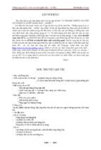
Figure 1 Instrumentations and
measurements, (a) dial
gauges, (b) actual slippage
The second set of test consists only of AFRP bars. The AFRP bars used in this set have the
same properties as the bars used for the initial testing. For this test the bond slip model was
observed. In order to accurately capture the model, dial gauges were implemented on the testing
equipment. The test consists of 4 different groups similar to that of the previous test with the
water to cement ratio varying from 0.32 to 0.44. After the concrete is placed in the wooden
formwork, it is left to harden for a full 24 hours. After this, it is placed in a waterbed to cure for
an additional 6 days. This makes a full week after the concrete is mixed and poured in which it
will be put under a compression and pullout test. Once the concrete was cured, compression test
and pullout test were conducted using the UTM (universal testing machine) in the lab. In order to
perform the pullout test, an apparatus was designed to contain the cubed specimens. Two steel
plates and four steel rods were crafted together using steel bolts and nuts to create the apparatus.
The second set consists of investigating the bond-slip relationship between the AFRP bars
and the SCC. Two dial gauges were used to test the slippage of the AFRP bars. The first dial
gauge was fixed to the AFRP bar to obtain relative slip reading between the bar and apparatus.
The second dial gauges were fixed to the UTM to indirectly verify the slip measurement of the
AFRP bars in the concrete. Factors such as slippage of the bar in the top grip, movement of the
dial gauge on the bar and bar shredding were taken into account when preparing for this test
(Figure 1). The actual slippage was obtained by using measuring equipment in order to validate
reading of dial gauges. After the test was conducted, the specimens were carefully split open to
measure the length of the void left once the bar was pulled out. This data was used to calibrate
the reading of the dial gauges and determine a modification factor to adjust the time-slip reading.
5. Results
Compression test were performed on the different groups of concrete. With these tests, a
relationship was created to understand how the dosage of superplasticizer effects on the
compression strength of the SCC. The cylinder specimen tested had a size of 100 mm radius and
© ASCE
6
a height of 200 mm. From Group 1 with no dosage of superplasticizer, there is a 56% increase in
bond strength to Group 2, which contains 5 oz. per 100 lbs. per cement. From Group 2 to Group
3, there is an 8% increase in compression strength. From this point, there is a 6.3% increase in
compression strength to Group 4. From Group 4 there is an increase of 4.8% in compression
strength from this point to Group 5. There is an overall increase of 88% in compression strength
from Group 1, which contains no dosage of superplasticizer, to Group 5, which contains 8 oz. per
100 lbs. of cement.
Table 4 Results of compression test (cylinder 100mm diameter and 200mm height) and
slump flow
Group No.
Specimen No.
Group 1
Group 2
Group 3
Group 4
Group 5
SSC-G1(1-3)
SSC-G2(1-3)
SSC-G3(1-3)
SSC-G4(1-3)
SSC-G5(1-3)
Dosage of SP (oz. per
100 Lbs. Of Cement)
0
5
6
7
8
Average Compression
Strength (MPa)
20.10
31.42
33.96
36.13
37.87
Slump Flow
Inches (mm)
N/A
13 (330.2)
16 (406.2)
21.5 (546.1)
25.5 (647.7)
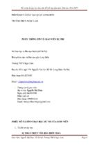
This data can be observed in Table 4. The data was displayed in Figure 2.a, to show the increase
of compression strength with the increase of superplasticizer dosage. The slump flow was taken
for each group of concrete. The data shows there is an increase in slump flow with addition of
superplasticizer. There is an increase of 96% in slump flow from a superplasticizer dosage of 0
oz. per 100 lbs. of cement which has a slump flow of 13 inches to a slump flow of 25.5 inches
which has dosage of 8 oz. per 100 lbs. of cement. This is due to the increase of followability that
occurs when superplasticizer dosage is increased. This can be seen in the Figure 2b
Pullout tests were performed for each group of concrete to see how the dosage of
superplasticizer effects the bond behavior between the AFRP bars and SCC. Using the steel
apparatus constructed, the pullout test was conducted. With this data, the relationship between
the bond strength and dosage of superplasticizer will be determined. This data can be seen in
Table 5. From the result shown, there is a polynomial relationship between the bond strength and
40
27
a
35
b
24
30
25
Group 1
Group 2
Group 3
Group 4
Group 5
20
15
Slump flow (inch)
Compression Strength (MPa)
Downloaded from ascelibrary.org by RMIT UNIVERSITY LIBRARY on 01/05/19. Copyright ASCE. For personal use only; all rights reserved.
Structures Congress 2017
21
18
15
12
0
2
4
6
8
Dosage of superplasticizer (Oz. per 100 lbs of cement)
4
5
6
7
8
Dosage of superplasticizer (Oz. per 100 lbs of cement)
Figure 2 Effect of superplasticizer on compression strength and slump
flow, (a) compression strength of concrete as a function of
superplasticizer dosage, (b) influence of superplasticizer on slump
flow
© ASCE
9
Downloaded from ascelibrary.org by RMIT UNIVERSITY LIBRARY on 01/05/19. Copyright ASCE. For personal use only; all rights reserved.
Structures Congress 2017
7
superplasticizer dosage. The result from the compression strength showed that there is a positive
linear relationship between the compression strength and the dosage of superplasticizer. The
relationship between the compression strength and the bond strength can now be determined.
From the data, there is slight increase of 16% in bond strength from Group 1 (no dosage of
superplasticizer) to Group 2 (5 oz. of 100lb of cement). From Group 2 to Group 3 there is drastic
decrease in bond strength. The data shows there is a 25 % decrease in bond strength. From
Group 3 to Group 4 the curve continues to decline with a decrease of 22 % in bond strength.
From this point, there is a slight increase in bond strength from Group 4 to Group 5 of 10%.
Overall, there showed to be a 16% increase from Group 1 to Group 2 and then a 36% decline in
bond strength from Group 2 to Group 5. This data can be seen in Figure 3a.
Table 5 Average results of the pullout test in the Set I
Group
No.
Test
No.
G1
G2
G3
G4
G5
G1-S
G2-S
G5-S
1-3
4-6
7-9
10-12
13-15
16-18
19-21
22-24
Dosage of SP
(ounces. per 100
lbs. Of Cement)
0
5
6
7
8
0
5
8
Bar
type
AFRP
AFRP
AFRP
AFRP
AFRP
Steel
Steel
Steel
Diameter
Inches
(mm)
0.5 (12.7)
0.5 (12.7)
0.5 (12.7)
0.5 (12.7)
0.5 (12.7)
0.56 (14.3)
0.56 (14.3)
0.56 (14.3)
Peak
Load
(lbf)
6454
7527
5610
4336
4796
12085
12030
12804
Bond
Strength
(MPa)
7.08
8.26
6.16
4.76
5.26
11.79
11.73
12.49
The steel bars that were tested had bar diameters and embedment length similar to that of
the AFRP bars. This phase in the testing consist of three groups of concrete from the first set of
test (Group 1, 2 and Group 5). The bond strength for these bars stayed relatively close ranging
from 11.78 MPa to 12.48 MPa. The trend line stayed primarily flat from Group 1 to Group 5.
The data can be seen in the Figure 3b. The superplasticizer has shown to have a greater effect on
the bond strength of the AFRP bars and SCC than the steel rebar. This is due to the physical
interaction of the steel rebar and the SCC due to its physical characteristics. In Figure 3b, it
shows that there is a small difference in the linear slope of the ACI 318.02 equation for bond
strength of steel bars and the test result of the steel bar.
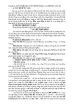
The data received from the AFRP test were compared to the ACI equation for bond
behavior of FRP bars and normal concrete. In this equation, the compression strength can be
assumed to be a factor of the change in its water cement ratio. In Figure 3a, the ACI equation is
plotted using the testing circumstances from this current testing. The data points for the ACI
equation are compared to that of the test result from the pullout test. The first group of concrete
containing zero dosage of superplasticizer, had a percentage error of 1.7% compared to the ACI
equation. The data points are very close giving the fact that at Group 1 (contains no
superplasticizer) it is normal concrete. From This point on, the difference in the data received
and the ACI equation increases. The percent error for the second group is roughly 5.6 % from the
ACI equations. From the second group to the third group, the difference in test result and
equation increases drastically. The difference in the test results and the ACI equation continues
to increase as the compression strength increases. This data shows the effects of the
superplasticizer dosage add to the concrete. This data show that the optimal dosage is obtain at a
dosage of 4 to 5oz. per 100 lbs. of cement. At this point, the concrete and bar reaches it
maximum bond strength.
© ASCE
Structures Congress 2017
8
20
AFRP
Steel
ACI 318.02
16
SP=0
6
SP=6
SP=8
12
10
8
6
4
5
2
SP=7
SP=6
7
14
SP=5
SP=5
SP=0
8
Bond strength (MPa)
Bond Strength (MPa)
9
Downloaded from ascelibrary.org by RMIT UNIVERSITY LIBRARY on 01/05/19. Copyright ASCE. For personal use only; all rights reserved.
b
18
SP=8
a
Test results
ACI 440.1R-06
SP=7
10
0
4
18
21
24
27
30
33
36
Compression Strength (MPa)
39
42
18
20
22
24
26
28
30
32
34
36
38
40
Compression strength (MPa)
Figure 3 Evaluation of bond strength for AFRP and steel bars of present test, (a)
Comparing bond strength of AFRP bars and ACI 440.1R-06, (b) Bond strength of AFRP,
steel deformed bars, and ACI 318.02 equation (Anon., 2002)
6. Bond-Slip Model
The dial gauges that were used had a maximum reading of 13.63 mm. For the bars that had a
final slip greater than 13.63 mm, a modification factor was determined by comparing the data
received from the dial gauges and the displacement giving from the UTM. With this
information, the slip after 13.63 mm can accurately be accounted for. After this, the final slip is
compared to the measurement of the actual slippage. The data received showed that reading from
dial gauges were very close to the measurements of the actual slippage. The overall average
shows that the data from the dial gauges were within 2% percent of the actual slippage
measurement. In order to properly measure the bond slip model, dial gauges were used to
measure the slippage of the AFRP bars. Once the data from the dial gauges and the UTM is
received, the time interval was set equivalent in order to match the bond stress with the slippage
at a specific time. Figure 4 shows that the bond slip relationship for the AFRP bars and for each
group of SCC. The four groups differed in its water to cement ratio.
The average bond-slip model for each group can be seen in Figure 4. This figure displays
the ascending branch of each group. From this data gathered, the water cement ratio shows to
have no real effects on the slope of the bond slip curve for the AFRP bars and the SCC. The
slope at the earlier stages of the bond slip model for AFRP bars showed not to be as steep as that
of steel. The data obtained shows that with decreasing the water to cement ratio, the slip at
maximum bond stress increases. From Group 6 (0.44 w/c ratio) the slip at the maximum bond
stress is at 4.61 mm. To Group 7 (0.4 w/c ratio), the slip increases by 44% to 6.64 mm. From this
point to Group 8 (0.36 w/c ratio), there is an increase of 25% in slip. From Group 8 to Group 9
(0.32 w/c cement ratio) the slip increased by another 9.6 %.
© ASCE
Structures Congress 2017
9
Group 1
5.5
Group 2
Average of Group1
Average of Group 2
5
Bond Stress (MPa)
Bond Stress (MPa)
4.5
4.0
3.5
3.0
2.5
2.0
4
3
2
1
1.5
1.0
0
0
1
2
3
4
5
-1
0
1
2
4
5
6
7
Group 4
Group 3
4.5
3
Slippage (mm)
Slippage (mm)
Average of Group 3
Average of Group 4
5
4.0
Bond Stress (MPa)
3.5
Bond stress (MPa)
Downloaded from ascelibrary.org by RMIT UNIVERSITY LIBRARY on 01/05/19. Copyright ASCE. For personal use only; all rights reserved.
5.0
3.0
2.5
2.0
4
3
2
1.5
1
1.0
0
0.5
0
2
4
6
Slippage (mm)
8
10
0
2
4
6
8
10
Slippage (mm)
Figure 4 Average Bond-Slip for each group of SCC
7. Conclusions
This paper shows how the dosage of superplasticizer plays a factor into the bond behavior of the
AFRP bar and the SCC. The effects of the amount of superplasticizer on the compression
strength was investigated as well. The bond slip model of the AFRP bars with varying water
cement ratio is displayed.
The optimal bond strength for the AFRP bar and SCC can be attained at a dosage of 4
and 5 ounces of superplasticizer per100 lbs. of cement. From this point, there is a
decrease of 42.3% in bond strength from a dosage of 5 to 7 ounces per 100 lbs. cement
(Group 2 to Group 4). This shows that the superplasticizer dosage has a great influence
on the bond behavior.
The decrease in water cement ratio showed to have an opposite effect on the slip at the
maximum bond stress. As the water cement ratios decreases from 0.44 to 0.32, the slip at
maximum bond increases 98% in slip from a slippage of 4.61 mm to a slippage of 9.15
mm.
The compression test showed that increasing the dosage of superplasticizer has a positive
effect on the compression strength. When increasing the superplasticizer dosage to 8
ounces per 100 lbs., the compression strength increased by 88% compared to normalweight concrete (0 oz. per 100 lb. cement)
© ASCE
Structures Congress 2017
Downloaded from ascelibrary.org by RMIT UNIVERSITY LIBRARY on 01/05/19. Copyright ASCE. For personal use only; all rights reserved.
References
Anon., 1994. AS 3600, North Sydney, Australia: Australian Standard for Concrete Structures.
Anon., 2002. ACI 318-02, Building Code Requirements for Structural Concrete, s.l.: s.n.
Anon., 2003. ACI 408 R-03, Bond and Development of Straight Reinforcing Bars in Tension, s.l.:
ACI Commitee.
Anon., 2004. ACI 440, Guide Test Methods for Fiber-Reinforced Polymers (FRPs) for
Reinforcing or Strengthening Concrete Structures, s.l.: ACI Committee.
Anon., 2006. ACI 440.1R-06, Guide for the design and construction of concrete reinforced with
FRP bars, Farmington Hills, Mich: American Concrete Institute (ACI).
Brettmann, B. B., Darwin, D. & Donahey, R. C., 1986. Bond of Reinforcement to
Superplasticized Concrete. Journal Proceedings, 83(1), pp. 98-107.
Cosenza, E., Manfredi, G. & Realfonzo, R., 1997. Behavior and Modeling of Bond of FRP
Rebars to Concrete. Journal of Composite for Construction, pp. 40-51.
Esfahani, M. & Rangan, B., 1998. Local bond strength of reinforcing bars in normal strength and
high strength concrete (HSC). ACI Structural Journal, 95(2), p. 96–106.
Esfahani, M. R. & Rangan, V., 1998. Bond between normal strength and high-strength concrete
(HSC) and reinforcing bars in splices in beams. ACI Structural Journal, Volume 95-3, pp.
272-280.
Ghafoori, N., Najimi, M. & Aqel, M. A., (2014. Abrasion Resistance of Self-Consolidating
Concrete. Journal Of Materials In Civil Engineering, pp. 296-303.
Gibb, A., Glass, J., Goodier, C. & Rich, D., 2012. UK Contractors’ Views on Self-Compacting
Concrete in Construction. ICE Publishing, Issue , pp. pp. 1-9.
Golafshani, E. M., Rahai, A. & Sebt, M. H., 2014. Bond behavior of steel and GFRP bars in selfcompacting concrete. Construction and Building Materials, Volume 61, p. 230–240.
Kassimi, F., El-Sayed, A. K. & Khayat, K. H., 2014. Performance of Fiber-Reinforced SelfConsolidating Concrete for Repair of Reinforced Concrete Beams. ACI Structural Journal,
Volume 111-S108, pp. 1277-1286.
Kocaoz, S., Samaranayake, V. & Nanni, A., 2015. Tensile Characterization of Glass FRP Bars.
Composites, 24 Sept, 36(2), p. 127–134.
Lee, Y. H., Kim, M. S., Kim, H. L. J. & Kim, D., 2013. Experimental study on bond strength of
fiber reinforced polymer rebars in normal strength concrete. Journal of adhesion science and
technology, 27(5-6), pp. 508-522.
Lin, X. & Zhang, Y., 2013. Evaluation of bond stress-slip models for FRP reinforcing bars in
concrete. Composite Structures, pp. 131-141.
Melo, J., Rossetto, T. & Varum, H., 2015. Experimental study of bond–slip in RC structural
elements the bond strength with plain bars. Materials and Structures, pp. 2367-2381.
Okelo, R. & Yuan, R. L., 2005. Bond Strength of Fiber Reinforced Polymer Rebars in Normal
Strength Concrete. Journal Of Composites For Construction, Volume 9.3, pp. 203-213.
Orangun, C. O., Jirsa, J. O. & Breen, J. E., 1977. A Reevaluation of Test Data on Development
Length and Splices. ACI Journal, pp. 114-122.
Shen, D. et al., 2016. Experimental study of early-age bond behavior between high strength
concrete and steel bars using a pull-out test. Construction and Building Materials, pp. 653663.
Tastani, S. P., Pantazopoulou, S. J. & Karvounis, P., 2005. Local Bond - Slip Characteristics of
G-FRP Bars. Conference Paper, pp. 1-17.
© ASCE
10
Structures Congress 2017
Downloaded from ascelibrary.org by RMIT UNIVERSITY LIBRARY on 01/05/19. Copyright ASCE. For personal use only; all rights reserved.
Xing, G., Zhou, C., Wu, T. & Liu, B., 2015. Experimental Study on Bond Behavior between
Plain Reinforcing Bars and Concrete. Advances in Materials Science and Engineering, pp. 19.
Zia, P., Nunez, R. A. & Mata, L. A., 2005. Implementation of self-consolidating concrete for
prestressed concrete girders, Raleigh: Federal Highway Administration, The United States
Department of Transportation.
© ASCE
11
Structures Congress 2017
12
Dolores River Bridge—Bedrock, CO: Remote Site Solution for Deep Scour
Jonathan E. Emenheiser1 and Gregory S. Lingor2
1
Downloaded from ascelibrary.org by RMIT UNIVERSITY LIBRARY on 01/05/19. Copyright ASCE. For personal use only; all rights reserved.
CH2M, Transportation Business Group, 9191 South Jamaica St., Englewood, CO
80112. E-mail:
[email protected]
2
CH2M, Transportation Business Group, 9191 South Jamaica St., Englewood, CO
80112. E-mail:
[email protected]
Abstract
The Dolores River Bridge in Bedrock, Colorado carries SH-90 over the Dolores
River. The bridge is in a remote location and crosses a channel that has the potential
for deep scour during the extreme flooding event. The structure was designed with a
combined focus on cost, constructability, and hydraulic performance during both the
design and extreme events.
The superstructure consists of concrete bulb tee girders and precast deck panels and
the substructure consists of steel H-piles with precast concrete abutment caps. All
bridge components except the barrier curb were designed using precast concrete
elements because the site location is far from ready-mix concrete plants. The precast
elements were designed and detailed to connect using high strength threaded rods and
tolerances were established to allow for field adjustment and avoid lengthy delays
during construction.
The 100-year flood event has the potential to lower the channel grade by nearly 17
feet. To mitigate this, the abutment walls and wing walls were designed using driven
sheet piles with rip rap protection. For the 500-year extreme event, the abutment was
designed to remain stable and allow the roadway embankment to be replaced,
providing a much faster and more economical repair than a complete structural
replacement.
This paper presents the unique design challenges of this structure and the solutions
that were developed and implemented to meet the challenges while providing a cost
effective product.
This paper will provide an understanding of bridge abutment design that combines
deep foundations for structural stability during the extreme scour event and sheet pile
wing walls for stability during the intermediate scour event. The paper will also
provide an understanding of the design and detailing considerations for a bridge
structure using entirely precast components.
© ASCE