Downloaded from ascelibrary.org by RMIT UNIVERSITY LIBRARY on 01/05/19. Copyright ASCE. For personal use only; all rights reserved.
Structures Congress 2017
Blast, Impact Loading, and
Response of Structures
Selected Papers from the
Structures Congress 2017
Denver, Colorado
April 6–8, 2017
Edited by
J. G. (Greg) Soules, P.E., S.E., P.Eng
Downloaded from ascelibrary.org by RMIT UNIVERSITY LIBRARY on 01/05/19. Copyright ASCE. For personal use only; all rights reserved.
Struc
S cturres Cong
C gresss 20017
Blast, Impac
I
ct Loa
adingg, andd Respponsee
of Strructures
SELECTE
ED PAPER
RS FROM THE
T
STRUC
CTURES C
CONGRESS
S 2017
Apriil 6–8, 201 7
Denver, Coloraddo
SPON
NSORED BY
Y
The Strructural En
ngineering Institute (S
SEI)
of the American
A
Society of C
Civil Enginneers
ED
DITED BY
J. G. (Greg) Soules, P.E., S.E., P.Enng
Published
P
by
b the Amerrican Societyy of Civil En
ngineers
Downloaded from ascelibrary.org by RMIT UNIVERSITY LIBRARY on 01/05/19. Copyright ASCE. For personal use only; all rights reserved.
Published by American Society of Civil Engineers
1801 Alexander Bell Drive
Reston, Virginia, 20191-4382
www.asce.org/publications | ascelibrary.org
Any statements expressed in these materials are those of the individual authors and do not
necessarily represent the views of ASCE, which takes no responsibility for any statement
made herein. No reference made in this publication to any specific method, product, process,
or service constitutes or implies an endorsement, recommendation, or warranty thereof by
ASCE. The materials are for general information only and do not represent a standard of
ASCE, nor are they intended as a reference in purchase specifications, contracts, regulations,
statutes, or any other legal document. ASCE makes no representation or warranty of any
kind, whether express or implied, concerning the accuracy, completeness, suitability, or
utility of any information, apparatus, product, or process discussed in this publication, and
assumes no liability therefor. The information contained in these materials should not be used
without first securing competent advice with respect to its suitability for any general or
specific application. Anyone utilizing such information assumes all liability arising from such
use, including but not limited to infringement of any patent or patents.
ASCE and American Society of Civil Engineers—Registered in U.S. Patent and Trademark
Office.
Photocopies and permissions. Permission to photocopy or reproduce material from ASCE
publications can be requested by sending an e-mail to
[email protected] or by locating a
title in ASCE's Civil Engineering Database (http://cedb.asce.org) or ASCE Library
(http://ascelibrary.org) and using the “Permissions” link.
Errata: Errata, if any, can be found at https://doi.org/10.1061/9780784480397
Copyright © 2017 by the American Society of Civil Engineers.
All Rights Reserved.
ISBN 978-0-7844-8039-7 (PDF)
Manufactured in the United States of America.
Structures Congress 2017
iii
Prreface
Downloaded from ascelibrary.org by RMIT UNIVERSITY LIBRARY on 01/05/19. Copyright ASCE. For personal use only; all rights reserved.
The Structures Congress
C
hass a robust tecchnical proggram focusinng on topics important too
Strucctural Engin
neers.
The papers in the proceeding
g are organizzed in 4 voluumes
ume 1 includ
des papers on
n Blast and Impact
I
Loadding and Ressponse of Strructures
Volu
Volu
ume 2 includ
des papers on
n Bridges an
nd Transporttation Structuures
Volu
ume 3 includ
des papers on
n Buildings and Nonbuillding and Sppecial Structtures
Volu
ume 4 includ
des papers on
o Other Strructural Enggineering Toppics includinng; Business
and Professional Practice, Natural
N
Disaasters, Nonsttructural Syystems and C
Componentss,
orensics
Educcation, Research, and Fo
Acknow
A
wledgm
ments
Prep
paration for the Structurres Congress required ssignificant tiime and efffort from thee
mem
mbers of th
he National Technicall Program Committeee, the Loccal Planningg
Com
mmittee. Mucch of the succcess of the conference
c
rreflects the ddedication annd hard workk
by th
hese volunteeers.
We would
w
like to thank GEIICO and Peaarl for Sponssoring the Congress procceedings andd
supp
porting the Structures Co
ongress in su
uch a generouus way.
The Joint Progrram Committtee would like
l
to acknnowledge thee critical suupport of thee
spon
nsors, exhibiitors, presen
nters, and mo
oderators whho contributted to the suuccess of thee
confference throu
ugh their parrticipation.
o dedicated volunteerrs and staff,
f, we wouldd like to thank you for
On behalf of our
nding your valuable
v
timee attending the
t Structurees Congresss. It is our hhope that youu
spen
and your
y
colleag
gues will ben
nefit greatly from the infformation prrovided, learrn things youu
can implement
i
and
a make pro
ofessional co
onnections thhat last for yyears.
Sinccerely,
J. Grreg Soules, P.E.,
P
S.E., P..Eng, SECB, F.SEI, F.A
ASCE
© ASCE
Structures Congress 2017
iv
Contents
Downloaded from ascelibrary.org by RMIT UNIVERSITY LIBRARY on 01/05/19. Copyright ASCE. For personal use only; all rights reserved.
Blast and Impact Loading and Response of Structures
Performance of Girder Bridges under the Composite Action of Blast
Loads and Earthquakes ............................................................................................. 1
Jingyu Wang, Wancheng Yuan, and Fengming Wang
Blast Response of 60 MPa Reinforced Concrete Slabs Subjected to
Non-Confined Plastic Explosives ............................................................................. 15
Fausto B. Mendonca, Girum S. Urgessa, and José A. F. F. Rocco
Calibration of Barge Models for the Reliable Prediction of Impact Force on
Bridge Piers ............................................................................................................... 27
D. S. Saini and B. Shafei
Experimental and Analytical Alternate Load Path Analysis for Reinforced
Concrete Flat Plates .................................................................................................. 37
Ahmed Khalil and Sarah Orton
New Methodology for Designing ATFP Using the Modified Alternate Load
Path Method .............................................................................................................. 51
Ayman Elfouly, Ahmed Khalil, and Nabil A. Rahman
Effects of Blast-Induced Permanent Deflections on the Performance of
Load-Bearing Steel Elements in Fire ...................................................................... 66
L. Magenes, T. J. Mander, and M. A. Morovat
Experimental and Numerical Analysis for Non-Load Bearing Sandwich
Wall Panels for Blast Mitigation ............................................................................. 77
A. E. El-Sisi, A. Saucier, H. A. Salim, and M. Nawar
Progressive Collapse Performance of Buildings and the Contribution of
Infill Walls ................................................................................................................. 86
Kai Li, Curtis Wood, and Halil Sezen
Dynamic Response of Reinforced Concrete Bridge Piers Subjected to
Combined Axial and Blast Loading ........................................................................ 98
Olaniyi Arowojolu, Muhammad Kalimur Rahman, and
Baluch Muhammad Hussain
© ASCE
Structures Congress 2017
Explosive Test Chamber: Analysis and Design.................................................... 110
Yousef Alostaz and Asher Gehl
Downloaded from ascelibrary.org by RMIT UNIVERSITY LIBRARY on 01/05/19. Copyright ASCE. For personal use only; all rights reserved.
Nonlinear Dynamic Analysis on the Progressive Collapse Response of an
RC Frame with Perforated Infill Walls ................................................................ 119
Sidi Shan, Shuang Li, Changhai Zhai, and Lili Xie
Deflagration Load Generator Blast Load Testing of an ISO Shipping
Container and Blast Resistant Wood Building .................................................... 130
T. H. Anderson, B. J. Horn, J. K. Thomas, and L. Magenes
Modeling and Testing of Shear Connections with Beams under Tension
Membrane Loading ................................................................................................ 153
David Holgado, Robert Driver, and Darrell Barker
Is the Load Transfer Mechanism of Each Story in a Multi-Story Building
the Same Subjected to Progressive Collapse? ...................................................... 165
Jun Yu and Ji-wei Tian
The Effects of Bracing on the Behavior of RC Multi-Story Frames to Resist
Progressive Collapse ............................................................................................... 180
Kai Qian, Yang Yu, Yue-Ming Wang, and Bing Li
Performance of Precast Concrete Planks Subjected to Hail Impact
Loads—A Case Study ............................................................................................. 187
Dziugas Reneckis, Vicki Lam, and Remo Capolino
Development of Blast Response Limits for Load-Bearing Prestressed
Concrete Panels Using Full-Scale Shock Tube Test Data ................................... 197
Thomas J. Mander, Michael J. Lowak, and Michael A. Polcyn
The Current State of Automated Building Design and Fast-Running
Analysis for Vulnerability Studies ........................................................................ 209
S. A. Minkoff, J. F. Nichols, and G. Doyle
Acceptance Criteria for the Nonlinear Alternative Load Path Analysis of
Steel and Reinforced Concrete Frame Structures ............................................... 222
J. M. Weigand, Y. Bao, and J. A. Main
Alternative Load Path Analysis of a Prototype Reinforced Concrete
Frame Building ....................................................................................................... 233
Yihai Bao, Joseph A. Main, and H. S. Lew
An Overview of Missile Impact Tests on Steel-Plate Composite (SC)
Walls......................................................................................................................... 245
Joo Min Kim, Jakob Bruhl, Jungil Seo, and Amit Varma
© ASCE
v
Structures Congress 2017
vi
Preliminary Investigation of Local Failure Modes in Steel-Plate
Composite Walls Subjected to Missile Impact ..................................................... 256
Joo Min Kim, Jakob Bruhl, Jungil Seo, and Amit Varma
Forensics
Downloaded from ascelibrary.org by RMIT UNIVERSITY LIBRARY on 01/05/19. Copyright ASCE. For personal use only; all rights reserved.
Lovettsville Water Tank Column Rupture Forensic Investigation ................... 262
Donnell Duncan
Investigation into the Failure of a Long-Span Glued Laminated Beam............ 276
A. M. Shuck, J. A. Porto, and K. K. Sasaki
Structural Building Condition Reviews: Beyond Distress .................................. 289
James A. D’Aloisio
Observations of Snow Load Effects on Four School Buildings in
New England ........................................................................................................... 302
R. A. Daniel Bass and Michael O’Rourke
Determining the Effects of Construction Quality, Age, and Deterioration
on the Resistance to Loads ..................................................................................... 314
William L. Coulbourne
© ASCE
Structures Congress 2017
1
Performance of Girder Bridges under the Composite Action of Blast Loads
and Earthquakes
Jingyu Wang1; Wancheng Yuan2; and Fengming Wang3
1
Downloaded from ascelibrary.org by RMIT UNIVERSITY LIBRARY on 01/05/19. Copyright ASCE. For personal use only; all rights reserved.
State Key Laboratory of Disaster Reduction in Civil Engineering, Tongji Univ.,
No.1239
Siping
Rd.,
Yangpu
District,
Shanghai
200092.
E-mail:
[email protected]
2
State Key Laboratory of Disaster Reduction in Civil Engineering, Tongji Univ.,
No.1239 Siping Rd., Yangpu District, Shanghai 200092. E-mail:
[email protected]
3
Shandong Provincial Communications Planning and Design Institute, No.576 West
Wuying Mountain Rd., Tianqiao District, Jinan City 250000. E-mail:
[email protected]
Abstract
The research focuses on the dynamic performance of girder bridges and the
applicability of cable-sliding friction bearing subjected to blast load and earthquake. In
order to accomplish this, numerical simulation and scale model test are performed. In
numerical simulation, two seismic waves combing with blast load of 450kg TNT are
applied to the girder bridge separately by using software LS-DYNA. After analyzing the
area of damage and longitudinal displacement, results show that the most remarkable
displacement change of main girder appears when blast occurs at the time that seismic
response arrives at the maximum value. Based on the existing research, cable-sliding
friction bearing is suggested to be adapted. Next, scale model test is conducted
considering two different damping bearing systems and three series of tests are
performed to verify the effectiveness of the cable-sliding friction bearing system. The
data collected from the test shows that the bearing could prevent beam falling and
therefore improve the safety of girder bridges.
Keywords: Girder bridges; Composite action; Blast load; Earthquake; Numerical
simulation; Scale model test; Cable-sliding friction bearing.
INTRODUCTION
Recently, the transportation of dangerous goods is increasing, which lead to frequent
vehicle explosion accidents. Besides, terrorist blast attacks happen frequently in the
word. All these factors make blast load become a potential threat to the safety of bridge
structures. However, blast effect has not been considered in design and construction
standards for bridges in China until now. Specific construction requirements for
anti-explosion properties of bridges have not been put forward. The report No.645 of
National Cooperative Highway Research Projects “Blast-resistant Highway Bridges:
Design and Detailing Guidelines” is the relatively authoritative literature among current
© ASCE
Structures Congress 2017
Downloaded from ascelibrary.org by RMIT UNIVERSITY LIBRARY on 01/05/19. Copyright ASCE. For personal use only; all rights reserved.
anti-explosion research (Williamson 2010). But only simple guidance is provided in this
reference, and comprehensive information about failure modes for components of
bridges are failed to provide (Yi et al. 2013). On the contrary, the concept of seismic
design for bridges becomes prominent in recent years and corresponding methods are
relatively mature as many specifications have been amended or completed. Thus,
whether bridges that are based on seismic resistance have the ability to withstand the
impact of blast load needs to be further researched. In addition, when an earthquake
occurs, it’s highly possible that trucks loaded with dangerous goods will explode due to
crashes. Widespread damage is likely to happen under the composite action of blast load
and earthquake. Thus, the design of bridges under multiple extreme loads especially
blast load and earthquake has become the forefront of current research.
From 2003, the group of Pr. George C. Lee for the disaster research center of the state
university at Buffalo has conducted the research on design of bridges subjected to
multiple hazards based on probability with the support from federal highway in US. The
concept for design of load and resistant coefficient under multiple hazards was put
forward and a variety of loading combinations were taken into consideration (George et
al. 2011). The frame of steel-tube-concrete piers was regarded as the research object by
Fujikura, and performance of piers were observed under the effect of blast and
earthquake respectively (Fujikura et al. 2008). An effective method for calculating the
load combination coefficient was put forward and analyzed considering the combination
of earthquake and heavy trucks as the research object (Sun Dezhang and Sun Baitao
2012; Sun Dezhang 2013). In the research, the steel-tube-concrete and
steel-protecting-tube piers which are applicable to aseismic design were analyzed. And
result showed that the anti-explosion performance has been improved significantly
compared with the ordinary concrete piers (Fouche et al. 2013; Kyei et al. 2014).
To sum up, the explosion-proof research of bridges is still in its infancy at present.
Combination effect of blast load and earthquake subjected to bridges has not been
involved basically. To bridge the gap, the focal point of this paper is to investigate the
dynamic performance of girder bridges and applicability of cable-sliding friction bearing
under composite action of blast load and earthquake. Various methods including
numerical simulation and experimental test are involved in the test. As for numerical
simulation, two different seismic waves combing with blast load of specific magnitude
(450kg TNT) are applied to specific girder bridge respectively. The time when explosion
happens is settled to distribute evenly after the time that the largest seismic response of
bridge occurs.
Based on the research of numerical simulation, cable-sliding friction bearing is
suggested to be adapted which could limit the large relative displacement between main
girders and piers caused by earthquake and blast load. Further, scale model test is
conducted considering two different damping bearing systems including cable-sliding
friction bearing system and non-cable friction bearing system. Three series of tests are
© ASCE
2
Structures Congress 2017
3
perfo
ormed in th
he research including blast
b
loadingg test, earthhquake loadding test and
comp
posite test of the two ex
xtreme loadss. The dynam
mic characteer of the moodel bridge iis
observed and ap
pplicability of
o the cablee-sliding fricction bearinng under varrious loadingg
cond
ditions could
d be evaluated.
Downloaded from ascelibrary.org by RMIT UNIVERSITY LIBRARY on 01/05/19. Copyright ASCE. For personal use only; all rights reserved.
RES
SPONSE AN
NALYSIS OF
O GIRDER
R BRIDGE U
UNDER CO
OMPOSITE
E ACTION
OF BLAST
B
LOA
AD AND EA
ARTHQUA
AKE
Th
he purpose of
o the analyssis is to expllore the reacction and dam
mage condittion of girdeer
bridg
ges under composite
c
action
a
of blast load aand earthquaake. Two vvariables arre
invesstigated in this researcch: damage area and longitudinall displacem
ment. Generaal
nonliinear dynam
mic analyzin
ng software LS-DYNA is used in tthe simulatioon, and blasst
load is conducted
d by using th
he computerr system ConnWep.
In
n the study, a 30m span girder
g
bridgee is regardedd as the prottotype of whhich the crosss
section for main girder is com
mposed of fiive pieces off boxes. Thee concrete is simulated byy
g Solid164 in
i the finite element mod
del (Yang Yu
Yuqi et al. 2012; Wu Jiannqiang 2006)).
using
Elasttic material is used to simulate the capping beaam without considering the damagee.
BEA
AM161 is ad
dopted to siimulate the reinforcemeent, stirrup and pre-streessed ribbonn.
Rein
nforcement and
a concretee are modelled and divvided separrately, and tthen coupled
togetther. Laminaated rubber bearing is substituted by using coontact (Zhanng Tao et all.
2013
3). For the in
nsignificant interaction between
b
maiin girders annd piers undder blast loadd,
main
n girder is caalculated ind
dividually wiithout considdering the efffect of barrier in order to
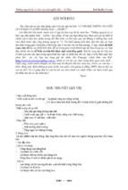
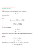
imprrove the calcculation efficciency (see Figure
F
1).
Figure 1.
1 The model of
o main girderr and reinforccement
Th
he explosion
n center is fixed at girderr No.3 with 1.2m heightt from the deeck verticallyy
and the amountt of 450kg TNT is co
onsidered inn the subseequent anallysis withouut
considering the collapse off the main girder (Liu Chao 20122). Two seismic wavessTriniidad and EL
L Centro of which the response
r
vallue for displlacement is different arre
seleccted as the earthquake load. Wheth
her the respponse of strructure undeer compositte
actio
on is influen
nced by thee displacemeent of seism
mic wave coould be invvestigated byy
comp
parative analysis. The peeak acceleraation of bothh seismic wavves is adjustted to 0.6g inn
orderr to make th
he seismic response
r
of bridges moore apparentt. For Triniddad, the tim
me
when
n the blast lo
oad happenss is settled to be at threee different ttime spots inncluding 10ss,
© ASCE
Structures Congress 2017
4
Downloaded from ascelibrary.org by RMIT UNIVERSITY LIBRARY on 01/05/19. Copyright ASCE. For personal use only; all rights reserved.
15s and
a 20s in th
he condition for composiite action. Besides, for E
EL Centro, thhe time whenn
the blast
b
load haappens is setttled to be at four time sspots includding 5s, 15s, 25s and 355s
for composite acction.
Th
he damage condition
c
off main girdeer under com
mposite actioon of Triniddad and blasst
load or EL Centtro and blasst load are listed in Tabble 1. For thhe longitudinnal action oof
hquake, no coupling
c
efffect appears while the vvertical imppact of mainn beam takees
earth
placee. So, the damage
d
areaa does not expand.
e
Butt little increease appearss in terms oof
longiitudinal leng
gth for EL Ceentro compaaring with Trrinidad.
Tablee 1. The damag
ge area of maiin girder undeer composite aaction of blastt load and earrthquake
ge
Damag
Trinid
dad
Areaa
Centtro
after Earthquake
E
Blaast at 15s
Blast at 20s
after
after
Earrthquake
Earthquake
Length((m)
4.6
4.8
4.6
4.6
Width(m
m)
3.5
3.5
3.5
3.5
Blast at 15s
Blaast at 25s
Blast at 35s
afterr
after
after
Earthquuake
Earrthquake
Earthquake
Damag
ge
EL
L
Blast
Blaast at 10s
Areaa
Blast
Blast
B
at 5s afteer
Earthquake
Length((m)
4.6
4.6
5.0
5.0
4.8
Width(m
m)
3.5
3.5
3.5
3.5
3.5
Laarge displacement of veertical reboun
nd for mainn girder wouuld not causee much effecct
if on
nly the blastt occurs. Ho
owever, wheen earthquakke appears aat the samee time, largeer
horizzontal displaacement of the
t infrastruccture may taake place at the instant of pop-up oof
main
n girder. It iss very likely
y that main beam
b
falls ffrom the beaaring and caause series oof
disassters. The lo
ongitudinal displacemen
d
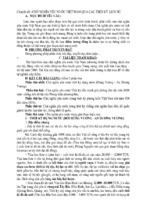
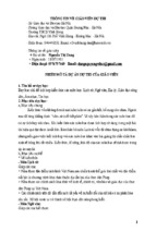
nt of main ggirder under composite action of EL
L
Centtro and blast load is sh
hown in Figu
ure 2. For bboth Trinidaad and EL C
Centro, largge
mutaation of the longitudinall displacemeent occurs att the instantt of explosioon. The mosst
remaarkable displlacement chaange of main
n girder appeears when blast occurs aat 5s after thhe
earth
hquake happens.
a) Blast at
a 5s after eartthquake happeens
© ASCE
b) Blasst at 15s after earthquake happens
Downloaded from ascelibrary.org by RMIT UNIVERSITY LIBRARY on 01/05/19. Copyright ASCE. For personal use only; all rights reserved.
Structures Congress 2017
5
c) Blast at 25s after earrthquake happ
pens
d) B
Blast at 35s affter earthquak
ke happens
Figure
F
2. The longitudinal
l
displacement
d
of
o main girderr under compoosite action (E
EL Centro)
As
A for wave Trinidad, the
t incremeent of displaacement undder compossite action iis
limitted and littlee influence is
i made to th
he main girdder. In orderr to display the variationn
moree specificallly, the long
gitudinal displacement under EL Centro andd four otheer
comp
posite loadin
ng condition
ns is shown in Table 2. The most rremarkable ddisplacemennt
chan
nge for main girder whicch is up to 12.7cm appeears when bllast occurs aat 5s after thhe
earth
hquake happ
pens. Besides, the chang
ge of displaccement for tthe rest of tthree loadingg
cond
ditions are all under control which su
uggests that tthere has a rrisk of beam falling whenn
blastt occurs at the
t time thaat seismic reesponse of m
main girder arrives at thhe maximum
m
valuee.
Tablee 2. Compariso
on of the longiitudinal displa
acement for m
main girders (E
EL Centro; Unit: cm)
Loadin
ng Condition
Only Earthquuake
Com
mposite Action
Variationn
Blast
B
at 5s after Earthquake Happens
10.0
-2.7
12.7
Bllast at 15s afterr Earthquake Happens
H
10.0
11.8
-1.8
Bllast at 25s afterr Earthquake Happens
H
10.0
14.1
-4.1
Bllast at 35s afterr Earthquake Happens
H
9.9
9.1
0.8
BLE-SLIDIN
NG FRICTIION BEAR
RING
CAB
In
n order to avoid
a
the beeam falling under compposite actionn, an effecttive isolationn
beariing known as
a the “cablee-sliding fricction bearingg” is suggessted to be addapted (Yuann
Wanccheng et al. 2010; Yuan
n Wancheng et al.2012). The bearingg, which takkes advantagge
of bo
oth the frictio
on sliding reesistance and
d the restrainnt capability of the cablees, consists oof
essen
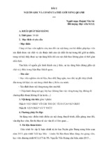
ntially a conventional po
ot bearing, high strength restrainer cables on botth sides and a
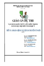
shearr bolt in the middle if neecessary (seee Figure 3).
© ASCE
Downloaded from ascelibrary.org by RMIT UNIVERSITY LIBRARY on 01/05/19. Copyright ASCE. For personal use only; all rights reserved.
Structures Congress 2017
Figurre 3. Schematiic diagram of a fixed type c able-sliding frriction bearing
Th
he performaance criteria for the cablee-sliding fricction bearingg are summaarized. Undeer
mino
or and modeerate compossite action, the
t shear boolt in a fixedd-type bearinng would noot
break
k so that no replacemen
nt of the bearring will be necessary. IIn a sliding-ttype bearingg,
the sliding
s
betw
ween the staiinless steel plate
p
and thhe Teflon pllate serves tto isolate thhe
superstructure from horizonttal ground motions
m
and ddissipate eneergy by friction while thhe
mation of thee bearing sh
hould be lesss than the ddesign free ddisplacementt.
expeected deform
Undeer a severe condition th
hat causes the
t shear boolt to breakk, the fixed--type bearingg
functtions as a sliiding-type bearing to miitigate the trransmission of earthquakke forces andd
dissip
pate energy,, while the excessive reelative displlacement bettween the suuperstructurre
and the
t pier caussed by composite action can be restraained by thee cable compponents.
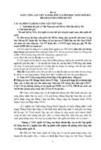
Th
he idealized hysteretic lo
oad-displaceement responnse envelopee of the bearring is shownn
in Fiigure 4, which is superp
posed by thee lateral loadd-displacemeent responsee envelope oof
slidin
ng friction bearing
b
and cables. In Figure
F
4,
denotes thhe elastic stiffness of thhe
slidin
ng friction bearing;
b
is
i defined ass the tensilee stiffness off each cablee member;
deno
otes the desig
gn free displacement wh
hen the bearinng is in norm
mal service lload.
Figurre 4. Idealized hysteretic loa
ad-displacemeent response en
nvelope of thee bearing (horrizontally)
© ASCE
6
Structures Congress 2017
7
PERFORMANCE OF GIRDER BRIDGE WITH CABLE-SLIDING FRICTION
BEARING
Design of Scale Model
Downloaded from ascelibrary.org by RMIT UNIVERSITY LIBRARY on 01/05/19. Copyright ASCE. For personal use only; all rights reserved.
Regarding a 40m span simply-supported concrete bridge as the prototype, scale
model test is carried out. Based on the existing research (Zhang Yu et al. 2016),
cable-sliding friction bearing is utilized to limit the large relative displacement between
main girders and piers caused by blast load and earthquake. The similarity relationship
between model and the prototype is attained by dimension analysis (see Table 3). In the
production process of model, organic glass is being used to simulate the fiber-reinforced
concrete, and lead is added to meet the requirements of similar weight. Based on the
principle of equivalent stiffness, the vertical and horizontal bending stiffness remain
equivalent between the prototype and model, and the influence of axial stiffness and
torsional stiffness are ignored. Model bearing is obtained from the bearing factory.
Table 3. Similarity relation between model and the prototype
Item
Material Property
Physical Quantity
Relation
Strain ε
=1
Stress σ
=
Ratio of Similitude
1
0.0699
Modulus of Elasticity E
0.0699
Poisson’s Ratio μ
Density ρ
1
/
2.237
MDC
1/80
MDC
=
Area S
=
1/6400
Displacement δ
=
1/80
=1
Rotation θ
1
Load and Internal
Force F
=
1.092e-05
Force
Bending Moment M
=
1.365e-07
Mass m
=
4.368e-06
Stiffness k
=
8.737e-4
Time t
Dynamic Character
Frequency f
=
MDC
=1
Length l
Geometric Features
Remark
.
/
= 1/
7.071e-2
DLC
14.142
DLC
Damp c
=
/
6.178e-05
Velocity v
=
/
0.177
Acceleration a
=
/
2.5
DLC
Note: “MDC” means “Model Design Control” and “DLC” means “Dynamic Loading Control”.
© ASCE
Structures Congress 2017
Simulation of Blast Load
Downloaded from ascelibrary.org by RMIT UNIVERSITY LIBRARY on 01/05/19. Copyright ASCE. For personal use only; all rights reserved.
The most important question needed to be dealt with in this test is how to simulate the
blast load. According to literature (Yang Xiumin 2010), under the impact of solid
projectile and static charge contact explosion, the reinforced concrete target boards of
different thickness have four kinds of typical failure forms including pitting, damage,
going through and cutting. Whether the projectile impact or contact explosion,
reinforced concrete plates are both under an instantaneous high-pressure pulse rendering
the similar brittle failure characters, and their failure mechanisms are the same.
Therefore, the equivalent relationship between projectile impact damage and contact
explosion damage could be used to solve the problem of contact explosion.
For a target board of certain thickness, when a projectile goes forward with a velocity
of v and the mass of m, the impulse it has is mv and the kinetic energy is m /2.
When it hits the center of target plate, its speed drops to zero, and the damage effect
made to the target board is equivalent to the damage effect made by surface contact
explosion with a certain amount of explosives . As the projectile impact and impulse
is relatively small, the energy equivalence principle could be took advantage of to get
the corresponding equivalent amount of TNT.
In the test, the whole structure is assumed to be at the linear elastic state without
considering damage. A high-elastic sphere (0.0526kg) in the state of free fall or
sinusoidal oscillation is used to simulate the blast impact. The principle of energy
conservation is applied to get the falling kinetic energy of the sphere, and this energy is
exactly the energy released from the explosion happened near the deck.
Scale Model Test
For comparative analysis, two different damping bearing systems are tested including
cable-sliding friction bearing system and non-cable friction bearing system. Three kinds
of loading conditions are conducted including blast loading test, earthquake loading test
and composite test of these two extreme loads. Six different seismic waves are selected
as incentives, testing and evaluating the applicability of the cable-sliding friction bearing
under different loading conditions. Detailed information is shown in Table 4. Shake table,
high-elastic sphere, acceleration sensors, laser displacement sensors, strain gauges and
data acquisition system are used in the test. With the help of data acquisition system, the
response of acceleration, displacement and strain from different parts of the model under
various loads are collected. After assembling and equipment calibration, the completed
test model is obtained (see Figure 5).
© ASCE
8
Downloaded from ascelibrary.org by RMIT UNIVERSITY LIBRARY on 01/05/19. Copyright ASCE. For personal use only; all rights reserved.
Structures Congress 2017
9
Figure 5. Assembled
A
testt model
Tablee 4. Loading co
ondition of the scale model test
Model
Loading Condition
C
Serial
Wave
Peaak
Load
Number
N
Form
Acceleraation(g)
T
Time(s)
E1
EL Centro
1.55
2.82
E2
CHICHI1
0.66
12.72
0.11
12.72
0.22
12.72
0.11
12.72
0.22
12.72
0.11
12.72
0.11
12.72
0.22
12.72
mpact Directionn
Im
Posittion
Disttance(cm)
B1
Above
A
the bridgge
Mid-sspan
10
B2
Along
A
the bridgge
At the End
10
B3
Cross
C
the bridgee
Mid-sspan
10
E3
Only Earthquake
(Longittudinal)
E4
E5
E6
E7
CFBS
E8
BS)
(NFB
E9
Only Blast Load
CHICHI2
CHICHI3
CHICHI4
CHICHI5
Combiination
CB1/2/3
C
E1+B1/B2/B3
Efffect
CB4/5/6
C
E3+B1/B2/B3
Note: “CFBS” mean
ns “Cable-sliding Friction Beearing System”” and “NFBS” m
means “Non-cable Friction
ng System”.
Bearin
Perfformance off the Girderr Bridge
Dynamic
D
Peerformance of
o the Girderr Bridge undder Blast Loaad
Acceleration
A
versus
v
time curve of maain girder at the mid-spaan is in dampped harmoniic
vibraation form when
w
impactt of elastic sphere
s
occuurs at the miiddle, and thhen return to
origiinal state afteer a few seconds. This phenomenon
p
n shows that the whole sstructure is inn
elastic state as beeing assumeed (see Figurre 6). The m
most dramaticc response aappears at thhe
m
girder suffers from
m the impact along the bridge at thhe
impaact location. When the main
end, the longitud
dinal accelerration of maain girder beecomes the most dramaatic, and thenn
© ASCE
Structures Congress 2017
10
Downloaded from ascelibrary.org by RMIT UNIVERSITY LIBRARY on 01/05/19. Copyright ASCE. For personal use only; all rights reserved.
the dynamic
d
resp
ponse transffers to cappiing beams aand piers thrrough bearinng. In such a
case,, the acceleraation respon
nse of cappin
ng beam is loower than m
main girder because of thhe
existting cables (ssee Figure 7(a)-(b)).
Figure
F
6. Mid-span accelera
ation versus tim
me curve of m
main girder
(a) En
nd of the main
n girder
(b) Capp
ping beam
Figure 7. Acceeleration versus time curves when impacct applied alon
ng the bridge aat the end
Under
U
the imp
pact of blastt load, the diisplacement versus time curve is witth the similaar
trend
d as acceleraation. Longittudinal and horizontal
h
blast impact m
make large ddisplacemennt
deviaation betweeen main gird
der and cappiing beam (seee Figure 8(aa)-(b)).
(a) Longitudinal
L
direction
d
(b) Horizoontal direction
n
Figurre 8. Displacem
ment versus time curve betw
ween main girrder and capp
ping beam wheen longitudinaal
and horizontal impact applied
© ASCE
Structures Congress 2017
11
Dynamic Peerformance of
o the Girderr Bridge undder Earthquaake
Downloaded from ascelibrary.org by RMIT UNIVERSITY LIBRARY on 01/05/19. Copyright ASCE. For personal use only; all rights reserved.
While
W
six diffferent seism
mic waves occcur along tthe bridge, tthe dynamicc accelerationn
respo
onse of main
n girders at the
t longitudiinal directionn is significantly lower than cappingg
beam
m in CFBS comparing
g with NFB
BS. The effficiency on reducing aand isolating
vibraation of cablle-sliding friiction bearin
ng under seissmic effects at different level is veryy
high (see Figuree 9(a)-(c)). Adding cab
bles does noot affect thee good shocck-absorptionn
perfo
ormance of the
t original bearing.
b
(a)At the bottom off piers
(b) A
At the middlee of capping beeam
(c)At the end of main ggirder
Figurre 9. Longitud
dinal accelerattion versus tim
me curve of b ridge structurres while eartthquake occurrs
along th
he bridge
Th
he maximum
m displacem
ment between
n main girdder and cappping beam iss up to 3mm
m
undeer the longitu
udinal earthq
quake, and response
r
of aall the bearinng is consisttent. Besidess,
the strain
s
of pieers at differeent height arre relativelyy small at thhe level of tthe parts peer
milliion, and retu
urn to the orriginal state after earthqquake in botth CFBS andd NFBS (see
Figure 10(a)-(b))). This indiccates that all the piers aare in elasticc range, andd the internaal
forcee of piers iss small. Mo
ost of the in
nertial forcees are cut ooff because of the cablle
beariing.
© ASCE
Downloaded from ascelibrary.org by RMIT UNIVERSITY LIBRARY on 01/05/19. Copyright ASCE. For personal use only; all rights reserved.
Structures Congress 2017
(a) Longitudiinal strain verrsus time curv
ve
of
o piers at the bottom
12
(b) Displlacement betw
ween the main girder
and cappin
ng beam
Figurre 10. Longitu
udinal displacement versu
us time curvee of bridge sttructures whiile earthquak
ke
occurs along
a
the bridg
ge
Dynamic Peerformance of
o the Girderr Bridge undder Composiite Effect
Th
he simulated
d blast load
d that is app
plied to the bridge struucture when longitudinaal
seism
mic responsee of main girder
g
arrivees at the maaximum vallue causes iinstantaneouus
effecct to the acceleration ressponse on diifferent partt of the briddge. The oveerall dynamic
respo
onse of the structure is more intensse comparinng with the only earthquuake loadingg
cond
dition (see Figure
F
11(a))). When im
mpact load exerts, the end of the main girdeer
boun
nces and thee friction beetween main
n beam and capping beeam is reducced. A largeer
relatiive displaceement appeaars (see Fig
gure 11(b)).. In NFBS,, beam falliing is beingg
observed under composite action. How
wever, in C
CFBS, the rrelative dispplacement iis
limitted effectively by the caable-sliding friction
f
bearring for the hhelp of cablees and girdeer
does not fall from
m the cappin
ng beam so that the norm
mal functionn of bearingg and beam iis
guaraanteed.
(a)Acceleration versus
v
time cu
urve of main
(b) Displaacement versu
us time curve of main girdeer
at th
he mid-span
girder betw
ween beam an
nd capping beeam
Figurre 11. Time-history curve off bridge structtures under coomposite effecct
© ASCE
Structures Congress 2017
CONCLUSIONS
Downloaded from ascelibrary.org by RMIT UNIVERSITY LIBRARY on 01/05/19. Copyright ASCE. For personal use only; all rights reserved.
Based on the theory of structural dynamics, this paper presents various methods
including numerical simulation and experimental test to explore the performance of
girder bridges subjected to blast load and earthquake. Cable-sliding friction bearing is
put forward to be used so as to improve the safety of bridges, and simplified scale model
is established to verify the applicability of the “Cable-sliding Friction Bearing System”.
Two seismic waves- Trinidad and EL Centro combing with blast load (450kg TNT)
occurring at various time spots are applied to the girder bridge. After summarizing the
numerical simulation results, useful findings show that little influence is made to the
damage condition of main girders under composite action compared with only blast load
condition. However, the longitudinal displacement will increase because of the vertical
rebound of main girders. The increase would be more apparent and series of disasters
such as beam falling would occur especially when blast appears at the time that the
seismic response arrives at the maximum value. Effective displacement limitation
devices should be adopted. In the situation, cable-sliding friction bearing is an ideal
choice to make with the extra help of cables comparing with ordinary bearing.
In scale model test, two different damping bearing systems are tested including
cable-sliding friction bearing system and non-cable friction bearing system. And three
different kinds of loading conditions are conducted. From the results, it is found that the
cable-sliding friction bearing has good adaptability to seismic effects at different level.
Increasing cables does not affect the good shock-absorption performance of the original
bearing. In addition, it works well in reducing the vertical and longitudinal displacement
response and could dramatically limit the relative displacement between main girder and
capping beam, therefore solving the problem of beam falling effectively. However, the
more quantitative result could not be given at this stage and is one of the subjects of
further studies by authors.
ACKNOWLEDGEMENTS
The work presented in this paper is jointly sponsored by State Key Laboratory of
Disaster Reduction in Civil Engineering Project (No.SLDRCE14-B-14), the National
Natural Science Foundation of China (No.51478339, 51278376 and 91315301),
National Science and Technology Support Program (No.2015BAK17B04) and Science
and Technology Program of Jiangxi Province (No.20151BBG70064).
REFERENCES
Fujikura S, Bruneau M, Lopez-Garcia D (2008). Experimental investigation of
multi-hazard resistant bridge piers having concrete-filled steel tube under blast
loading. Journal of Bridge Engineering, 13(6): 586-594.
Fouché P, Bruneau M, Chiarito V, et al. (2013). Blast and Earthquake Resistant Bridge
Pier Concept: Retrofit and Alternative Design Options. Structures Congress. ASCE,
2013: 216-225.
George C. Lee, Zach Liang, J. Jerry Shen, et al. (2011). Extreme Load Combinations: A
Survey of State Bridge Engineers. MCEER Publications: Technical Report MCEER
-11-0007, Buffalo, New York.
© ASCE
13