d from ascelibrary.org by RMIT UNIVERSITY LIBRARY on 01/03/19. Copyright ASCE. For personal use only; all right
GEOTECHNICAL PRACTICE PUBLICATION NO. 12
Rocky Mountain
Geo-Conference 2018
Proceedings of the Rocky
Mountain Geo-Conference 2018
Golden, Colorado
November 2, 2018
Edited by
Jere A. Strickland, P.E.
Richard L. Wiltshire, P.E.
Joels C. Malama, P.E.
Downloaded from ascelibrary.org by RMIT UNIVERSITY LIBRARY on 01/03/19. Copyright ASCE. For personal use only; all rights reserved.
GEOTECHNICAL
PRACTICE
PUBLICATION
NO.
12
ROCKY MOUNTAIN
GEO-CONFERENCE 2018
PROCEEDINGS OF THE ROCKY MOUNTAIN GEO-CONFERENCE 2018
November 2, 2018
Golden, Colorado
SPONSORED BY
The Geo-Institute of the American Society of Civil Engineers
Geo-Institute Chapter of the Colorado Section of the American Society
of Civil Engineers
Mile High Chapter of the Association of Environmental
and Engineering Geologists
Colorado Association of Geotechnical Engineers
EDITED BY
Jere A. Strickland, P.E.
Richard L. Wiltshire, P.E.
Joels C. Malama, P.E.
Published by the American Society of Civil Engineers
Downloaded from ascelibrary.org by RMIT UNIVERSITY LIBRARY on 01/03/19. Copyright ASCE. For personal use only; all rights reserved.
Published by American Society of Civil Engineers
1801 Alexander Bell Drive
Reston, Virginia, 20191-4382
www.asce.org/publications | ascelibrary.org
Any statements expressed in these materials are those of the individual authors and do not
necessarily represent the views of ASCE, which takes no responsibility for any statement
made herein. No reference made in this publication to any specific method, product, process,
or service constitutes or implies an endorsement, recommendation, or warranty thereof by
ASCE. The materials are for general information only and do not represent a standard of
ASCE, nor are they intended as a reference in purchase specifications, contracts, regulations,
statutes, or any other legal document. ASCE makes no representation or warranty of any
kind, whether express or implied, concerning the accuracy, completeness, suitability, or
utility of any information, apparatus, product, or process discussed in this publication, and
assumes no liability therefor. The information contained in these materials should not be used
without first securing competent advice with respect to its suitability for any general or
specific application. Anyone utilizing such information assumes all liability arising from such
use, including but not limited to infringement of any patent or patents.
ASCE and American Society of Civil Engineers—Registered in U.S. Patent and Trademark
Office.
Photocopies and permissions. Permission to photocopy or reproduce material from ASCE
publications can be requested by sending an e-mail to
[email protected] or by locating a
title in ASCE's Civil Engineering Database (http://cedb.asce.org) or ASCE Library
(http://ascelibrary.org) and using the “Permissions” link.
Errata: Errata, if any, can be found at https://doi.org/10.1061/9780784481936
Copyright © 2018 by the American Society of Civil Engineers.
All Rights Reserved.
ISBN 978-0-7844-8193-6 (PDF)
Manufactured in the United States of America.
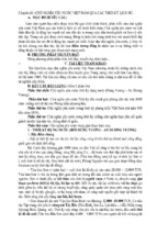
Front cover: Ken Grossman, SEMA Construction of Nichols Reservoir
Rocky Mountain Geo-Conference 2018 GPP 12
iii
Preface
Downloaded from ascelibrary.org by RMIT UNIVERSITY LIBRARY on 01/03/19. Copyright ASCE. For personal use only; all rights reserved.
Since 1984, the ASCE Geo-Institute Chapter of the Colorado Section, in
collaboration with the Mile High Chapter of the Association of Environmental and
Engineering Geologists and the Colorado Association of Geotechnical Engineers, has
organized a biennial series of conferences on a wide variety of geotechnical and
geologic themes that are attended by civil/geotechnical engineers, geologists, and other
geo-professionals. The geotechnical conferences are held at area universities or hotels
and offer the opportunity for sharing ideas and experiences among Colorado’s diverse
geo-disciplines. Since 2004, ASCE’s Geo-Institute has published the papers of these
conferences in a total of eight Geotechnical Practice Publications, allowing the
experiences to be shared with a worldwide audience.
The Steering Committee convened in August 2017 and held monthly meetings to
plan for the 2018 Biennial Rocky Mountain Geo-Conference. The Steering Committee
members included Christoph Goss (Conference Chair), Lindsay Tita (Vice Conference
Chair), James Arthurs, Eric Bergstrom, Mark Brooks, Robin Dornfest, Darin Duran,
Evan Lindenbach, Joels Malama, Cameron Mang, Ryan Marsters, Minal Parekh,
Nicolas Potter, Will Rausch, Robert Redd, Becky Roland, Jere Strickland, Tom Terry,
Nate Thompson, Mark Vessely, Chris Wienecke, and Richard Wiltshire.
Jere Strickland, Richard Wiltshire, and Joels Malama
© ASCE
Rocky Mountain Geo-Conference 2018 GPP 12
Acknowledgments
Downloaded from ascelibrary.org by RMIT UNIVERSITY LIBRARY on 01/03/19. Copyright ASCE. For personal use only; all rights reserved.
The Steering Committee wishes to take this opportunity to thank all of the authors
and reviewers of our papers, which are herein presented as Geotechnical Practice
Publication No. 12. The authors have spent many hours in preparing and finalizing their
papers, which will be presented at the 2018 biennial Rocky Mountain Geo-Conference
on November 2, 2018. These papers have been reviewed by a volunteer group of
Denver area geo-professionals who put in their valuable time and helped make these
papers even better. The Geo-Institute’s Committee on Technical Publications
completed its review of our papers in a very timely manner and their adherence to our
aggressive publication schedule is greatly appreciated. We would also like to
acknowledge the assistance of Donna Dickert, ASCE’s Acquisitions Editor and Diane
Swecker, Senior Technical Manager, Geo-Institute of ASCE, for putting this
publication together. Last but not least, we would like to thank and acknowledge the
sponsors and exhibitors of this year's conference. Without their support, we would not
be able to offer the incredible experience that the Rocky Mountain Geo-Conference has
become known for.
© ASCE
iv
Rocky Mountain Geo-Conference 2018 GPP 12
v
Downloaded from ascelibrary.org by RMIT UNIVERSITY LIBRARY on 01/03/19. Copyright ASCE. For personal use only; all rights reserved.
Contents
Pikes Peak: Subsurface Conditions and New Summit Visitor Center
Foundation Design .................................................................................................................... 1
Joel A. Sloan, William Hoffmann, and Jack Glavan
Landslide Analysis with Incomplete Data: Examples from Colorado
and Wyoming .......................................................................................................................... 15
Paul Santi
Laboratory Evaluation of Post-Fire Ground Treatment ....................................................... 26
Kayla N. Moden, Taylor H. Ray, and Christopher A. Bareither
Interrelationships of Taxonomic and Chemical Properties of Colorado Soils...................... 42
Robert A. Stewart
Internal Erosion of Embankments: A Review and Appraisal ............................................... 61
Bryant A. Robbins and D. V. Griffiths
Clear Lake Dam Replacement: RCC Dam on a Challenging Soil Foundation .................... 76
Greg J. Monley, Steve Jamieson, Henry (Sonny) Buczek, and Don Lopez
Calibration Models Reveal Stability Concerns at Marshall Lake Dam ................................ 88
Ryan Schoolmeesters
Outlet Structure Drain Systems at Twin Lakes and Sugar Loaf Dams .............................. 103
Eric Bergstrom
Gravel Pit Reservoirs: State of Practice and Geotechnical Lessons Learned ..................... 117
Adam Prochaska, Robert Huzjak, and Edwin Friend
Design and Construction of a Tunnel through Dipping Bedrock ........................................ 131
Ryan Marsters and Robin Dornfest
Conduit No. 16 Replacement—A River Tunneled under Your Feet ................................... 144
Nate Soule, Heather Stewart, Jim Light, Mike Gossett, and Randy Parks
Foamed Sand Backfilling for Subsidence Mitigation at Glenrock, Wyoming .................... 151
David S. Hallman
Empirical Solution for Estimating California Bearing Ratio of Wyoming Soils ................ 168
Kasey D. Jones and Bryce Roberts
Innovative Use of Soil Mixing for U.S. 34, Big Thompson Canyon Flood
Recovery ................................................................................................................................ 181
Heather Stewart, Robert Mascarenas, Steve Kuehr, and Ed Lafferty
© ASCE
Rocky Mountain Geo-Conference 2018 GPP 12
Geotechnical Challenges in Reconstruction of Cottonwood Pass Road, Colorado ............. 192
James M. Arthurs
Downloaded from ascelibrary.org by RMIT UNIVERSITY LIBRARY on 01/03/19. Copyright ASCE. For personal use only; all rights reserved.
Fossil Creek Pedestrian Tunnel ............................................................................................ 207
Lance Heyer, John Beckos, and Robin Dornfest
© ASCE
vi
Rocky Mountain Geo-Conference 2018 GPP 12
Pikes Peak: Subsurface Conditions and New Summit Visitor Center Foundation Design
Joel A. Sloan, P.E., M.ASCE1; William Hoffmann, P.E., M.ASCE2; and Jack Glavan, P.E.3
Downloaded from ascelibrary.org by RMIT UNIVERSITY LIBRARY on 01/03/19. Copyright ASCE. For personal use only; all rights reserved.
1
Assistant Professor, U.S. Air Force Academy, Dept. of Civil and Environmental Engineering,
2354 Fairchild Dr., Ste. 6J-165, USAF Academy, CO 80840. E-mail:
[email protected]
2
Senior Principal Engineer and Vice President, CTL Thompson, 5170 Mark Dabling Blvd.,
Colorado Springs, CO 80918. E-mail:
[email protected]
3
Manager, Pikes Peak—America’s Mountain, PO Box 1575, MC 060, Colorado Springs, CO
80901-1575. E-mail:
[email protected]
ABSTRACT
Standing at 14,115 ft above sea level, Pikes Peak is the 31st highest of Colorado’s 54
fourteeners and is one of the most visited mountains in North America. Subsurface conditions at
the summit consist of an active soil layer of in-place weathered Pikes Peak granite subject to
seasonal freeze/thaw cycles, underlain by an intermediate and unstable ice-rich permafrost zone,
followed by bedrock with subfreezing temperatures. The current summit house was constructed
in the early 1960s with a shallow foundation bottomed in the active overburden layer and has
suffered from differential heave and settlement associated with freezing and thawing. Pikes
Peak—America’s Mountain is planning a new summit visitor center to replace the current
facility which will be founded on spread footings bottomed on the lower, massive Pikes Peak
granite. Micro-pile foundations, isolated from the active and ice-rich permafrost zones will
support a series of designated walkways throughout the summit. The purpose of this paper is to
present the subsurface conditions determined by a series of geotechnical investigations in
preparation for the new summit visitor center, document some of the geotechnical challenges
associated with construction on Pikes Peak, and describe the proposed geotechnical solutions to
be incorporated in the summit complex design.
INTRODUCTION
Standing at 14,115 ft above sea level, Pikes Peak is the 31 st highest of Colorado’s 54
fourteeners. Pikes Peak is one of the most visited mountains in North America and is a top tourist
destination in Colorado with an estimated 750,000 visitors annually. A paved road to the summit
makes the mountain accessible to both young and old, to those in good health and to many with
disabilities. The Broadmoor Pikes Peak Cog Railway began service to the peak from Manitou
Springs in 1891 and is also a convenient way for many to visit the peak.
The land at the summit above the 14,000 ft contour is part of Pike National Forest under the
administration of the US Forest Service (USFS) and is listed as a National Historic Landmark.
The Pikes Peak Highway, the Summit House, and other summit infrastructure is operated and
maintained by Pikes Peak – America’s Mountain (PPAM), an enterprise of the City of Colorado
Springs, via a special use permit from the USFS.
The top of the peak is relatively level but has been graded at various points in its history to
accommodate access roads, parking areas, and facility construction. The existing Summit House
is located in the northeast quadrant of the developed area and consists of a one-story building.
There are also three other small one-story structures, the Overlook/Plant building in the southeast
quadrant, the Colorado Springs Utilities building in the south-central area and the US Army High
Altitude Research Lab (HARL) in the west-central portion of the developed mountain top. The
© ASCE
1
Rocky Mountain Geo-Conference 2018 GPP 12
Downloaded from ascelibrary.org by RMIT UNIVERSITY LIBRARY on 01/03/19. Copyright ASCE. For personal use only; all rights reserved.
tracks for the Cog Railway traverse the east crest, terminating at the existing Summit House.
Undeveloped boulder fields exist in the central portions of the mountain top and to the west of
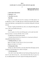
the loop access road. Figure 1 shows the locations of these features.
FIGURE 1. Current Development on Pikes Peak (Colorado Springs 2018)
Subsurface conditions generally consist of alpine permafrost over bedrock, the specific
details of which will be discussed in significant detail later in this paper. The conditions are
similar to Arctic or Antarctic permafrost over bedrock situations (CRREL 2017) although they
are somewhat unique in Colorado due to the presence of permafrost only at high altitudes.
The existing Summit House was constructed in the early 1960’s using a reinforced concrete
mat over a steel beam grid supported by a fill pad that consisted of 3 ft of densely compacted
sand and gravel. The building began experiencing differential settlements early in its life due to
the heat within the structure melting the permafrost below. Some of the settlements over time
were extensive enough that the structure could not be occupied temporarily until repairs were
made.
Due to the age and foundation problems of the current facility, coupled with the desire to
provide an improved visitor experience at the summit, PPAM is planning a new 39,180 square
foot Summit Visitor Center to replace the current facility. The stated goal of the design team is to
“find the perfect balance between a dynamic building that presents a clear destination to visitors
and a minimalist structure deferential to the Peak and its majestic views” (Colorado Springs
2018).
GEOLOGIC SETTING
The summit of Pikes Peak is approximately 15 miles west of Colorado Springs. Pikes Peak is
part of the Pikes Peak Granite batholith with an exposed area of approximately 1,200 square
miles (3,100 km2) (Tweto 1980). The batholith is bounded on the east by the Rampart Range and
Ute Pass faults and intrudes into older granites and metamorphic rock on its other boundaries
© ASCE
2
Rocky Mountain Geo-Conference 2018 GPP 12
Downloaded from ascelibrary.org by RMIT UNIVERSITY LIBRARY on 01/03/19. Copyright ASCE. For personal use only; all rights reserved.
(Smith et al. 1999, Carroll and Crawford 2000, Thorson et al. 2001, Keller et al. 2005). It extends
from southern Colorado Springs up to the latitude of Castle Rock in the north, and extends
approximately 40 miles west of the fault zones on its eastern boundary. Based on the results of
aeromagnetic mapping, as much as half of the batholith area may be unexposed beneath the
ground surface (Noblett et al. 1987).
TABLE 1. Annual Weather Summary at Pikes Peak, 1874 to 1888, After HLA (1987)
Parameter
Mean
Max
Min
Total precipitation (in.)
29.7
44.6
9.4
Average maximum temperature (°F)
26
29
25
Average temperature (°F)
20
22
18
Average minimum temperature (°F)
13
16
11
Average wind speed (mph)
21
22
19
Average barometric pressure (in.
17.75
17.79 17.72
mercury)
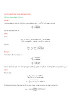
FIGURE 2. Pikes Peak Average Daily Temperature
Finlay (1916) was one of the first to describe and map the geology of the Pikes Peak region.
He described the Pikes Peak Granite as “remarkably uniform in texture and composition
throughout large areas,” noting that the “mesh of coarse interlocking grains is easily ruptured by
frost, and the rock goes to pieces by disintegration, forming a characteristic angular gravel that is
widely distributed as a mantle on long, low divides.” Pikes Peak granite is a coarse-grained
granite composed of alkalic feldspar, quartz and biotite; its color, mostly light pink, is due to the
abundance of the feldspar (Finlay 1916). Noblett et al. (1987) described the granite as a coarse-
© ASCE
3
Rocky Mountain Geo-Conference 2018 GPP 12
grained, red granular rock composed of potassium feldspar, quartz and biotite. Frost action is the
dominant geologic process whereby the Pikes Peak granite weathers to soil.
Downloaded from ascelibrary.org by RMIT UNIVERSITY LIBRARY on 01/03/19. Copyright ASCE. For personal use only; all rights reserved.
CLIMATE
The weather on Pikes Peak is cold, icy, windy, and generally unforgiving. The US Army
Signal Corps operated a weather station on the peak from 1873 to 1888. The station operated
from an 18 ft x 30 ft structure, the first permanent structure on the peak. A portion of this
structure still remains on the peak and is noted as the Historic Summit House Wall in Figure 1.
Table 1 contains the annual weather data measured by the station from January 1874 to June
1888. The station recorded an extreme temperature high of 64 °F on July 19, 1879, an extreme
temperature low of -39 °F on December 21, 1887, along with the highest 1-hour wind speed of
112 mph (May 11, 1881), highest 24-hour wind speed of 71 mph (Sep 28-29, 1878), and the
highest monthly average wind speed of 39 mph in January, 1887 (HLA 1987).
More recent weather measurements support the data from the late 1800s. Figure 2 shows the
average daily temperature over several recent years, illustrating that the mean daily temperature
is below freezing for all but a few months of the year. The mean annual temperature based on
this data is approximately 23.2 °F or -4.9 °C.
Winds are predominantly from the West-Southwest and can be quite high. The average wind
speed at the summit is 17 miles per hour from 195 degrees and the maximum wind speed
recorded in recent years is 70 miles per hour from 358 degrees (Colorado Springs 2018).
PERMAFROST TERMINOLOGY AND FOUNDATION DESIGN CONSIDERATIONS
The subsurface conditions on Pikes Peak are generally described as alpine permafrost over
the Pikes Peak Granite bedrock. Permafrost refers to ground, including both soil and rock, which
remains at or below freezing temperatures for at least two years, regardless of whether water or
ice is present. The permafrost table refers to the shallowest depth at which permafrost occurs and
the permafrost layer or zone refers to the thickness of ground with temperatures below freezing.
When located in a high-altitude environment, the permafrost is called alpine or mountain
permafrost.
Latitude related permafrost typically occurs at latitudes of 50° N and greater in North
America (Bierman and Montgomery (2014) and covers as much as 50 percent of Canada (Harris
et al. 1998). Alpine permafrost is commonly found in the Alps (Haeberli 1992, Bommer et al.
2010) but is relatively rare in the lower 48 US states. Péwé (1983) estimated approximately
38,600 mi2 (100,000 km2) of alpine permafrost in the Western US from Washington to Arizona.
In Colorado’s Front Range, alpine permafrost begins to occur at altitudes ranging from 11,500 ft
(3,500 m) (Ives and Fahey (1971) to 12,500 ft (3,800 m) (Bierman and Montgomery (2014).
Permafrost is thaw-stable if it does not experience thaw settlement or significant loss of
strength when thawed whereas thaw-sensitive permafrost (generally ice-bearing or ice-rich) is
subject to thaw settlement and loss of strength due to melting of the pore ice. The active layer or
zone is the soil above the perennial frozen ground (permafrost) that is subject to seasonal
freezing and thawing (Harris et al. 1998).
Shallow foundations are subject to both frost heave and thaw settlement when supported in
the active zone. Design of deep foundations penetrating the active and permafrost zones is
governed by the presence of the ice in the soil rather than by the soil-pile interaction in
traditional geotechnics (Biggar and Kong 2009). The bond strength between the frozen soil and
pile, or adfreeze, plays an important role in the performance of the pile and the behavior tends to
© ASCE
4
Downloaded from ascelibrary.org by RMIT UNIVERSITY LIBRARY on 01/03/19. Copyright ASCE. For personal use only; all rights reserved.
Rocky Mountain Geo-Conference 2018 GPP 12
be time-dependent (i.e. governed by creep) and also subject to volume changes (heave and
settlement) if the ice and water surrounding the pile freezes or thaws.
Physical characteristics and mechanical properties of frozen soil tend to be highly spatially
variable and extremely sensitive to changes in temperature (Noetzli and Gruber 2009). Icy layers
tend to be concentrated near the permafrost table and construction of embankments or structures
can significantly alter the location and condition of the permafrost table due to warmth from a
heated structure or insulating properties of an embankment (Wei et al 2009), as well as
redistribution of snow drifts by wind blowing around a structure and shadows cast from a
structure (Haeberli 1992). For all of these reasons, the subsurface investigation and knowledge of
the temperature variation within the soil is extremely important to design of foundations in
permafrost (Wei et al. 2009, Bommer et al. 2010).
Design approaches in areas underlain by permafrost depend on the stability of the permafrost
layer. If the soil or bedrock is thaw-stable, the presence of the permafrost can be ignored and
traditional geotechnical design methods may be employed (Harris et al. 1998). In thaw-sensitive
permafrost, the designer selects an active or passive approach. A passive approach maintains the
permafrost in a frozen condition generally through ventilation or insulation, or some combination
of the two (Harris et al. 1998, Wei et al. 2009, Bommer et al. 2010). Ventilation requires space
under the structure for cold air to circulate and maintain the permafrost in a cryotic state,
whereas, the insulation approach requires thick fill with or without synthetic insulation to prevent
warming of the thaw-sensitive permafrost. The active approach calls for thawing and compaction
of, or complete replacement, of thaw-sensitive materials. Alternatively, the foundations and
structure may be designed to withstand the predicted thaw settlements (Harris et al. 1998).
CURRENT SUMMIT HOUSE FOUNDATION PROBLEMS
The current Summit House is a one-story facility constructed in 1963 with plan dimensions
of approximately 65 ft by 178 ft. The initial plans for the facility called for a 6-ft thick fill of
crushed rock on which to place the foundation in a passive design approach to keep the ice-rich
permafrost below the foundation from thawing. Due to cost considerations and difficulty in
excavation during the initial construction, the 6 ft of fill was reduced to 3 ft and on-site fill was
substituted for the crushed rock (HLA 1987). A 3-inch thick foam insulation layer was added
beneath the foundation to compensate for the reduced quantity of fill, and the fill pad thickness
varied with location due to the difficulty in excavation. The foundation itself consists of a 6-inch
thick, reinforced concrete mat underlain by steel beam grid embedded within the fill and
structurally connected to the mat. The resulting design was a hybrid approach with the reinforced
mat with steel beam grid designed to resist some degree of differential settlement and the
reduced quantity of fill and foam insulation in an attempt to prevent the freezing temperatures
from reaching the foundation (HLA 1987).
Construction of the facility on top of the permafrost layer created a zone of warmth which
melted portions of the permafrost, leading to settlement of the underlying soil and significant
gaps in some locations under the mat foundation. Harding Lawson Associates (HLA 1987)
reported gaps of a few inches to several feet and differential settlement of the mat foundation of
up to 8.5 inches. HLA also reported periodic upward movement of the foundation due to the
formation of ice lenses and also due to jacking of the foundation in some locations to restore
support. In a few of the early winters of its use, the heat was shut off to the facility which likely
contributed to refreezing of soil underneath the facility and frost jacking. The facility currently
has jacks under the floor system to keep it level and the subfloor system is inspected annually.
© ASCE
5
Rocky Mountain Geo-Conference 2018 GPP 12
Downloaded from ascelibrary.org by RMIT UNIVERSITY LIBRARY on 01/03/19. Copyright ASCE. For personal use only; all rights reserved.
Nevertheless, foundation problems and maintenance costs, combined with the desire for an
improved visitor experience, necessitate the construction of a replacement facility.
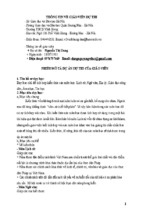
FIGURE 3. Locations of Borings and Test Pits in the Vicinity of the New Summit Visitors
Center (CTL Thompson 2016)
SUBSURFACE INVESTIGATION
Woodward-Clyde completed the initial foundation report in 1957 that was used as the basis
of the current summit house design. An addition to the summit house was considered in 1972
and Chen and Associates completed a subsurface investigation and report that recommended the
addition be constructed on drilled shafts. The addition was never built, but the site investigation
was used for the construction of the sewage maintenance facility built in 1974 to 1975, which is
founded primarily on drilled shafts bottomed in the intact granite, although some of the structure
was supported by shallow foundations bottomed in the active layer (HLA 1996). The structure is
performing satisfactorily where supported on drilled shafts but experienced problems where
supported by shallow foundations (CTL Thompson 2016a).
Harding-Lawson and Associates completed an investigation in 1986 with a report dated
1987. The purpose of the report was to investigate the foundation problems of the current summit
house and recommend foundation repair alternatives. CTL Thompson completed an investigation
in 1995 with a report dated January 1996, for the primary purpose of constructing a new summit
visitor center. Within the 1996 CTL Thompson report, Dr Louis Goldberg analyzed the thermal
© ASCE
6
Rocky Mountain Geo-Conference 2018 GPP 12
Downloaded from ascelibrary.org by RMIT UNIVERSITY LIBRARY on 01/03/19. Copyright ASCE. For personal use only; all rights reserved.
properties of the soil on the peak (Goldberg 1995).
TABLE 2. Rock Core Data for the Planned Visitor Center (USACE 2015a/b, 2016)
Boring
Permafrost
Top of
Core
Core
Number
Depth (ft)
Bedrock (ft)
Interval (ft) Recovery (ft)
RQD
10.7 – 19.0
8.0
78%
PK 15-01
6
13.3
19.0 – 26.0
7.0
90%
26.0 – 32.8
6.8
46%
11.0 – 20.0
8.8
90%
PK 15-02
6
9.0
20.0 – 30.0
10.2
98%
11.5 – 20.0
8.5
84%
PK 15-03
7
10.5
20.0 – 29.6
9.6
100%
10.0 – 20.0
9.3
87%
PK 16-01
7.6
10.0
20.0 – 30.0
10.1
85%
30.0 – 35.9
5.9
90%
10.7 – 20.7
9.7
63%
PK 16-02
7.2
10.7
20.7 – 30.0
9.3
95%
30.0 – 38.5
8.5
100%
FIGURE 4. Generalized Subsurface Profile at the Summit of Pikes Peak
Plans for the summit visitor center in the late-90s were postponed and the US Army Corps of
Engineers (USACE) conducted a series of subsurface investigations in 2015 and 2016 when
PPAM revitalized planning for the new summit house. USACE conducted eleven borings on the
summit of Pikes Peak in late summer of 2015 (USACE 2015a/b). Two additional borings were
drilled and cored in June 2016 (USACE 2016). CTL Thompson completed a series of reports
based on these subsurface investigations and other historic data (CTL Thompson 2015, 2016a/b).
Figure 3 is a partial site plan of the summit showing the locations of borings and test pits relevant
© ASCE
7
Rocky Mountain Geo-Conference 2018 GPP 12
Downloaded from ascelibrary.org by RMIT UNIVERSITY LIBRARY on 01/03/19. Copyright ASCE. For personal use only; all rights reserved.
to the planned facilities.
FIGURE 5. Subsurface Temperatures by a) HLA (1987), b) CTL Thompson (1996), and c)
USACE (2015 a/b)
FIGURE 6. Aerial View of Proposed Development (Colorado Springs 2018)
© ASCE
8
Downloaded from ascelibrary.org by RMIT UNIVERSITY LIBRARY on 01/03/19. Copyright ASCE. For personal use only; all rights reserved.
Rocky Mountain Geo-Conference 2018 GPP 12
FIGURE 7. Bedrock and Shallow Foundation Cross-section (RTA Architects 2018)
The subsurface investigations are in general agreement that the upper 6 ft or so of the
subsoils consist of random combinations of silty and clayey sand and gravel with varying
percentages of cobble to small boulders. Investigators also agree that the materials below upper
soils consist of similar materials but in a frozen water matrix, i.e. ice-rich permafrost. HLA
(1987) and CTL Thompson (2015) note ice lenses of approximately 1 foot in thickness within
the permafrost.
The more significant variance between the HLA and USACE (2015a/b, 2016) investigations
relates to the depth or thickness of the ice-rich permafrost layer. All the investigators agreed the
underlying materials are very strong Pikes Peak Granite. HLA (1996) suggests the depth of the
ice-rich permafrost may extend to depths as great as 16 ft. Given the issues at the existing
Summit House, this depth of permafrost seemed reasonable at the time HLA did their work.
Work by USACE suggests the ice-rich permafrost layer to be only 1 to 4.5 ft in thickness.
The surficial Pikes Peak Granite was severely fractured in many of the USACE borings and
may be indicative of ice fracturing. Fracture angles varied from 0 to 90 degrees but most were 0
to 50 degrees. Fractures contained tight apertures. Fractures that were not tight were narrow to
extremely narrow. The upper fractured bedrock likely has ice in it and gets more competent and
less icy with depth. Table 2 shows the core recovery and rock quality designation (RQD) for
some boring locations in Figure 3 in the vicinity of the new summit visitor center by USACE
(2015a/b, 2016), illustrating the lower RQDs in the surficial granite in some locations. The
pneumatic drilling method employed by USACE may have masked the occurrence of thin ice
lenses as the borehole was flushed with hot air, potentially melting thinner ice lenses.
Considering the fractured zone is actually ice-bearing permafrost, the depths would correlate
with the depths reported by HLA (1987).
Although not presented in this paper, CTL Thompson (2016b) developed five cross-sections
of subsurface profiles at the summit based on all of the subsurface information available, noted
as A to F in Figure 3. Figure 4 shows a simplified subsurface profile based on these cross-
© ASCE
9
Rocky Mountain Geo-Conference 2018 GPP 12
Downloaded from ascelibrary.org by RMIT UNIVERSITY LIBRARY on 01/03/19. Copyright ASCE. For personal use only; all rights reserved.
sections.
FIGURE 8. Foundation Detail (RTA Architects 2018)
HLA (1987), CTL Thompson (1996) and USACE (2015a/b) measured subsurface
temperatures in test pits or boreholes. Figure 5 shows this data taken at various seasons over a
period of three decades. Important conclusions from these data are:
All measurements indicate subfreezing temperatures at just a few feet below ground
surface at various times throughout the year.
Temperatures in certain time periods are only slightly below freezing indicating the
sensitive nature of the permafrost (“depth of frost” of only 1 or 2 degrees Fahrenheit).
Even a small increase in temperature could result in melting and significant settlement
due to melting. Observations by Goldberg (1995) support this conclusion.
The temperatures of the various subsurface materials are less than 32 ºF to depths in
excess of 20 ft and the exact depth where the temperature is above freezing is unknown.
Based on a ground temperature monitoring program supplemented with information
collected from engineering and mining operations, Ives and Fahey (1971) report that
permafrost depth at locations above 14,000 ft in the Niwot Ridge west of Boulder
© ASCE
10
Rocky Mountain Geo-Conference 2018 GPP 12
Colorado can exceed 200 ft (60 m).
Downloaded from ascelibrary.org by RMIT UNIVERSITY LIBRARY on 01/03/19. Copyright ASCE. For personal use only; all rights reserved.
NEW SUMMIT VISITOR CENTER
Multiple design concepts for the Summit Visitor Center were considered at various locations
on the summit. The option selected for the Summit Visitor Center is a three-level structure cut
into the hillside on the southeast side of the summit, overlooking Colorado Springs as shown in
Figure 6. The entrance at the grade of the access loop road to the north of the building will have
a footprint of about 1,981 ft 2 at an elevation of 14,102 ft. The main level will consist of about
25,000 ft2 of space at elevation 14,085 ft. Most of the roof will be accessible for visitors to walk
on and enjoy the surrounding views. The main level will contain concessionary services, a dining
area, exhibit area, and restrooms. The main level will walk out to the south to various
observation decks. The lower area will lay mainly along the rear of the north wall and below the
west one-third of the main level. This lower area will be at elevation 14,073 ft. and contain
potable water storage tanks, wastewater tanks or treatment tanks, a digester, and utility service
areas below the west one-third. The lower level will also contain a one-vehicle garage.
Heat from facility is highly likely to melt the ice-rich permafrost layer. HLA (1987)
recommended drilled shafts consisting of steel H-piles or closed-end pipe piles with end plates
set in predrilled holes and backfilled with concrete. Installation would include excavation of all
overburden material and drilling the 24-inch shafts from the bedrock surface with 8 ft of bedrock
penetration. As an alternative to drilled shafts, CTL Thompson (1996) considered small diameter
drilled and grouted pipe or H-piles (micropiles) and recommended a test program to hone in on
the most efficient design. Goldberg (1995) recommended these deep foundation elements be
cased in PVC through the icy ground to break the bond between the pile and the ice.
CTL Thompson (2016) reviewed these prior foundation recommendations and concluded the
most economic foundation alternative to be shallow foundations supported on the intact Pikes
Peak Granite. Figure 7 shows one of the facility cross-sections with the shallow foundations
from the 75 percent design (RTA Architects 2018). As the building footprint progresses to the
south, the excavation will be deepened so that the continuous and square spread footings bear on
the intact granite rather than the active zone. Foundation walls will be insulated precast concrete
panels and floors on the lowest level of the facility will be slab-on-grade. Below the floors, the
permafrost layer will be removed and replaced with 3-inch minus, crushed bedrock fill. Exterior
slabs will be structurally supported with micro-piles as will the elevated walkway abutments.
Some exterior entry slabs will also have voids beneath them to accommodate frost heave.
Adequate drainage is critically important as runoff trapped in the overburden layer could add
to the ice-rich permafrost layer and contribute to increased frost jacking and/or thaw settlement
(CTL Thompson 1996, Goldberg 1995). The foundations will include exterior drains at footing
elevations where significant fills are placed as shown in the drawing detail in Figure 8 (RTA
Architects 2018). Some below-grade foundations on the interior of the facility will also have
interior drains.
Cuts as deep as 26 ft below ground surface will be required and excavation will be
challenging (CTL Thompson 2015). The upper, unfrozen, materials can likely be excavated
using conventional heavy duty excavation equipment (CTL Thompson 2015). Based on previous
observations in excavating the test pits (CTL Thompson 1996), removal of the ice-rich materials
near the permafrost table will likely be more difficult than excavation at lower elevations in
frozen ground. Excavation into the Pikes Peak Granite will require pre-splitting or blasting (CTL
Thompson 2015).
© ASCE
11
Downloaded from ascelibrary.org by RMIT UNIVERSITY LIBRARY on 01/03/19. Copyright ASCE. For personal use only; all rights reserved.
Rocky Mountain Geo-Conference 2018 GPP 12
The elevated walkways on the summit shown in Figure 6 will be supported by micropiles. A
critical consideration is the curing and bonding of the grout to the supporting rock, which will
exist at temperatures below freezing (CTL Thompson 2016). Installation by the subcontractor
will likely need to include preheating of the drill hole, reinforcing rod and grout mix
constituents, as well as admixtures, to ensure proper curing and bonding before the grout freezes
(Bommer et al. 2010, CTL Thompson 2016). Bommer et al. (2010) suggest that anchor boreholes
be flushed with air rather than with fluids and anchors should be placed as soon as practical in
order to prevent degradation of the surrounding permafrost and a quality bond. The micropiles
will be socketed into the granite bedrock and a sleeve will be installed through the active later to
insulate them from frost jacking or thaw settlement of adjacent ground.
SUMMARY AND CONCLUSIONS
This paper describes the climate and geologic setting of Pikes Peak, foundation issues
associated with frost heave and thaw settlement at the current Summit House, and subsurface
conditions at the summit in preparation for construction of a new Summit Visitor Center. The
subsurface conditions consist of an active layer of weathered Pikes Peak Granite, approximately
6 ft in thickness. The active layer is underlain by an ice-rich permafrost layer that is underlain by
Pikes Peak Granite bedrock, the surface of which is significantly fractured in some locations.
The depth of the permafrost layer is unknown. The current summit house shallow foundations
are bottomed in the active layer and have performed poorly. For this reason, foundations for the
new facility will be reinforced concrete spread footings bearing on the granite bedrock. Adequate
drainage is critically important to avoid freezing runoff water from contributing to frost heave of
the facility. Foundations will be surrounded by free-draining fill materials and exterior drains
will facilitate movement of the water away from the facility. A series of designated walkways at
the summit will be supported on micropiles socketed in the bedrock with sleeves through the
active layer to prevent frost jacking. Special consideration will be given to the grout mix design
and installation procedures to ensure adequate curing and bonding with the bedrock at
subfreezing temperatures. Construction for the new facility is anticipated to begin in the summer
of 2018.
DISCLAIMER
The views expressed in this paper are those of the authors and do not necessarily reflect the
official policy or position of the United States Air Force Academy, the Air Force, the
Department of Defense, or the U.S. Government.
REFERENCES
Biggar,K.W., and Kong, V. (2001). “Analysis of the long-term pile load tests in permafrost from
the Short Range Radar site foundations.” Can. Geotech. J. 88: 441–460.
Bierman, P.R. and Montgomery, D.R. (2014). Key Concepts in Geomorphology. W. H. Freeman
and Company Publishers.
Bommer, C., Phillips, M., and Arenson, L.U. (2010). “Practical recommendations for planning,
constructing, and maintaining infrastructure in mountain permafrost.” Permafrost and
Periglacial Processes. 21: 97–104.
Carroll, C. J. and T. A. Crawford (2000) Geologic map of the Colorado Springs quadrangle, El
Paso County Colorado, Colorado Geological Survey Open-File Report OF-00-3, scale
© ASCE
12
Downloaded from ascelibrary.org by RMIT UNIVERSITY LIBRARY on 01/03/19. Copyright ASCE. For personal use only; all rights reserved.
Rocky Mountain Geo-Conference 2018 GPP 12
1:24,000.
Cold Regions Research and Engineering Laboratory (CRREL). (2017). “Permafrost Conditions,
new Summit House – Pikes Peak, CO.” Memo addressed to Jack Glavan, Pikes Peak –
America’s Mountain. 5 pgs.
Colorado Springs (2018). Pikes Peak Summit Complex Project Links:
https://parks.coloradosprings.gov/pikes-peak-americas-mountain/page/summit-complexproject-links
CTL Thompson. (1996). “Geotechnical evaluation: New Pikes Peak summit house, El Paso
County, Colorado.” Report for the Colorado Springs Dept of Transportation, 30 pgs.
CTL Thompson. (2015). “Preliminary geotechnical evaluation: Pikes Peak summit house,
Colorado Springs, Colorado.” Report prepared for PPAM by CTL Thompson, Inc. 189 pgs.
CTL Thompson. (2016a). “Geotechnical evaluation: Pikes Peak summit house, Colorado
Springs, Colorado.” Report prepared for PPAM by CTL Thompson, Inc. 118 pgs.
CTL Thompson. (2016b). “Supplemental subsurface information: Pikes Peak summit house.”
Report prepared for PPAM by CTL Thompson, Inc. 40 pgs.
Finlay, G.I. (1916). Colorado Springs, Colorado: USGS Geologic Atlas, Folio 203.
Goldberg, L.F. (1995). “Pike’s Peak geotechnical survey: soil thermal property results.” Report
for the Pike’s Peak Hospitality Building Project, 12 pgs.
Haeberli, W. (1992). “Construction, environmental problems and natural hazards in periglacial
mountain belts.” Permafrost and Periglacial Processes. Vol 3: 111–124.
Harris, S.A., French, H.M., Heginbottom, J.A., Johnston, G.H., Ladanyi, B., Sego, D.C., and van
Everdingen, R.O. (1998). “Glossary of permafrost and related ground ice terms.” Technical
Memorandum No. 142, report of the Permafrost Subcommittee, Associate Committee on
Geotechnical Research, National Research Council of Canada. 154 pgs.
Harding-Lawson and Associates (HLA). (1987). “Geotechnical and structural engineering
evaluation of Pikes Peak summit house.” Report prepared for City of Colorado Springs
Department of Public Works.” 72 pgs.
Ives, J.D. and Fahey, B.D. (1971). “Permafrost occurrence in the front range, Colorado Rocky
Mountains, U.S.A.” Journal of Glaciology. 10(38): 105–111.
Keller, J., C. Siddoway, M. Morgan, E. Route, M. Grizzell, R. Sacerdoti, and A. Stevenson.
(2005). Geologic map of the Manitou Springs 7.5-minute quadrangle, El Paso and Teller
counties, Colorado: Colorado Geological Survey, Denver, Colorado, 41 pgs.
Noblett, J.B., Cohen, A.S., Leonard, E.M., Loeffler, B.M., Gevirtzman, D.A. (1987). “The
Garden of the Gods and basal Phanerozoic nonconformity in and near Colorado Springs,
Colorado.” Geological Society of America Centennial Field Guide – Rocky Mountain
Section. Vol 2, 335–338.
Noetzli, J. and Gruber, S. (2009). “Transient thermal effects in Alpine permafrost.” The
Cryosphere. 3: 85–99.
Péwé, T.L. (1983). “Alpine permafrost in the contiguous United States: A review.” Arctic and
Alpine Research. 15(2): 145–156.
RTA Architects (2018). “Pikes Peak Summit Complex: 75% Construction Documents.” 171 pgs.
Smith, D.R., Noblett, J., Wobus, R.A., Unruh, D., and Chamberlain, K.R. (1999). “A review of
the Pikes Peak batholith, Front Range, central Colorado: A ‘type example’ of A-type granitic
magmatism.” Rocky Mountain Geology. 34(2): 289–312.
Thorson, J., Carroll, C. and Morgan, M. (2001). Geologic Map of the Pikeview Quadrangle, El
Paso County: Colorado Geological Survey, Denver, p. 3–6.
© ASCE
13