MINISTRY OF EDUCATION AND TRAINING
HANOI UNIVERSITY OF SCIENCE AND TECHNOLOGY
DO VIET HA
MÔ HÌNH ĐẶC TÍNH KÊNH TRUYỀN
CHO THÔNG TIN THỦY ÂM VÙNG NƯỚC NÔNG
CHANNEL MODELING FOR SHALLOW
UNDERWATER ACOUSTIC COMMUNICATIONS
DOCTORAL THESIS OF TELECOMMUNICATIONS ENGINEERING
HA NOI - 2017
MINISTRY OF EDUCATION AND TRAINING
HANOI UNIVERSITY OF SCIENCE AND TECHNOLOGY
DO VIET HA
MÔ HÌNH ĐẶC TÍNH KÊNH TRUYỀN
CHO THÔNG TIN THỦY ÂM VÙNG NƯỚC NÔNG
CHANNEL MODELING FOR SHALLOW
UNDERWATER ACOUSTIC COMMUNICATIONS
Specialization: Telecommunications Engineering
Code No: 62520208
DOCTORAL THESIS OF TELECOMMUNICATIONS ENGINEERING
SUPERVISORS:
1. Assoc.Prof. Van Duc Nguyen
2. Dr. Van Tien Pham
Hanoi - 2017
DECLARATION OF AUTHORSHIP
I hereby declare that this dissertation titled, "Channel Modeling for Shallow Underwater Acoustic Communications”, and the work presented in
it are entirely my own original work under the guidance of my supervisors. I confirm that:
• This work was done wholly or mainly while in candidature for a PhD
research degree at Hanoi University of Science and Technology.
• Where any part of this dissertation has previously been submitted
for a degree of any other qualification at Hanoi University of Science
and Technology or any other institution, this has been clearly stated.
• Where I have consult the published work or others, this is always
given. With the exception of such quotations, this dissertation is
entirely my own work.
• I have acknowledged all main source of help.
• Where the thesis is based on work done by myself jointly with others, I have made exactly what was done by others and what I have
contributed myself.
SUPERVISORS
Hanoi, August 27, 2017
PhD STUDENT
1. Assoc.Prof. Van Duc Nguyen
2. Dr. Van Tien Pham
Do Viet Ha
ACKNOWLEDGEMENTS
First and foremost, I would like to thank my advisor Associate Prof.
Dr. Nguyen Van Duc for for providing an excellent atmosphere for doing
research, for his valuable comments, constant support and motivation.
His guidance helped me in all the time of research and writing of this
dissertation. I could not have imagined having a better advisor and
mentor for my PhD.
I would also like to thank Dr. Pham Van Tien for their advice and
feedback, also for many educational and inspiring discussions.
My sincere gratitude goes to the members in the Wireless Communication Lab, School of Electronics and Telecommunications, Hanoi University of Science and Technology, Hanoi, Vietnam. Without their support
and friendship it would have been difficult to complete my PhD studies.
I am also thankful to Dr. Nguyen Tien Hoa for his invaluable instructions in presenting my dissertation.
I would also like to express my deepest gratitude to my parents, my
husband, my son, and my daughter. They were always supporting me
and encouraging me with their best wishes, they were standing by me
throughout my life.
Hanoi, August 27, 2017
PhD STUDENT
Do Viet Ha
Contents
TABLE OF CONTENTS . . . . . . . . . . . . . . . . . . . . . . . . . . . . . . . . . . . .
ABBREVIATIONS . . . . . . . . . . . . . . . . . . . . . . . . . . . . . . . . . . . . . .
iv
LIST OF FIGURES . . . . . . . . . . . . . . . . . . . . . . . . . . . . . . . . . . . . .
vi
LIST OF TABLES . . . . . . . . . . . . . . . . . . . . . . . . . . . . . . . . . . . . . . .
ix
INTRODUCTION . . . . . . . . . . . . . . . . . . . . . . . . . . . . . . . . . . . . . . .
1
Chapter 1. DESIGN OF SHALLOW UWA CHANNEL SIMULATORS . . . . . . . . . . . . . . . . . . . . . . . . . . . . . . . . . . . . . . . . . . . . . 15
1.1. Introduction . . . . . . . . . . . . . . . . . . . . . . . . . . . . . . . . . . . . . . . . . . . . . . .
16
1.2. Overview of Simulation Models for UWA Channels . . . . . . . .
1.2.1. Rayleigh and Rice channels . . . . . . . . . . . . . . . . . . . . . . . . . . . . .
1.2.2. Deterministic SOS Channel Models . . . . . . . . . . . . . . . . . . . . .
1.2.3. Deterministic SOC Channel Models. . . . . . . . . . . . . . . . . . . . .
19
19
20
21
1.3. The Geometry-based UWA Channel Simulator . . . . . . . . . . . . . 21
1.3.1. Developing the Reference Model from the Geometrical Channel
Model . . . . . . . . . . . . . . . . . . . . . . . . . . . . . . . . . . . . . . . . . . . . . . . . . . . . . . . 22
1.3.2. The Simulation Model . . . . . . . . . . . . . . . . . . . . . . . . . . . . . . . . . . 27
1.3.3. The Estimated Parameters of the Simulation Model . . . . 27
1.3.4. Simulation Results . . . . . . . . . . . . . . . . . . . . . . . . . . . . . . . . . . . . . 28
1.4. The Measurement-based UWA Channel Simulator . . . . . . . . . .
1.4.1. The Reference Model from the Measurement Data . . . . . .
1.4.2. The Simulation Model . . . . . . . . . . . . . . . . . . . . . . . . . . . . . . . . .
1.4.3. Estimated Channel Parameters of the Simulation Model
1.4.4. Comparison of the Two Channel Simulators . . . . . . . . . . . .
28
29
32
33
34
1.5. The Proposed Approach for the Static UWA Channel . . . . . .
1.5.1. Descriptions . . . . . . . . . . . . . . . . . . . . . . . . . . . . . . . . . . . . . . . . . . . .
1.5.2. Results and Discussions . . . . . . . . . . . . . . . . . . . . . . . . . . . . . . . .
35
36
38
i
ii
1.6. The Proposed Approach for the Case of Doppler Effects . . . .
1.6.1. The Measurement Data. . . . . . . . . . . . . . . . . . . . . . . . . . . . . . . . .
1.6.2. The Conventional Measurement-based Simulators . . . . . . .
1.6.3. The Proposed Channel Simulator . . . . . . . . . . . . . . . . . . . . . . .
39
40
41
45
1.7. Conclusions . . . . . . . . . . . . . . . . . . . . . . . . . . . . . . . . . . . . . . . . . . . . . . . .
50
Chapter 2. MODELING OF DOPPLER POWER SPECTRUM
FOR SHALLOW UWA CHANNELS . . . . . . . . . . . . . . . . . . . . 53
2.1. Introduction . . . . . . . . . . . . . . . . . . . . . . . . . . . . . . . . . . . . . . . . . . . . . . .
53
2.2. The Proposed Doppler Spectrum Model . . . . . . . . . . . . . . . . . . . .
2.2.1. The Doppler Effects in Shallow UWA Channels . . . . . . . . .
2.2.2. The Proposed Doppler Model for UWA Channels . . . . . . .
56
56
59
2.3. The Description of Doppler Spectrum Measurements . . . . . . .
2.3.1. Experimental Setup . . . . . . . . . . . . . . . . . . . . . . . . . . . . . . . . . . . .
2.3.2. Measurement Scenarios . . . . . . . . . . . . . . . . . . . . . . . . . . . . . . . . .
2.3.3. Reference Model from the Measurement Data . . . . . . . . . . .
63
63
64
66
2.4. Parameter Optimizations of the Proposed Model . . . . . . . . . . .
67
2.5. Measurement and Doppler Modeling Results . . . . . . . . . . . . . . .
2.5.1. Scenario 1 . . . . . . . . . . . . . . . . . . . . . . . . . . . . . . . . . . . . . . . . . . . . . .
2.5.2. Scenario 2 . . . . . . . . . . . . . . . . . . . . . . . . . . . . . . . . . . . . . . . . . . . . . .
2.5.3. Scenario 3 . . . . . . . . . . . . . . . . . . . . . . . . . . . . . . . . . . . . . . . . . . . . . .
68
69
71
75
2.6. Conclusions . . . . . . . . . . . . . . . . . . . . . . . . . . . . . . . . . . . . . . . . . . . . . . . .
77
Chapter 3. UWA-OFDM SYSTEM PERFORMANCE ANALYSIS USING THE MEASUREMENT-BASED UWA CHANNEL MODEL. . . . . . . . . . . . . . . . . . . . . . . . . . . . . . . . . . . . . .. . . . 78
3.1. Introduction . . . . . . . . . . . . . . . . . . . . . . . . . . . . . . . . . . . . . . . . . . . . . . .
79
3.2. ICI Analysis of UWA-OFDM Systems . . . . . . . . . . . . . . . . . . . . . .
3.2.1. SIR Calculation . . . . . . . . . . . . . . . . . . . . . . . . . . . . . . . . . . . . . . . .
3.2.2. Ambient Noise Power . . . . . . . . . . . . . . . . . . . . . . . . . . . . . . . . . . .
3.2.3. SINR Calculation. . . . . . . . . . . . . . . . . . . . . . . . . . . . . . . . . . . . . . .
81
82
83
84
3.3. Capacity Calculation . . . . . . . . . . . . . . . . . . . . . . . . . . . . . . . . . . . . . . .
86
iii
3.4. Numerical Results . . . . . . . . . . . . . . . . . . . . . . . . . . . . . . . . . . . . . . . . . .
3.4.1. The SIR . . . . . . . . . . . . . . . . . . . . . . . . . . . . . . . . . . . . . . . . . . . . . . . .
3.4.2. The SINR . . . . . . . . . . . . . . . . . . . . . . . . . . . . . . . . . . . . . . . . . . . . . .
3.4.3. Channel Capacity . . . . . . . . . . . . . . . . . . . . . . . . . . . . . . . . . . . . . .
3.4.4. Transmit Power . . . . . . . . . . . . . . . . . . . . . . . . . . . . . . . . . . . . . . . .
87
88
89
90
92
3.5. Chapter Conclusions . . . . . . . . . . . . . . . . . . . . . . . . . . . . . . . . . . . . . . .
96
CONCLUSIONS . . . . . . . . . . . . . . . . . . . . . . . . . . . . . . . . . . . . . . . .
99
APPENDIX . . . . . . . . . . . . . . . . . . . . . . . . . . . . . . . . . . . . . . . . . . .
103
LIST OF PUBLICATIONS. . . . . . . . . . . . . . . . . . . . . . . . . . . . .
105
ABBREVIATIONS
ACF
Autocorrelation Function
AOA
Angles of Arrival
AOD
Angles of Departure
AWGN
Additive White Gaussian Noise
BPSK
Binary Phase Shift Keying
CIR
Channel Impulse Response
FCF
Frequency Correlation Function
ICI
Inter-Channel Interference
INLSA
Iterative Nonlinear Least Square Approximation
ISI
Inter-Symbol Interference
LNA
Low Noise Amplifier
LOS
Line of Sight
LPNM
Lp-Norm Method
MESS
Method of Equally Spaced Scatterers
MSE
Mean Square Error
OFDM
Orthogonal Frequency Division Multiplexing
PDF
Probability Density Function
PDP
Power Delay Profile
PN
Pseudo-Noise
PSD
Power Spectra Density
Rx
Receiver
SINR
Signal to Interference plus Noise Ratio
SIR
Signal-to-Interference Ratio
SNR
Signal to Noise Ratio
SOC
Sum-of-Cisoids
SOS
Sum-of-Sinusoids
TCF
Time Correlation Function
iv
v
T-FCF
Time-Frequency Correlation Function
TVCIR
Time Variant Channel Impulse Response
TVCTF
Time-Variant Channel Transfer Function
Tx
Transmitter
UWA
Underwater Acoustic
WLAN
Wireless Local Area Network
WSSUS
Wide-Sense Stationary Uncorrelated Scattering
List of Figures
1
Multipath interference in UWA communication systems. . . . . . . . . . . 4
1.1
The methodology behind the geometry-based channel modelling [17, 55]. . 17
1.2
The methodology behind the measurement-based channel modelling [31, 56]. 18
1.3
The scheme of designing the geometry-based channel simulator [17, 55]. . . 22
1.4
The geometrical model for shallow UWA channels with randomly distributed scatterers Si,n (•) on the surface (i = 1) and the bottom (i = 2)
[55]. . . . . . . . . . . . . . . . . . . . . . . . . . . . . . . . . . . . . . . . 23
1.5
The comparison between the normalized FCF of the reference model and
that obtained by the geometry-based simulator. . . . . . . . . . . . . . . . 29
1.6
1.7
Illustration of the measurement setup in Halong bay. . . . . . . . . . . . . 30
ˆ
The measured |h(τ, t)|2 for the transmission distance of 150 m. . . . . . . 31
1.8
The measured and normalized PDP ρ(τ ) obtained for the transmission
distance of 150 m.
1.9
. . . . . . . . . . . . . . . . . . . . . . . . . . . . . . . 32
The comparison of the normalized FCF obtained by the two simulators
to that of the reference model. . . . . . . . . . . . . . . . . . . . . . . . . . 35
1.10 The flowchart of proposed approach to design the static UWA channel
simulator. . . . . . . . . . . . . . . . . . . . . . . . . . . . . . . . . . . . . 36
1.11 The comparison between the normalized FCF of the reference model and
that obtained by the measurement-based, the geometry-based, and the
proposed simulators. . . . . . . . . . . . . . . . . . . . . . . . . . . . . . . 38
1.12 The normalized Doppler power spectrum. . . . . . . . . . . . . . . . . . . . 41
1.13 a) The reference T-FCF derived from the measurement results. b) The
T-FCF of the channel simulation model designed by the conventional
simulator. . . . . . . . . . . . . . . . . . . . . . . . . . . . . . . . . . . . . 43
1.14 The comparison between the normalized T-FCF of the reference model
and that obtained by the conventional measurement-based simulator. . . . 44
1.15 The flowchart of the proposed approach for the case of moving Rx.
vi
. . . . 46
vii
1.16 a) The reference T-FCF derived from the measurement results. b) The
T-FCF of the channel simulation model designed by the proposed simulator. 48
1.17 The comparison between the normalized T-FCF of the reference model
and that obtained by the proposed simulator. . . . . . . . . . . . . . . . . 49
1.18 a) The error of the simulation T-FCF designed by the conventional
measurement-based simulator. b)The error of the simulation T-FCF
designed by the proposed simulator. . . . . . . . . . . . . . . . . . . . . . . 51
2.1
The 3-D geometry model for shallow environments with randomly distributed scatterers Si,n (•) on the surface (i = 1) and the bottom (i = 2). . 57
2.2
The Spike-shape Doppler spectrum. . . . . . . . . . . . . . . . . . . . . . . 61
2.3
Effect of the two Doppler components on the overall Doppler spectrum. . . 62
2.4
Illustration of the measurement setup in Halong bay. . . . . . . . . . . . . 64
2.5
The Doppler measurement scenario 1. . . . . . . . . . . . . . . . . . . . . . 64
2.6
The Doppler measurement scenario 2. . . . . . . . . . . . . . . . . . . . . . 65
2.7
The Doppler measurement scenario 3. . . . . . . . . . . . . . . . . . . . . . 65
2.8
The steps of parameter computations. . . . . . . . . . . . . . . . . . . . . . 68
˜
The reference model Sn (f ) compared with the proposed Doppler model
2.9
S (f ) for four observed cases in scenario 1. . . . . . . . . . . . . . . . . . . 73
˜
2.10 The reference model Sn (f ) compared with the proposed Doppler model
S (f ) for six typical cases in scenario 2. . . . . . . . . . . . . . . . . . . . . 74
˜
2.11 The reference model Sn (f ) compared with the proposed Doppler model
S (f ) for six cases in scenario 3. . . . . . . . . . . . . . . . . . . . . . . . . 76
2.12 The estimated trajectory movement of the Rx for scenario 3. . . . . . . . . 77
3.1
Average SIR versus signal bandwidth for different numbers of sub-carriers.. 88
3.2
Average SINR versus signal bandwidth for different numbers of sub-carriers. 89
3.3
Capacity of UWA-OFDM system versus signal bandwidth for different
numbers of sub-carriers. . . . . . . . . . . . . . . . . . . . . . . . . . . . . 91
3.4
Average spectra efficiency versus signal bandwidth for the number of
sub-carriers N = 256, and SNR = 20 dB at the receiver. . . . . . . . . . . . 92
3.5
Required transmit power PT versus signal bandwidth to achieve an SNR
of 20 dB at the receiver. . . . . . . . . . . . . . . . . . . . . . . . . . . . . 93
3.6
Average spectra efficiency versus SNR at the receiver for the number of
sub-carriers N = 256, and signal bandwidth B = 10 kHz. . . . . . . . . . . 94
viii
3.7
Average SIR, SINR versus SNR at the receiver for the number of subcarriers N = 256, and signal bandwidth B = 10 kHz. . . . . . . . . . . . . . 94
3.8
Average spectra efficiency versus SNR at the receiver for the number of
sub-carriers N = 256, and signal bandwidth B = 10 kHz. . . . . . . . . . . 95
3.9
Average SIR, SINR, SNR versus transmit power for the number of subcarriers N = 256, and signal bandwidth B = 10 kHz. . . . . . . . . . . . . . 96
3.10 Noise power, average ICI power, and average desired signal power versus
transmit power for the number of sub-carriers N = 256, and signal
bandwidth B = 10 kHz. . . . . . . . . . . . . . . . . . . . . . . . . . . . . . 97
3.11 Cumulative distribution function of the SNR, SIR, and SINR of subcarriers for N = 256, and signal bandwidth B = 10 kHz. . . . . . . . . . . . 97
3.12 Results of Doppler spectrum measurement and modeling while the Rx
moves with the consistent speed of VR = 0.5 m/s. . . . . . . . . . . . . . . 104
List of Tables
1.1
Parameters of the geometrical channel model . . . . . . . . . . . . . . . . . 29
1.2
The performance comparisons . . . . . . . . . . . . . . . . . . . . . . . . . 39
1.3
The performance comparison of the simulation approaches. . . . . . . . . . 50
2.1
Environmental conditions and system configurations of experiment . . . . . 63
2.2
The optimal and derivative parameters of the proposed model.
2.3
The optimal parameters for Doppler spectrum modeling derived from
. . . . . . 70
the measurement data in scenario 1 (as plotted in Fig. 2.9.) . . . . . . . . 72
2.4
The optimal parameters for Doppler spectrum modeling derived from
the measurement data in scenario 2 (as plotted in Fig. 2.10). . . . . . . . . 72
2.5
The optimal parameters for Doppler spectrum modeling derived from
the measurement data in scenario 3 (as plotted in Fig. 2.11). . . . . . . . . 76
3.1
System specification . . . . . . . . . . . . . . . . . . . . . . . . . . . . . . 88
ix
INTRODUCTION
1. Overview of the Dissertation
Underwater acoustic (UWA) communication systems have been developed for the past three decades [25]. They can be used in potential applications such as environmental monitoring, offshore oil exploration, and
military missions. Nevertheless, UWA communications have a plethora
of difficulties, so they display many challenges for further developments.
The reason can be explained by a large demand on high frequency utilization as well as high data rate access under very complexity shallow
underwater environments. All these requirements, without doubt, call
for intensive research efforts on how to cope with problems faced by
current UWA communications, e.g., limited availability of acoustic frequency spectrum, complex time variations in UWA fading channels, and
urgent needs for good quality of service. Therefore, this dissertation is
devoted to investigate UWA communication systems by considering all
these challenges. In particular, two goals are aimed at, which are known
as: i) UWA channel modeling and ii) performance analysis of UWA
communication systems
The design, development, performance analysis, and test of such communication systems, however, call for a deep insight of the most important characteristics of real-world propagation environments. Similar to
the other communication fashions, channel modeling is an initial investigation because it provides hints to predict performance of communication systems before doing further high cost implementations as hardware
designs [75, 96]. The task of channel modeling is to reproduce the real
channel conditions. In other words, the statistical properties of the real
channel such as path loss, multipath fading and Doppler effect should
be represented by channel modeling. For this reason, this dissertation
presents the analysis and modeling UWA channels in shallow water en1
2
vironments, which have strong multipath and Doppler effects on signal
propagations [97].
Without discussing the performance of UWA communication systems
under different propagation environments, this study seems to be unfinished. In this view point, Orthogonal Frequency Division Multiplexing
(OFDM) has been widely applied to acoustic transmission [10, 22, 42, 68,
86] since it can mitigate inter-symbol interference as well as has higher
spectral efficiency than single carrier systems. Thus, for the sake of
completeness, we utilize analyses such as the signal-to-interference ratio
(SIR), the signal-to-interference-plus-noise ratio (SINR), and the channel capacity to determine the performance of the UWA-OFDM systems.
We believe that the performance assessment reported here bridges the
gap between the derived UWA channel models and their impact on the
performance of the deployed UWA communication systems.
This chapter presents the general concepts in UWA channel modeling and a brief introductions to UWA channel characteristics. Moreover,
the motivations and the major contributions of this dissertation are highlighted in the remainder of this chapter.
2. Characteristics of Shallow Underwater Acoustic Channels
The physical characteristics of UWA propagation environments are very
different from those of terrestrial ones with electromagnetic waves. UWA
channels can be characterized by three main aspects [12, 30, 88]: the high
transmission loss depending on signal frequencies, the time-varying multipath propagation, and the low transmit speed of sound in water (about
1500m/s). The fast time variations of UWA channels are mainly caused
by the relative movement [88], internal waves [32], and surface waves
[16, 82]. These features make UWA channels the most difficult communication media in use today [88], and give rise to critical challenges for
further developments.
Acoustic Frequency
The frequency of underwater acoustics is in the range from 10 Hz to
1 MHz [92]. When the bandwidth is between 10÷20 percent of the center
of signal, the communication system is called wide-band. Although the
3
bandwidth of UWA communication systems is small, the signal frequency
is also small. Thus, UWA communication systems are wide-band due to
the low relative center frequency in comparison with the bandwidth [88].
Transmission Loss
The transmission loss of UWA propagation significantly depends on
the signal frequency. The three factors that attenuate UWA signals
include spreading loss, absorption loss, and scattering loss. The overall
path loss A (l, f ) is defined as [88]
l k
l−l
A (l, f ) =
α(f ) r ,
lr
where f is the signal frequency and l is the transmission distance, taken
in reference to some lr . The symbol k is the path loss exponent, which
model the spreading loss and its value are usually between 1 and 2.
The absorption coefficient α(f ), which increases rapidly with signal frequency, can be obtained using an empirical formula [20].
Noise
Noise in UWA channels consists of ambient noise and site-specific
noise. Ambient noise is always present in the background of the sea,
while site-specific noise is unique to certain places. The first one is
often modeled as Gaussian and it is not white, while the latter one contains significant non-Gaussian components. The power spectral density
of ambient noise decays at a rate of approximately 18 dB/decade. The
attenuation growing with frequency whereas the noise decays with frequency, result in a signal-to-noise ratio (SNR) that varies over the signal
bandwidth [88].
Propagation Delay
The speed of UWA waves increases with the salinity, temperature, and
pressure of the water. In shallow water environments, the temperature
and pressure are almost unchanging; thus, the speed of sound in shallow water is considered to be a constant value (about 1500 m/s). The
propagation delay τ can then be obtained as
d
τ=
c
where d and c are the propagation distance (in meters) and the speed
4
of sound (in m/s), respectively. Because of the low speed of sound, the
propagation delay τ = d/c is about tens milliseconds for transmission
distances of longer than ten meters.
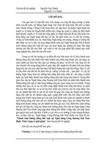
Multipath
In shallow water environments, the propagation of sound appears to
be a complicated multipath, which is mainly caused by reflections at the
surface and bottom. The multipath interference in UWA communication
systems is illustrated in Fig. 1. Each path has its propagation delay
depending on its geometry. The maximal propagation delay is called
as the delay spread of the UWA channel. Because of the multipath
effect, the received signal is composed of various paths with different
amplitudes, propagation delays, and phase shifts.
Figure 1: Multipath interference in UWA communication systems.
Doppler Effect
Another characteristic of UWA channels is time varying, which is
caused by two factors. The first one is the result of the relative movement
between the transmitter (Tx) and the receiver (Rx), while the latter one
is caused by inherent changes in the transmission medium such as the
changes in weather, surface wave, and storm, etc [9].
A relative movement between Tx/Rx or a moving medium results in
the change of frequency of the acoustic waves, which is called as Doppler
shift. An expression for the maximum Doppler frequency shift fD,max is
given by [19]
v
fD,max = fc ,
c
5
where fc and c are the transmitted signal frequency (i.e. carrier frequency) and the sound speed, respectively; v stands for the speed of the
observer.
The magnitude of Doppler effect is determined by the ratio a = v/c
named as the relative Doppler shift, which is significant to the carrier
frequency due to the low speed of sound. The non-negligible Doppler
shift is a distinctive characteristic of UWA channels in comparison with
the radio channel.
Moreover, even without intentional movements, the inherent changes
in transmission medium such as waves or drifts of transducers also lead
to the Doppler shift. In shallow water environments, reflections from the
surface are the main reason of time-variant UWA channels. The Doppler
spread presents the spectral width spreading of the received signal, which
depends on the wave height, wind speed, reflections from the surface and
bottom of the sea.
3. UWA Channel Modeling Approaches and the State-of-the-Art
The characteristics of UWA channels are very complex due to Doppler
effects, high attenuations depending on signal frequencies, multipath effects, and additive color noises. Therefore, it is very difficult to model
exactly UWA channels, especially in shallow underwater environments,
which have strong multipath effects on the signal. UWA channel modeling is not new research in underwater communication systems. However,
over the past few decades, although large variety of UWA channel models
have been proposed, there is still no typical model that can be applied for
all UWA channels because of differences in geographical areas, weather
conditions, and seasonal cycles [24, 70, 73, 88, 93, 96]. Recent approaches
of designing UWA simulators in literatures are classified into two main
categories, which are the geometry and the measurement-based.
The UWA geometry-based simulator has been designed by using the
geometrical channel model. The well-known Bellhop code [69] is one of
popular examples of this simulator. The code built the UWA channel
simulator by using the ray theory for a given geometry, but it did not
6
consider the random channel variation [75]. To deal with this issue,
some studies run the Bellhop model in combination with environment
conditions, such as temperature and salinity [89], wind speeds [28], and
surface shapes [37]. The simulated UWA channels obtained through
such Bellhop channel simulator showed the statistical properties that
are similar to those of the real UWA channels in some experimental
scenarios. The difficulty of specifying the environment conditions is one
of the limitations of this simulator.
Another kind of the UWA geometry-based simulator is developed by
combining the ray theory with statistical methods to describe the UWA
propagation environment [13, 17, 27, 55, 73, 75, 103, 104]. The statistical properties of the UWA channel were analyzed by using the probability density function (PDF) of the angle-of-arrival (AOA), and the
angle-of-departure (AOD) as key parameters. The AOD is, however,
a derivative parameter of the AOA [55]. In some research studies, the
PDFs of the AOAs are assumed to be normally [103, 104] or uniformly
[75] distributed. Besides, in [13], the author approximated the PDF of
AOA with the half-circular Rice PDF. The geometry-based simulator
can describe the overall UWA channel with fewer estimated channel parameters than the measurement-base one, and it is feasible to extend
from one transmission environment to others without significant efforts.
However, the geometrical modeling is not able to provide the statistical
characteristics of the simulated channel, which is close to those of the
real UWA channel. This is because of the time and spatially varying
characteristics of the shallow UWA propagation environments.
The UWA measurement-based channel modeling approach have been
investigated in [24, 74, 76, 85, 105]. Almost all of these channel simulators are developed from given measurement data, which are obtained
from a specific underwater environment. Based on analyzing the measurement data, the distribution of the propagation paths are specified
such as Rayleigh [24, 85], Rician [76], K-distributed [105], and lognormal [74]. Furthermore, in the replay-based simulators [58, 83, 95],
the time variant channel impulse responses (TVCIRs) of the measured
UWA channel can be reproduced; or a new random TVCIR can be gener-
7
ated so that its statistical properties are similar to those of the measured
channel. The measurement-based simulator does not require physical input parameters, which may not be easy to set. In addition, the simulated
channels obtained by this simulator are extremely realistic based on actual measurement data. The disadvantage of the measurement-based
simulator is that it can be only applied to the specific transmission environment, where the channel is measured. The best way to expand the
diversity of this simulator is to collect a large amount of measurement
data at different time and locations [84]. Moreover, for designing the
measurement-based channel simulator, a large number of channel parameters, including path gains, Doppler frequencies, propagation delays,
and phase shifts need to be estimated [56]. There are some efficient
computation algorithms to estimate these parameters, such as the rotational invariance techniques (ESPRIT) [34], the space-alternating generalized expectation-maximization (SAGE) [33], the iterative nonlinear
least square approximation (INLSA) [31], the Lp -Norm Method (LPNM)
[59]. The measurements and computation efforts to estimate the large
number of channel parameters make the measurement-based simulator
more complex than the geometry-based one.
In Vietnam, despite of a growing need of UWA communication applications in the military and commerce, there is not many research
papers on UWA communication, especially in the field of channel modeling [2, 3, 6]. Some characteristics of UWA propagations in Vietnam sea
have been investigated in some earlier research [1, 4, 5, 7, 8]; however,
the results of UWA channel modeling have not been given. In [6], the authors have simulated the UWA propagation rays by solving the Eikonal
equation for given environmental conditions. As mentioned above, these
environmental parameters are hard to be specified due to the complexity
of UWA propagation environments. Besides, the simulated UWA propagation rays is time-invariant that may not be able to describe the real
UWA channel in most of cases.
4. Goals of the Dissertation
This dissertation aims at developing accurate and efficient approaches of
- Xem thêm -