Laboratory Exercise 10
In Laboratory Exercise 9 we described a simple processor. In Part I of that exercise the processor itself was
designed, and in Part II the processor was connected to an external counter and a memory unit. This exercise
describes subsequent parts of the processor design. Note that the numbering of figures and tables in this exercise
are continued from those in Parts I and II in the preceding lab exercise.
Part III
In this part you will extend the capability of the processor so that the external counter is no longer needed, and
so that the processor has the ability to perform read and write operations using memory or other devices. You
will add three new types of instructions to the processor, as displayed in Table 3. The ld (load) instruction loads
data into register RX from the external memory address specified in register RY. The st (store) instruction stores
the data contained in register RX into the memory address found in RY. Finally, the instruction mvnz (move if
not zero) allows a mv operation to be executed only under a certain condition; the condition is that the current
contents of register G are not equal to 0.
Operation
Function performed
ld Rx,[Ry]
Rx ← [[Ry]]
st Rx,[Ry]
[Ry] ← [Rx]
mvnz Rx, Ry
if G != 0, Rx ← [Ry]
Table 3. New instructions performed in the processor.
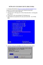
A schematic of the enhanced processor is given in Figure 7. In this figure, registers R0 to R6 are the same
as in Figure 1 of Laboratory Exercise 9, but register R7 has been changed to a counter. This counter is used
to provide the addresses in the memory from which the processor’s instructions are read; in the preceding lab
exercise, a counter external to the processor was used for this purpose. We will refer to R7 as the processor’s
program counter (PC), because this terminology is common for real processors available in the industry. When
the processor is reset, PC is set to address 0. At the start of each instruction (in time step 0) the contents of PC
are used as an address to read an instruction from the memory. The instruction is stored in IR and the PC is
automatically incremented to point to the next instruction (in the case of mvi the PC provides the address of the
immediate data and is then incremented again).
The processor’s control unit increments PC by using the incr_PC signal, which is just an enable on this counter.
It is also possible to directly load an address into PC (R7) by having the processor execute a mv or mvi instruction
in which the destination register is specified as R7. In this case the control unit uses the signal R7 in to perform
a parallel load of the counter. In this way, the processor can execute instructions at any address in memory, as
opposed to only being able to execute instructions that are stored in successive addresses. Similarly, the current
contents of PC can be copied into another register by using a mv instruction. An example of code that uses the
PC register to implement a loop is shown below, where the text after the % on each line is just a comment. The
instruction mv R5,R7 places into R5 the address in memory of the instruction sub R4,R2. Then, the instruction
mvnz R7,R5 causes the sub instruction to be executed repeatedly until R4 becomes 0. This type of loop could be
used in a larger program as a way of creating a delay.
mvi
mvi
mv
sub
mvnz
R2,#1
R4,#10000000
R5,R7
R4,R2
R7,R5
% binary delay value
% save address of next instruction
% decrement delay count
% continue subtracting until delay count gets to 0
1
Bus
16
16
incr_pc
R7 in
R0
16
16
A in
Counter
(R7)
A
Clock
DIN
AddSub
16
Addsub
ADDR
R0 in
E
L
ADDR
DOUT
16
DOUT
16
G in
Multiplexers
G
8
16
9
DIN out
R0 out
} R7
G out
out
IR in
ADDR in
IR
DOUT in
9
Control unit
W_D
W
Run
Resetn
Done
3
Clear
Counter
Figure 7. An enhanced version of the processor.
Figure 7 shows two registers in the processor that are used for data transfers. The ADDR register is used to
send addresses to an external device, such as a memory module, and the DOUT register is used by the processor to
provide data that can be stored outside the processor. One use of the ADDR register is for reading, or fetching, instructions from memory; when the processor wants to fetch an instruction, the contents of PC (R7) are transferred
across the bus and loaded into ADDR. This address is provided to memory. In addition to fetching instructions,
the processor can read data at any address by using the ADDR register. Both data and instructions are read into the
processor on the DIN input port. The processor can write data for storage at an external address by placing this
address into the ADDR register, placing the data to be stored into its DOUT register, and asserting the output of
the W (write) flip-flop to 1.
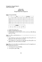
Figure 8 illustrates how the enhanced processor is connected to memory and other devices. The memory unit
in the figure supports both read and write operations and therefore has both address and data inputs, as well as a
write enable input. The memory also has a clock input, because the address, data, and write enable inputs must be
2
loaded into the memory on an active clock edge. This type of memory unit is usually called a synchronous random
access memory (synchronous RAM). Figure 8 also includes a 16-bit register that can be used to store data from the
processor; this register might be connected to a set of LEDs to allow display of data on the DE2 board. To allow
the processor to select either the memory unit or register when performing a write operation, the circuit includes
some logic gates that perform address decoding: if the upper address lines are A 15 A14 A13 A12 = 0000, then the
memory module will be written at the address given on the lower address lines. Figure 8 shows n lower address
lines connected to the memory; for this exercise a memory with 128 words is probably sufficient, which implies
that n = 7 and the memory address port is driven by A 6 . . . A0 . For addresses in which A 15 A14 A13 A12 = 0001,
the data written by the processor is loaded into the register whose outputs are called LEDs in Figure 8.
A 12
}
A 15
Processor
ADDR
DOUT
Memory
4
16
n
16
addr
data
DIN
q
16
wr_en
W
Done
A 12
}
Resetn
Run
4
A 15
Clock
E
Resetn
16
Run
D
Q
LEDs
Figure 8. Connecting the enhanced processor to a memory and output register.
1. Create a new Quartus II project for the enhanced version of the processor.
2. Write Verilog code for the processor and test your circuit by using functional simulation: apply instructions
to the DIN port and observe the internal processor signals as the instructions are executed. Pay careful
attention to the timing of signals between your processor and external memory; account for the fact that the
memory has registered input ports, as we discussed for Figure 8.
3. Create another Quartus II project that instantiates the processor, memory module, and register shown in Figure 8. Use the Quartus II MegaWizard Plug-In Manager tool to create the ALTSYNCRAM memory module.
Follow the instructions provided by the wizard to create a memory that has one 16-bit wide read/write data
port and is 128 words deep. Use a MIF file to store instructions in the memory that are to be executed by
your processor.
4. Use functional simulation to test the circuit. Ensure that data is read properly from the RAM and executed
by the processor.
5. Include in your project the necessary pin assignments to implement your circuit on the DE2 board. Use
switch SW17 to drive the processor’s Run input, use KEY 0 for Resetn, and use the board’s 50 MHz clock
signal as the Clock input. Since the circuit needs to run properly at 50 MHz, make sure that a timing
constraint is set in Quartus II to constrain the circuit’s clock to this frequency. Read the Report produced by
the Quartus II Timing Analyzer to ensure that your circuit operates at this speed; if not, use the Quartus II
tools to analyze your circuit and modify your Verilog code to make a more efficient design that meets the
3
50-MHz speed requirement. Also note that the Run input is asynchronous to the clock signal, so make sure
to synchronize this input using flip-flops.
Connect the LEDs register in Figure 8 to LEDR 15−0 so that you can observe the output produced by the
processor.
6. Compile the circuit and download it into the FPGA chip.
7. Test the functionality of your design by executing code from the RAM and observing the LEDs.
Part IV
In this part you are to connect an additional I/O module to your circuit from Part III and write code that is executed
by your processor.
Add a module called seg7_scroll to your circuit. This module should contain one register for each 7-segment
display on the DE2 board. Each register should directly drive the segment lights for one 7-segment display, so
that the processor can write characters onto these displays. Create the necessary address decoding to allow the
processor to write to the registers in the seg7_scroll module.
1. Create a Quartus II project for your circuit and write the Verilog code that includes the circuit from Figure 8
in addition to your seg7_scroll module.
2. Use functional simulation to test the circuit.
3. Add appropriate timing constraints and pin assignments to your project, and write a MIF file that allows
the processor to write characters to the 7-segment displays. A simple program would write a word to the
displays and then terminate, but a more interesting program could scroll a message across the displays, or
scroll a word across the displays in the left, right, or both directions.
4. Test the functionality of your design by executing code from the RAM and observing the 7-segment displays.
Part V
Add to your circuit from Part IV another module, called port_n, that allows the processor to read the state of
some switches on the board. The switch values should be stored into a register, and the processor should be able
to read this register by using a ld instruction. You will have to use address decoding and multiplexers to allow the
processor to read from either the RAM or port_n units, according to the address used.
1. Draw a circuit diagram that shows how the port_n unit is incorporated into the system.
2. Create a Quartus II project for your circuit, write the Verilog code, and write a MIF file that demonstrates
use of the port_n module. One interesting application is to have the processor scroll a message across the 7segment displays and use the values read from the port_n module to change the speed at which the message
is scrolled.
3. Test your circuit both by using functional simulation and by downloading it and executing your processor
code on the DE2 board.
Suggested Bonus Parts
The following are suggested bonus parts for this exercise.
1. Use the Quartus II tools to identify the critical paths in the processor circuit. Modify the processor design
so that the circuit will operate at the highest clock frequency that you can achieve.
2. Extend the instructions supported by your processor to make it more flexible. Some suggested instruction
types are logic instructions (AND, OR, etc), shift instructions, and branch instructions. You may also wish
to add support for logical conditions other than “not zero” , as supported by mvnz, and the like.
3. Write an Assembler program for your processor. It should automatically produces a MIF file from assembler
code.
c
Copyright �2005
Altera Corporation.
4
- Xem thêm -