See discussions, stats, and author profiles for this publication at: https://www.researchgate.net/publication/267038900
Investigation of Cylinder Deactivation (CDA)
Strategies on Part Load Conditions
Article in SAE Technical Papers · October 2014
DOI: 10.4271/2014-01-2549
CITATIONS
READS
3
384
5 authors, including:
Mohd Farid Muhamad Said
Azhar abdul aziz
Universiti Teknologi Malaysia
Universiti Teknologi Malaysia
44 PUBLICATIONS 137 CITATIONS
81 PUBLICATIONS 164 CITATIONS
SEE PROFILE
SEE PROFILE
Zulkarnain Abdul Latiff
Amin Mahmoudzadeh Andwari
Universiti Teknologi Malaysia
University of Tehran
32 PUBLICATIONS 38 CITATIONS
18 PUBLICATIONS 106 CITATIONS
SEE PROFILE
SEE PROFILE
Some of the authors of this publication are also working on these related projects:
Two stroke engine improvement View project
Ethanol Fuelled HCCI engine Development View project
All content following this page was uploaded by Mohd Farid Muhamad Said on 21 October 2014.
The user has requested enhancement of the downloaded file.
Downloaded from SAE International by Universiti Teknologi Malaysia, Sunday, October 19, 2014
Investigation of Cylinder Deactivation (CDA)
Strategies on Part Load Conditions
2014-01-2549
Published 10/13/2014
Mohd Farid Muhamad Said, Azhar Bin Abdul Aziz, Zulkanain Abdul Latiff,
and Amin Mahmoudzadeh Andwari
ADC, Universiti Teknologi Malaysia
Shahril Nizam Mohamed Soid
MSI, Universiti Kuala Lumpur
CITATION: Muhamad Said, M., Abdul Aziz, A., Abdul Latiff, Z., Mahmoudzadeh Andwari, A. et al., "Investigation of Cylinder
Deactivation (CDA) Strategies on Part Load Conditions," SAE Technical Paper 2014-01-2549, 2014, doi:10.4271/2014-01-2549.
Copyright © 2014 SAE International
Abstract
Introduction
Many efforts have been invested to improve the fuel efficiency
of vehicles mainly for the local consumers. One of the main
techniques to have better fuel efficiency is cylinder deactivation
system. In this paper, the main research area is focus on the
investigation of cylinder deactivation (CDA) technology on
common engine part load conditions within common Malaysian
driving condition. CDA mostly being applied on multi cylinders
engines. It has the advantage in improving fuel consumption by
reducing pumping losses at part load engine conditions. Here,
the application of CDA on 1.6 liter four cylinders gasoline
engine is studied. One-dimensional (1-D) engine modeling is
performed to investigate the effect of intake and exhaust valve
strategy on engine performance with CDA. The 1-D engine
model is constructed starts from the air-box cleaner up to
exhaust system according to the 1.6 liter actual engine
geometries. The model is simulated at various engine speeds
with full load condition. The simulated results show that the
constructed model is well correlated to measured data. This
correlated model is then used to investigate the effect of valves
timing configurations on engine performance. The model is
then used to determine the optimum intake and exhaust valve
lift and timing for CDA application at part load conditions. Also,
the effects on the in-cylinder combustion as well as pumping
losses are presented. The study shows that the effects of
valves strategies are very significant on the engine
performance. Pumping losses is found to be reduced, thus
improving fuel consumption and engine thermal efficiency.
Recent technologies for gasoline engines include lean
combustion technologies including direct injection and
homogenous charged compression ignition [1, 2, 3, 4], the
optimizing intake and exhaust valve timing and valve lift [5, 6]
and the cylinder deactivation systems (CDA). These
technologies have been applied to improve the engine efficiency
and reduce the amount of fuel usage. Cylinder deactivation
(CDA) is promising method in reducing fuel consumption and
emission at part load in SI engines [7]. Deactivation of half the
engine cylinders require the remaining firing cylinder to operate
at a higher IMEP (Indicated Mean Effective Pressure) to provide
similar overall BMEP (Brake Mean Effective Pressure) or engine
torque. In other term, the work required by the firing cylinder is
much more than normal operation.
Hence, in order to supply required work with only half the
cylinders, each cylinder needs more air and fuel than it would
with all cylinders firing [8]. Therefore, the intake manifold
pressure must be higher (less throttled), which seriously
reduce the pumping work of the engine [9]. In cylinder
deactivation mode, the combustion chambers of the unfired
cylinders are kept shut by the closed valves. As a result, the
enclosed air works like a pneumatic spring which is periodically
compressed and decompressed without overall pumping work
[10]. Cylinder deactivation creates an effective variable
displacement engine, where the engine provides the optimum
power based on demand with the fuel economy benefits
without sacrifices the overall actual power.
Downloaded from SAE International by Universiti Teknologi Malaysia, Sunday, October 19, 2014
Table 1. Engine technical specifications
Engine Modeling
Model Construction
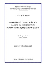
The engine model has been built starts from the intake airbox
system until exhaust tailpipe system (Figure 1). This is to make
sure that the constructed model represents the real engine
condition. For the intake and exhaust systems, almost all
components are modeled as pipes. In GT-Power, pipes are
used to represent these systems as tubes and they are
connected by junctions. The flow model involves the solution of
Navier-Stokes equations, namely the conservation of
continuity, momentum and energy equations. Detail about the
flow model can be referred to GT-Suite manual [11].
In achieving better engine performance, it depends on the
characterization of the technology used. It is important to
understand the details of CDA technology, their interaction and
parameters that effect on engine performance. Therefore, a
one dimensional (1D) fluid dynamic computation simulation is
used to assess the CDA engine performances. Here, software
called GT-Power is applied to construct an engine model of
natural aspirated, 1.6 L CamPro, spark-ignition engine. This 1.6
L engine is used in normal passenger car. The technical
specifications of the engine are listed in Table 1.
Here, the purpose of engine model construction is to
understand the effect of intake and exhaust valves profiles
configuration on CDA engine performance. This paper presents
the model construction, correlation with actual test data and
simulation of engine performance with CDA mode.
In order to model the airbox in the GT-Power environment, a
3D CAD geometry of this component is used. The 3D geometry
is discretized using GEM3D module in GT-Power to convert
into the model file. Inlet and outlet diameters of each pipe
(snorkel, duct, zip-tube) as well as their length are defined in
GT-Power environment. Upper and lower airbox are defined by
their volume. Discharge coefficient is also introduced to
represent pressure losses of the air filter.
A similar discretization process is applied to the intake and
exhaust manifold. Here, the intake and exhaust runners are
modeled using bend pipe object. Basically, this object will take
into account the pressure loss due to the effect of bending
geometry. The diameters of inlet and outlet, as well as the
angle and bending radius are defined to model these runners.
Intake plenum is defined using Y-split part, where the volume
of each runner section is applied.
Methodology
This work focuses on the investigation of intake and exhaust
valve profiles on the performance of CDA mode operation. In
order to achieve that, a one dimensional (1D) engine
simulation tool is used to construct the CDA engine model and
to investigate the effect of intake variables on engine
performance. Before the CDA engine model is constructed,
four cylinder natural aspirated (NA) engine model is developed
and correlated to measured data.
A lot of input data are defined during the engine model
construction. Some of the inputs are engine characteristics,
cylinder geometry, intake and exhaust system geometries, fuel
properties, injector characteristics, valve sizes, ambient
conditions and engine operating conditions. The model is run
at various engine speeds and at wide open throttle (WOT)
conditions. To fully investigate the accuracy and reliability of
the constructed model, the simulated results from the model
are correlated to the measured data. In validation process, the
constructed model is tuned so that the simulated results are
well agreed to measured data. After both results are well
compared, then the model is accepted as correlated model.
This correlated model is then used to simulate the engine
performance with CDA mode operation.
View publication stats
Figure 1. Constructed engine model of four cylinders 1.6 L engine.
The most important step in engine modeling is to use the right
combustion model. A fully-predictive combustion model known
as ‘SI Turbulence’ function is applied. This combustion model
more suitable for the prediction study of part load engine
operation, exhaust gas recirculation (EGR), spark timing effect,
cylinder knocking, combustion chamber design and spark plug
gap [12]. This model predicts the combustion pressure as well
as IMEP and other performances. Input data includes ‘.stl’ file
of combustion chamber geometry, spark timing at each rpm at
wide open throttle (WOT) condition, spark plug location and
gap as well as fuel octane number are defined.
- Xem thêm -