A cement and concrete industry publication
How to Design Concrete
Structures using Eurocode 2
A J Bond MA MSc DIC PhD MICE CEng
O Brooker BEng CEng MICE MIStructE
A J Harris BSc MSc DIC MICE CEng FGS
T Harrison BSc PhD CEng MICE FICT
R M Moss BSc PhD DIC CEng MICE MIStructE
R S Narayanan FREng
R Webster CEng FIStructE
Foreword
The introduction of European standards to UK construction is a significant event. The ten design standards, known
as the Eurocodes, will affect all design and construction activities as current British Standards for design are due
to be withdrawn in 2010 at the latest. BS 8110, however, has an earlier withdrawal date of March 2008. The aim
of this publication is to make the transition to Eurocode 2: Design of concrete structures as easy as possible by
drawing together in one place key information and commentary required for the design and detailing of typical
concrete elements.
The cement and concrete industry recognised that a substantial effort was required to ensure that the UK design
profession would be able to use Eurocode 2 quickly, effectively, efficiently and with confidence. With support
from government, consultants and relevant industry bodies, the Concrete Industry Eurocode 2 Group (CIEG)
was formed in 1999 and this Group has provided the guidance for a co-ordinated and collaborative approach to
the introduction of Eurocode 2. Part of the output of the CIEG project was the technical content for 7 of the 11
chapters in this publication. The remaining chapters have been developed by The Concrete Centre.
Acknowledgements
The content of Chapters 1 and 3 to 8 were produced as part of the project Eurocode 2: transition from UK to
European concrete design standards. This project was part funded by the DTI under the Partners in Innovation
scheme. The lead partner was British Cement Association. The work was carried out under the guidance of the
Concrete Industry Eurocode 2 Group and overseen by a Steering Group of the CIEG (members are listed on inside
back cover).
Particular thanks are due to Robin Whittle, technical editor to the CEN/TC 250/SC2 committee (the committee
responsible for structural Eurocodes), who has reviewed and commented on the contents. Thanks are also due to
John Kelly and Chris Clear who have contributed to individual chapters.
Gillian Bond, Issy Harvey, Kevin Smith and the designers at Media and Design Associates and Michael Burbridge Ltd
have also made essential contributions to the production of this publication.
Published by The Concrete Centre
Riverside House, 4 Meadows Business Park, Station Approach, Blackwater, Camberley, Surrey GU17 9AB
Tel: +44 (0)1276 606800 Fax: +44 (0)1276 606801 www.concretecentre.com
CCIP–006
Published December 2006
ISBN 1-904818-4-1
Price Group P
© The Concrete Centre. Joint copyright with British Cement Association for Chapters 1 and 3 to 8.
Permission to reproduce extracts from British Standards is granted by British Standards Institution.
British Standards can be obtained from BSI Customer Services, 389 Chiswick High Road, London W4 4AL.
Tel: +44 (0)20 8996 9001 email:
[email protected]
CCIP publications are produced on behalf of the Cement and Concrete Industry Publications Forum – an industry
initiative to publish technical guidance in support of concrete design and construction.
CCIP publications are available from the Concrete Bookshop at www.concrete bookshop.com
Tel: +44(0)7004-607777
All advice or information from The Concrete Centre (TCC), British Cement Association (BCA) and Quarry Products Association (QPA) is intended for
those who will evaluate the significance and limitations of its contents and take responsibility for its use and application. No liability (including that for
negligence) for any loss resulting from such advice or information is accepted by TCC, BCA and OPA or their subcontractors, suppliers or advisors. Readers
should note that publications from TCC, BCA and OPA are subject to revision from time to time and should therefore ensure that they are in possession
of the latest version. Part of this publication has been produced following a contract placed by the Department for Trade and Industry (DTI); the views
expressed are not necessarily those of the DTI.
Printed by Michael Burbridge Ltd, Maidenhead.
How to Design Concrete
Structures using Eurocode 2
Contents
1.
Introduction to Eurocodes
1
2.
Getting started
9
3.
Slabs
17
4.
Beams
25
5.
Columns
33
6.
Foundations
43
7.
Flat slabs
51
8.
Deflection calculations
59
9.
Retaining walls
67
10. Detailing
79
11. BS 8500 for building structures
91
How to design concrete structures using Eurocode 2
1. Introduction to Eurocodes
R S Narayanan FREng O Brooker BEng, CEng, MICE, MIStructE
The Eurocode family
This chapter shows how to use Eurocode 21 with the other Eurocodes. In
particular it introduces Eurocode: Basis of structural design2 and Eurocode 1:
Actions on structures3 and guides the designer through the process of
determining the design values for actions on a structure. It also gives a brief
overview of the significant differences between the Eurocodes and BS 81104,
(which will be superseded) and includes a glossary of Eurocode terminology.
The development of the Eurocodes started in 1975; since then they have
evolved significantly and are now claimed to be the most technically
advanced structural codes in the world. The many benefits of using Eurocode 2
are summarised below. There are ten Eurocodes covering all the main structural
materials (see Figure 1). They are produced by the European Committee for
Standardization (CEN), and will replace existing national standards in 28
countries.
Each country is required to publish a Eurocode with a national title page and
forward but the original text of the Eurocode must appear as produced by
CEN as the main body of the document. A National Annex (NA) can be
included at the back of the document (see Figure 2). Throughout this
publication it is assumed that the UK National Annexes will be used.
Table 1 details which existing standards relating to concrete design will be
replaced by the new Eurocodes. During the implementation period it is
recommended that existing standards are considered for use where the
European standards have not yet been issued.
Benefits of using Eurocode 2
Learning to use the new Eurocodes will require time and effort on
behalf of the designer, so what benefits will there be?
1. The new Eurocodes are claimed to be the most technically
advanced codes in the world.
2. Eurocode 2 should result in more economic structures than
BS 8110.
3. The Eurocodes are logical and organised to avoid repetition.
4. Eurocode 2 is less restrictive than existing codes.
5. Eurocode 2 is more extensive than existing codes.
6. Use of the Eurocodes will provide more opportunity for designers
to work throughout Europe.
7. In Europe all public works must allow the Eurocodes to be used.
How to design concrete structures using Eurocode 2
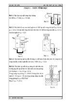
Figure 1
The Eurocodes
BS EN 1990, Eurocode:
Basis of structural design
Structural safety,
serviceability and durability
BS EN 1991, Eurocode 1:
Actions on structures
Actions on structures
BS EN 1992, Eurocode 2: Concrete
BS EN 1993, Eurocode 3: Steel
BS EN 1994, Eurocode 4: Composite
BS EN 1995, Eurocode 5: Timber
BS EN 1996, Eurocode 6: Masonry
BS EN 1999, Eurocode 9: Aluminium
BS EN 1997, Eurocode 7:
Geotechnical design
This Eurocode underpins all structural design irrespective of the
material of construction. It establishes principles and requirements for
safety, serviceability and durability of structures. (Note, the correct title
is Eurocode not Eurocode 0.) The Eurocode uses a statistical approach
to determine realistic values for actions that occur in combination with
each other.
Design and detailing
Geotechnical
and seismic
design
BS EN 1998, Eurocode 8:
Seismic design
Eurocode: Basis of
structural design
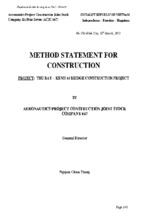
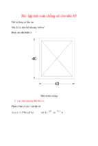
Figure 2
Typical Eurocode layout
There is no equivalent British Standard for Eurocode: Basis of structural
design and the corresponding information has traditionally been
replicated in each of the material Eurocodes. It also introduces new
definitions (see Glossary) and symbols (see Tables 2a and 2b), which
will be used throughout this publication to assist familiarity. Partial
factors for actions are given in this Eurocode, whilst partial factors for
materials are prescribed in their relevant Eurocode.
Representative values
A
B
A: National title page
B: National Foreword
C: CEN title page
C
D
D
D: Main text
E: Main Annex(es)
F: National Annex
D
D
E
F
Table 1
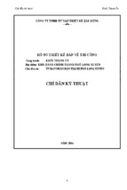
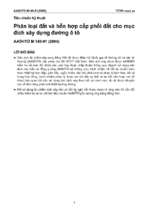
For each variable action there are four representative values. The
principal representative value is the characteristic value and this can be
determined statistically or, where there is insufficient data, a nominal
value may be used. The other representative values are combination,
frequent and quasi-permanent; these are obtained by applying to the
characteristic value the factors c 0 , c 1 and c 2 respectively (see Figure 3).
A semi-probabilistic method is used to derive the c factors, which vary
depending on the type of imposed load (see Table 3). Further information
on derivation of the c factors can be found in Appendix C of the Eurocode.
Concrete related Eurocodes and their equivalent current standards
Eurocode
Title
Superseded standards
BS EN 1990
Basis of structural design
BS 8110: Part 1 – section 2
BS EN 1991–1–1
Densities, self-weight and
imposed loads
BS 6399: Part 1 and BS 648
BS EN 1991–1–2
Actions on structures
exposed to fire
–
BS EN 1991–1–3
Snow loads
BS 6399: Part 2
BS EN 1991–1–4
Wind actions
BS 6399: Part 3
BS EN 1991–1–5
Thermal actions
–
BS EN 1991–1–6
Actions during execution
–
BS EN 1991–1–7
Accidental actions
–
BS EN 1991–2
Traffic loads on bridges
BD 37/88
BS EN 1991–3
Actions induced by cranes
and machinery
–
BS EN 1991–4
Silos and tanks
–
BS EN 1992–1–1
General rules for buildings
BS 8110: Parts 1, 2 and 3
BS EN 1992–1–2
Fire resistance of concrete
structures
BS 8110: Part 1,Table 3.2 and
BS 8110: Part 2, section 4
BS EN 1992–2
Bridges
BS 5400: Part 4
BS EN 1992–3
Liquid-retaining and
containment structures
BS 8007
BS EN 1997–1
Geotechnical design –
General rules
BS 6031, BS 8002, BS 8004,
BS 8006, BS 8008 & BS 8081
BS EN 1997–2
Geotechnical design – Ground BS 5930
investigation and testing
BS EN 1998
Design of structures for
–
earthquake resistance (6 parts)
2
The combination value (c 0 Qk) of an action is intended to take
account of the reduced probability of the simultaneous occurrence of
two or more variable actions. The frequent value ( c 1 Qk) is such that it
should be exceeded only for a short period of time and is used
primarily for the serviceability limit states (SLS) and also the accidental
ultimate limit state (ULS). The quasi-permanent value (c 2 Qk) may be
exceeded for a considerable period of time; alternatively it may be
considered as an average loading over time. It is used for the long-term
affects at the SLS and also accidental and seismic ULS.
Combinations of actions
In the Eurocodes the term ‘combination of actions’ is specifically used
for the definition of the magnitude of actions to be used when a limit
state is under the influence of different actions. It should not be
confused with ‘load cases’, which are concerned with the arrangement
of the variable actions to give the most unfavourable conditions and
are given in the material Eurocodes. The following process can be used
to determine the value of actions used for analysis:
1. Identify the design situation (e.g. persistent, transient, accidental).
2. Identify all realistic actions.
3. Determine the partial factors (see below) for each applicable
combination of actions.
4. Arrange the actions to produce the most critical conditions.
1. Introduction to Eurocodes
Where there is only one variable action (e.g. imposed load) in a
combination, the magnitude of the actions can be obtained by
multiplying them by the appropriate partial factors.
Where there is more than one variable action in a combination, it is
necessary to identify the leading action (Qk,1) and other accompanying
actions (Qk,i). The accompanying action is always taken as the
combination value.
Ultimate limit state
The ultimate limit states are divided into the following categories:
EQU Loss of equilibrium of the structure.
STR Internal failure or excessive deformation of the structure
or structural member.
GEO Failure due to excessive deformation of the ground.
FAT Fatigue failure of the structure or structural members.
The Eurocode gives different combinations for each of these ultimate
limit states. For the purpose of this publication only the STR ultimate
limit state will be considered.
For persistent and transient design situations under the STR limit
state, the Eurocode defines three possible combinations, which are given
in Expressions (6.10), (6.10a) and (6.10b) of the Eurocode (see Tables 4
and 5). The designer (for UK buildings) may use either (6.10) or the less
favourable of (6.10a) and (6.10b).
Table 2a
Selected symbols for Eurocode
Symbol
Gk
Definition
Characteristic value of permanent action
Qk
gG
Characteristic value of single variable action
gQ
Partial factor for variable action
c0
Factor for combination value of a variable action
c1
Factor for frequent value of a variable action
c2
Factor for quasi-permanent value of a variable action
j
Combination factor for permanent actions
Partial factor for permanent action
Table 2b
Selected subscripts
Subscript
Definition
A
Accidental situation
c
Concrete
d
Design
E
Effect of action
fi
Fire
k
Characteristic
R
Resistance
w
Shear reinforcement
y
Yield strength
Figure 3
Representative values of variable actions ⁵
Instantaneous value of Q
Characteristic value of QK
At first sight it appears that there is considerably more calculation
required to determine the appropriate load combination; however, with
experience the designer will be able to determine this by inspection.
Expression (6.10) is always equal to or more conservative than the less
favourable of Expressions (6.10a) and (6.10b). Expression (6.10b) will
normally apply when the permanent actions are not greater than 4.5
times the variable actions (except for storage loads (category E, Table 3)
where Expression (6.10a) always applies).
Combination value of c0 QK
Frequent value of c1 QK
Quasipermanent
value of c2 QK
Time
Therefore, for a typical concrete frame building, Expression (6.10b) will
give the most structurally economical combination of actions.
Table 3
Recommended values of c factors for buildings (from UK National Annex)
Action
For members supporting one variable action the combination
1.25 Gk + 1.5 Qk (derived from (Exp 6.10b))
can be used provided the permanent actions are not greater
than 4.5 times the variable actions (except for storage loads).
Serviceability limit state
There are three combinations of actions that can be used to check the
serviceability limit states (see Tables 6 and 7). Eurocode 2 indicates
which combination should be used for which phenomenon (e.g.
deflection is checked using the quasi-permanent combination). Care
should be taken not to confuse the SLS combinations of characteristic,
frequent and quasi-permanent, with the representative values that
have the same titles.
c0
c1
c2
Imposed loads in buildings (see BS EN 1991–1–1)
Category A: domestic, residential areas
0.7
0.5
0.3
Category B: office areas
0.7
0.5
0.3
Category C: congregation areas
0.7
0.7
0.6
Category D: shopping areas
0.7
0.7
0.6
Category E: storage areas
1.0
0.9
0.8
Category F: traffic area, vehicle weight < 30 kN
0.6
0.7
0.7
Category G: traffic area, 30 kN < vehicle weight < 160 kN 0.7
0.5
0.3
Category H: roofs*
0
0
0.7
Snow loads on buildings (see BS EN 1991–3)
For sites located at altitude H > 1000 m above sea level
0.7
0.5
0.2
For sites located at altitude H < 1000 m above sea level
Wind loads on buildings (see BS EN 1991–1–4)
0.5
0.5
0.2
0.2
0
0
Temperature (non-fire) in buildings (see BS EN 1991–1–5) 0.6
0.5
0
Key
*See also 1991–1–1: Clause 3.3.2
3
How to design concrete structures using Eurocode 2
Table 4
Design values of actions, ultimate limit state – persistent and transient design situations (table A1.2 (B) Eurocode)
Combination Expression reference
Permanent actions
Leading variable action
Unfavourable
Favourable
Exp. (6.10)
g G, j, sup Gk , j , sup
g G , j, inf G k , j , inf
Exp. (6.10a)
g G, j, sup Gk , j , sup
g G , j, inf G k , j , inf
Exp. (6.10b)
jg G, j, sup Gk , j , sup
g G , j, inf G k , j , inf
Accompanying variable actions
Main (if any)
g Q,1 Qk,1
Others
g Q,1 c 0 ,1 Q k,i
g Q,1 c 0 ,1 Qk,1
g Q,1 Qk,1
g Q,1 c 0 ,1 Q k,i
g Q,1 c 0 ,1 Q k,i
Note
1 Design for either Expression (6.10) or the less favourable of Expressions (6.10a) and (6.10b).
Table 5
Design values of actions, derived for UK design, ultimate limit state – persistent and transient design situations
Combination Expression reference
Permanent actions
Unfavourable
Leading variable action
Favourable
Accompanying variable actions
Main (if any)
Others
Combination of permanent and variable actions
Exp. (6.10)
1.35 Gk a
Exp. (6.10a)
1.35 Gk a
Exp. (6.10b)
0.925 d
1.5c Qk
1.0 Gk a
1.5 c 0,1b Qk
1.0 Gk a
x 1.35 Gk
a
1.0 Gk
a
1.5c
Qk
Combination of permanent, variable and accompanying variable actions
Exp. (6.10)
1.35 Gk a
1.0 Gk a
Exp. (6.10a)
1.35 Gk a
1.0 Gk a
Exp. (6.10b)
0.925 d x 1.35 Gk a
1.0 Gk a
1.5 c c 0,i b Q k,i
1.5c Qk,1
1.5 c 0,1b Qk
1.5 c c 0,i b Q k,i
1.5 c c 0,i b Q k,i
1.5c Qk,1
Key
a Where the variation in permanent action is not considered significant, Gk,j,sup and Gk,j,inf may be taken as Gk
c Where the accompanying load is favourable, g Q,i = 0
b The value of c 0 can be obtained from Table NA A1.1 of the UK National Annex (reproduced here as Table 3)
d The value of j in the UK National Annex is 0.925
Table 6
Design values of actions, serviceability limit states
Combination
Permanent actions
Variable actions
Example of use in Eurocode 2
Unfavourable
Favourable
Leading
Others
Characteristic
Gk,j,sup
Gk,j,inf
Qk,1
c 0 , i Qk,i
Frequent
Gk,j,sup
Gk,j,inf
c 1,1 Qk,1
c 2 , i Qk,i
Cracking – prestressed concrete
Quasi-permanent
Gk,j,sup
Gk,j,inf
c 2,1 Qk,1
c 2 , i Qk,i
Deflection
Notes
1 Where the variation in permanent action is not considered significant. Gk,j,sup and Gk,j,inf may be taken as Gk
2 For values of c 0, c 1 and c 2 refer to Table 3
Table 7
Example design combinations for deflection (quasi-permanent) derived for typical UK reinforced concrete design
Combination
Permanent actions
Variable action
Unfavourable
Leading
Gk a
0.3 b Q k,1
Shopping area
Gk
a
0.6b Q k,1
Storage
Gk a
0.8b Q k,1
Office
Key
a Where the variation in permanent action is not considered significant Gk,j,sup and Gk,j,inf may be taken as Gk
4
b Values of c 2 are taken from UK NA (see Table 3)
1. Introduction to Eurocodes
Eurocode 1
Eurocode 1 supersedes BS 6399: Loading for buildings6 and BS 648:
Schedule of weights of building materials7. It contains within its ten parts
(see Table 8) all the information required by the designer to assess the
individual actions on a structure. It is generally self-explanatory and it
is anticipated the actions to be used in the UK (as advised in the UK
National Annex) will typically be the same as those in the current
British Standards. The most notable exception is the bulk density of
reinforced concrete, which has been increased to 25 kN/m3. Currently
not all the parts of Eurocode 1 and their National Annexes are
available, in which case it is advised that the loads recommended in
the current British Standards are used.
Eurocode 2
There are four parts to Eurocode 2; Figure 4 indicates how they fit into
the Eurocode system, which includes other European standards.
Table 8
Eurocode 1, its parts and dates of publication
Reference
Publication date
Eurocode
National Annex
BS EN 1991–1–1
Densities,
self-weight and
imposed loads
July
2002
December
2005
BS EN 1991–1–2
Actions on
structures
exposed to fire
November
2002
Due
October
2006a
BS EN 1991–1–3
Snow loads
July
2003
December
2005
BS EN 1991–1–4
Wind actions
April
2005
Due
January
2007a
BS EN 1991–1–5
Thermal actions
March
2004
Due
December
2006a
BS EN 1991–1–6
Actions during
execution
December
2005
Due
June
2007a
BS EN 1991–1–7
Accidental actions
due to impact
and explosions
September
2006
Due
October
2007a
BS EN 1991–2
Traffic loads
on bridges
October
2003
Due
December
2006a
BS EN 1991–3
Actions induced
by cranes
and machinery
September
2006
Due
January
2007a
BS EN 1991–4
Actions in silos
and tanks
June
2006
Due
June
2007a
Part 1–1
Eurocode 2, Part 1–1: General rules and rules for buildings9 is the
principal part which is referenced by the three other parts. For the UK
designer there are a number of differences between Eurocode 2 and
BS 8110, which will initially make the new Eurocode seem unfamiliar.
The key differences are listed below to assist in the familiarisation process.
1. Eurocode 2 is generally laid out to give advice on the basis of
phenomena (e.g. bending, shear etc) rather than by member
types as in BS 8110 (e.g. beams, slabs, columns etc).
2. Design is based on characteristic cylinder strengths not cube
strengths.
3. The Eurocode does not provide derived formulae (e.g. for bending,
only the details of the stress block are expressed). This is the
traditional European approach, where the application of a Eurocode
is expected to be provided in a textbook or similar publication.
The Eurocodes allow for this type of detail to be provided in
‘Non-contradictory complementary information’ (NCCI) (See
Glossary).
4. Units for stress are mega pascals, MPa (1 MPa = 1 N/mm2).
5. Eurocode 2 uses a comma for a decimal point. It is expected that
UK designers will continue to use a decimal point. Therefore to
avoid confusion, the comma should not be used for separating
multiples of a thousand.
6. One thousandth is represented by ‰.
7. The partial factor for steel reinforcement is 1.15. However, the
characteristic yield strength of steel that meets the requirements
of BS 4449 will be 500 MPa; so overall the effect is negligible.
8. Eurocode 2 is applicable for ribbed reinforcement with characteristic
yield strengths of 400 to 600 MPa. There is no guidance on plain
bar or mild steel reinforcement in the Eurocode, but guidance is
given in the background paper to the UK National Annex10.
9. The effects of geometric imperfection (‘notional horizontal loads’)
are considered in addition to lateral loads.
Title
Key
a Planned publication date (correct at time of publication) Source: BSI8
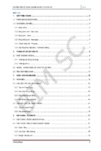
Figure 4
Relationship between Eurocode 2 and other Eurocodes
BS EN 1997
EUROCODE 7
Geotechnical
design
BS EN 1990
EUROCODE
Basis of structural
design
BS EN 1998
EUROCODE 8
Seismic
design
BS EN 206
Specifying
concrete
BS EN 1991
EUROCODE 1
Actions on
structures
BS EN 10080
Reinforcing
steels
BS 8500
Specifying
concrete
BS EN 1992
EUROCODE 2
Design of concrete
structures
BS 4449
Reinforcing
steels
Part 1–1: General
rules for structures
BS EN 13670
Execution of
structures
Part 1–2: Structural
fire design
BS EN 13369
Precast
concrete
BS EN 1992
EUROCODE 2
Part 2:
Bridges
BS EN 1992 Part 3:
EUROCODE 2
Liquid-retaining
structures
Precast
concrete
product
standards
5
How to design concrete structures using Eurocode 2
10. Minimum concrete cover is related to bond strength, durability
and fire resistance. In addition to the minimum cover an
allowance for deviations due to variations in execution
(construction) should be included. Eurocode 2 recommends
that, for concrete cast against formwork, this is taken as 10 mm,
unless the construction is subject to a quality assurance system
in which case it could be reduced to 5 mm or even 0 mm where
non-conforming members are rejected (e.g. in a precast yard).
It is recommended that the nominal cover is stated on the
drawings and construction tolerances are given in the
specification.
11. Higher strengths of concrete are covered by Eurocode 2, up to
class C90/105. However, because the characteristics of higher
strength concrete are different, some Expressions in the Eurocode
are adjusted for classes above C50/60.
12. The ‘variable strut inclination’ method is used in Eurocode 2 for
the assessment of the shear capacity of a section. In practice,
design values for actual structures can be compared with
tabulated values. Further advice can be found in Chapter 4,
originally published as Beams11.
13. The punching shear checks are carried out at 2d from the face of
the column and for a rectangular column, the perimeter is
rounded at the corners.
14. Serviceability checks can still be carried out using ‘deemed to
satisfy’ span to effective depth rules similar to BS 8110. However,
if a more detailed check is required, Eurocode 2 guidance varies
from the rules in BS 8110 Part 2.
15. The rules for determining the anchorage and lap lengths are more
complex than the simple tables in BS 8110. Eurocode 2 considers
the effects of, amongst other things, the position of bars during
concreting, the shape of the bar and cover.
Part 1–2
Eurocode 2, Part 1–2: Structural fire design12, gives guidance on design for
fire resistance of concrete structures. Although much of the Eurocode
is devoted to fire engineering methods, the design for fire resistance
may still be carried out by referring to tables for minimum cover and
dimensions for various elements. These are given in section 5 of Part
1–2. Further advice on using the tabular method is given in Chapter 2,
originally published as Getting started 13.
Eurocode 7
Eurocode 7: Geotechnical design17 is in two parts and gives guidance on
geotechnical design, ground investigation and testing. It has a broad
scope and includes the geotechnical design of spread foundations, piled
foundations, retaining walls, deep basements and embankments. Like
all the Eurocodes it is based on limit state design principles, which is
a significant variation for most geotechnical design. Further guidance
related to simple foundations is given in Chapter 6, originally
ppublished as Foundations18.
Eurocode 8
Eurocode 8: Design of structures for earthquake resistance19 is divided into
six parts and gives guidance on all aspects of design for earthquake
resistance and covers guidance for the various structural materials for
all types of structures. It also includes guidance for strengthening and
repair of buildings. In areas of low seismicity it is anticipated that detailing
structures to Eurocode 2 will ensure compliance with Eurocode 8.
Related Standards
BS 8500/BS EN 206
BS 8500: Concrete – Complementary British Standard to BS EN 206–120
replaced BS 5328 in December 2003 and designers should currently
be using this to specify concrete. Further guidance can found in
Chapter 11, originally published as How to use BS 8500 with BS 811021.
BS 4449/BS EN 10080
BS 4449: Specification for carbon steel bars for the reinforcement of
concrete22 has been revised ready for implementation in January 2006.
It is a complementary standard to BS EN 10080 Steel for the
reinforcement of concrete23 and Normative Annex C of Eurocode 2. The
most significant changes are that steel characteristic yield will change
to 500 MPa. There are three classes of reinforcement, A, B and C, which
indicate increasing ductility. Class A is not suitable for use where
redistribution of 20% and above has been assumed in the design.
BS EN 13670
Part 2
Eurocode 2, Part 2: Bridges14 applies the general rules given in Part 1–1
to the design of concrete bridges. As a consequence both Part 1–1 and
Part 2 will be required to carry out a design of a reinforced concrete
bridge.
Part 3
Eurocode 2, Part 3: Liquid-retaining and containment structures15 applies
the general rules given in Part 1–1 to the liquid-retaining structures
and supersedes BS 800716.
6
BS 8110 Part 1 sections 6 and 7 specify the workmanship for concrete
construction. There is no equivalent guidance in Eurocode 2, and it is
intended that execution (construction) will be covered in a new
standard BS EN 13670 Execution of concrete structures24. This is still in
preparation and is not expected to be ready for publication until 2008
at the earliest. In the intervening period the draft background paper to
the UK National Annex of Eurocode 2, Part 1-110 recommends that
designers use the National structural concrete specification for building
construction25, which refers to BS 8110 for workmanship.
1. Introduction to Eurocodes
Glossary of Eurocode terminology
Term
Definition
Principles
Clauses that are general statements, definitions, requirements and analytical models for which no
alternative is permitted. They are identified by (P) after the clause number.
Application Rules
These are generally recognised rules, which comply with the principles and satisfy their requirements.
Nationally Determined Parameter (NDP)
Eurocodes may be used to satisfy national Building Regulations, which themselves will not be
harmonized. NDPs are therefore used to allow a country to set its own levels of safety. NDPs also allow
certain other parameters (generally influenced by climate, geography and geology) to be left open for
selection nationally: NDPs are advised in the National Annex.
National Annex (NA)
A National Annex accompanies each Eurocode and it contains a) the values of NDPs b) the national
decision regarding the use of Informative Annexes and c) references to NCCIs
Normative
The term used for the text of Standards that forms the core requirements. Compliance with Eurocodes
will generally be judged against the normative requirements.
Informative
A term used only in relation to annexes, which seek to inform rather than require.
NCCI
Non-contradictory complementary information. References in a National Annex which contains further
information or guidance which does not contradict the Eurocode.
Characteristic value
A value that may be derived statistically with a probability of not being exceeded during a reference
period. The value corresponds to a specified fractile for a particular property of material or product. The
characteristic values are denoted by subscript ‘k’ (e.g. Qk etc). It is the principal representative value
from which other representative values may be derived.
Representative value
Value used for verification of a limit state. It may be the characteristic value or an accompanying value,
e.g. combination, frequent or quasi-permanent.
Design values
These refer to representative values modified by partial factors. They are denoted by subscript ‘d’
(e.g. f cd = f ck /g c ; Qd = g Q Qk).
Action (F)
Set of forces, deformations or accelerations acting on the structure.
Combination of actions
Set of design values used for the verification of the structural reliability for a limit state under the
simultaneous influence of different and statistically independent actions.
Fixed action
Action that has a fixed distribution and position over the structure or structural member.
Free action
Action that may have various spatial distributions over the structure.
Permanent actions (G)
Actions that are likely to act throughout the life of the structure and whose variation in magnitude
with time is negligible (e.g. permanent loads).
Variable actions (Q)
Actions whose magnitude will vary with time (e.g. wind loads).
Effect of action (E)
Deformation or internal force caused by an action.
Accidental action (A)
Action, usually of short duration but of significant magnitude, that is unlikely to occur on a given
structure during the design working life.
Accompanying action
An action in a combination that is not the leading variable action.
Transient design situation
Design situation that is relevant during a period much shorter than the design working life of the structure.
Persistent design situation
Design situation that is relevant during a period of the same order as the design working life of the structure.
Accidental design situation
Design situation involving exceptional conditions of the structure.
Irreversible serviceability limit state
Serviceability limit state where some consequences of actions will remain when the actions are removed.
Reversible serviceability limit state
Serviceability limit state where no consequences of actions will remain when the actions are removed.
Execution
Construction of the works.
7
1. Introduction to Eurocodes
References
1 BRITISH STANDARDS INSTITUTION. BS EN 1992, Eurocode 2: Design of concrete structures. BSI (4 parts).
2 BRITISH STANDARDS INSTITUTION. BS EN 1990, Eurocode: Basis of structural design. BSI, 2002.
3 BRITISH STANDARDS INSTITUTION. BS EN 1991, Eurocode 1: Actions on structures. BSI (10 parts).
4 BRITISH STANDARDS INSTITUTION. BS 8110: The structural use of concrete. BSI (3 parts).
5 GULVANESSIAN, H, CALGARO, J A & HOLICÝ, M T. Designers’ guide to EN 1990. Thomas Telford, 2002.
6 BRITISH STANDARDS INSTITUTION. BS 6399: Loading for buildings. BSI (3 parts).
7 BRITISH STANDARDS INSTITUTION. BS 648: Schedule of weights of building materials. BSI, 1964.
8 BRITISH STANDARDS INSTITUTION. Web page: www.bsi-global.com/Eurocodes/Progress/index.xalter. BSI.
9 BRITISH STANDARDS INSTITUTION. BS EN 1992–1–1, Eurocode 2: Design of concrete structures. General rules and rules for buildings. BSI, 2004.
10 BRITISH STANDARD INSTITUTION. PD 6687. Background paper to the UK National Annex to BS EN 1992–1–1. BSI, 2006.
11 MOSS, R M & BROOKER, O. How to design concrete structures using Eurocode 2: Beams (TCC/03/19). The Concrete Centre, 2006.
12 BRITISH STANDARDS INSTITUTION. BS EN 1992–1–2, Eurocode 2: Design of concrete structures. Structural fire design. BSI, 2004.
13 BROOKER, O. How to design concrete structures using Eurocode 2: Getting started (TCC/03/17). The Concrete Centre, 2005.
14 BRITISH STANDARDS INSTITUTION. BS EN 1992–2, Eurocode 2: Design of concrete structures. Bridges. BSI, 2005.
15 BRITISH STANDARDS INSTITUTION. BS EN 1992–3, Eurocode 2: Design of concrete structures. Liquid-retaining and containment structures.
BSI, due 2006.
16 BRITISH STANDARDS INSTITUTION. BS 8007: Code of practice for design of concrete structures for retaining aqueous liquids. BSI, 1987.
17 BRITISH STANDARDS INSTITUTION. BS EN 1997, Eurocode 7: Geotechnical design. BSI (2 parts).
18 WEBSTER, R & BROOKER, O. How to design concrete structures using Eurocode 2: Foundations (TCC/03/21). The Concrete Centre, 2006.
19 BRITISH STANDARDS INSTITUTION. BS EN 1998, Eurocode 8: Design of structures for earthquake resistance. BSI (6 parts).
20 BRITISH STANDARDS INSTITUTION. BS 8500: Concrete – Complementary British Standard to BS EN 206–1, 2002 (2 parts).
21 HARRISON, T A & BROOKER, O. How to use BS 8500 with BS 8110 (TCC/03/11). The Concrete Centre, 2005.
22 BRITISH STANDARDS INSTITUTION. BS 4449: Specification for carbon steel bars for the reinforcement of concrete. BSI, 2005.
23 BRITISH STANDARDS INSTITUTION. BS EN 10080: Steel for the reinforcement of concrete – Weldable reinforcing steel – General. BSI, 2005.
24 BRITISH STANDARDS INSTITUTION. EN 13670: Execution of concrete structures – Part 1: Common. BSI, due 2008.
25 THE CONCRETE SOCIETY. CS 152: National structural concrete specification for building construction, third edition. The Society, 2004.
8
How to design concrete structures using Eurocode 2
2. Getting started
O Brooker BEng, CEng, MICE, MIStructE
The design process
This chapter is intended to assist the designer determine all the design
information required prior to embarking on detailed element design. It
covers design life, actions on structures, load arrangements, combinations
of actions, method of analysis, material properties, stability and
imperfections, minimum concrete cover and maximum crack widths.
The process of designing elements will not be revolutionised as a result
of using Eurocode 21, although much of the detail may change – as
described in subsequent chapters.
Similarly, the process of detailing will not vary significantly from current
practice. Guidance can be found in Chapter 10 or in Standard method of
detailing 2. With regard to specification, advice can be found in Chapter 1,
originally published as Introduction to Eurocodes3. Concept designs
prepared assuming that detailed design would be to BS 8110 may be
continued through to detailed design using Eurocode 2.
In the long-term it is anticipated that Eurocode 2 will lead to more
economic structures.
Design life
The design life for a structure is given in Eurocode: Basis of structural
design 4. The UK National Annex (NA) to Eurocode presents UK values
for design life; these are given in Table 1 (overleaf). These should be used
to determine the durability requirements for the design of reinforced
concrete structures.
Actions on structures
Eurocode 1: Actions on structures5 consists of 10 parts giving details of
a wide variety of actions. Further information on the individual codes
can be found in Chapter 1. Eurocode 1, Part 1–1: General actions –
Densities, self-weight, imposed loads for buildings6 gives the densities and
self-weights of building materials (see Table 2 overleaf).
The key change to current practice is that the bulk density of reinforced
concrete has been increased to 25 kN/m3. The draft National Annex to
this Eurocode gives the imposed loads for UK buildings and a selection is
How to design concrete structures using Eurocode 2
Table 1
Indicative design working life (from UK National Annex to Eurocode)
Design life (years)
Examples
10
Temporary structures
10–30
Replaceable structural parts
15–25
Agricultural and similar structures
50
120
Buildings and other common structures
Monumental buildings, bridges and other civil
engineering structures
Table 2
Selected bulk density of materials (from Eurocode 1, Part 1–1)
Material
Bulk density (kN/m3)
Normal weight concrete
24.0
Reinforced normal weight concrete
25.0
Wet normal weight reinforced concrete
26.0
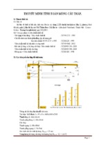
Figure 1
Alternate spans loaded
reproduced in Table 3. It should be noted that there is no advice given
for plant rooms.
At the time of writing not all the parts of Eurocode 1 and their National
Annexes are available; it is advised that existing standards are considered
for use where European standards have not yet been issued.
Load arrangements
The term load arrangements refers to the arranging of variable actions
(e.g. imposed and wind loads) to give the most onerous forces in a
member or structure and are given in Eurocode 2 and its UK NA.
For building structures, the UK NA to Eurocode 2, Part 1–1 allows any
of the following sets of load arrangements to be used for both the
ultimate limit state and serviceability limit state:
Load set 1. Alternate or adjacent spans loaded
The design values should be obtained from the more critical of:
■ Alternate spans carrying the design variable and permanent loads
with other spans loaded with only the design permanent load (see
Figure 1). The value of gG should be the same throughout.
■ Any two adjacent spans carrying the design variable and
permanent loads with other spans loaded with only the design
permanent load (see Figure 2). The value of gG should be the
same throughout.
Load set 2. All or alternate spans loaded
Figure 2
Adjacent spans loaded
The design values should be obtained from the more critical of:
■ All spans carrying the design variable and permanent loads
(see Figure 3).
■ Alternate spans carrying the design variable and permanent loads
with other spans loaded with only the design permanent load (see
Figure 1). The value of gG should be the same throughout.
Generally, load set 2 will be used for beams and slabs in the UK as it
requires three load arrangements to be considered, while load set 1
will often require more than three arrangements to be assessed.
Alternatively, the UK NA makes the following provision for slabs.
Load set 3. Simplified arrangements for slabs
Figure 3
All spans loaded
2
10
The load arrangements can be simplified for slabs where it is only
necessary to consider the all spans loaded arrangement (see Figure 3),
provided the following conditions are met:
■ In a one-way spanning slab the area of each bay exceeds 30 m2
(a bay means a strip across the full width of a structure bounded
on the other sides by lines of support).
■ The ratio of the variable actions (Qk) to the permanent actions (Gk)
does not exceed 1.25.
■ The magnitude of the variable actions excluding partitions does not
exceed 5 kN/m2.
2. Getting started
Combination of actions
The term combination of actions refers to the value of actions to be
used when a limit state is under the influence of different actions.
The numerical values of the partial factors for the ULS combination can
be obtained by referring to Eurocode: Basis of structural design or to
Chapter 1.
.(
For members supporting one variable action the ULS combination
1.25 Gk + 1.5 Qk (derived from Exp. (6.10b), Eurocode)
can be used provided the permanent actions are not greater than
4.5 times the variable actions (except for storage loads).
There are three SLS combinations of actions – characteristic, frequent
and quasi-permanent. The numerical values are given in Eurocode: Basis
of structural design.
Material properties
Concrete
In Eurocode 2 the design of reinforced concrete is based on the
characteristic cylinder strength rather than cube strength and should
be specified according to BS 8500: Concrete – complementary British
Standard to BS EN 206–17 (e.g. for class C28/35 concrete the cylinder
strength is 28 MPa, whereas the cube strength is 35 MPa). Typical
concrete properties are given in Table 4.
Concrete up to class C90/105 can be designed using Eurocode 2.
For classes above C50/60, however, there are additional rules and
variations. For this reason, the design of these higher classes is not
considered in this publication.
It should be noted that designated concretes (e.g. RC30) still refer
to the cube strength.
Reinforcing steel
Eurocode 2 can be used with reinforcement of characteristic
strengths ranging from 400 to 600 MPa. The properties of steel
reinforcement in the UK for use with Eurocode 2 are given in
BS 4449 (2005): Specification for carbon steel bars for the
reinforcement of concrete 8 and are summarised in Table 5 (on page 4).
A characteristic yield strength of 500 MPa has been adopted by the
UK reinforcement industry. There are three classes of reinforcement,
A, B and C, which provide increasing ductility. Class A is not suitable
where redistribution of 20% and above has been assumed in the
design. There is no provision for the use of plain bar or mild steel
reinforcement, but guidance is given in the background paper to the
National Annex9.
Table 3
Selected imposed loads for buildings (from draft UK National Annex to Eurocode 1, Part 1–1)
Category
qk (kN/m2)
Example use
Qk (kN)
A1
All uses within self-contained dwelling units
1.5
2.0
A2
Bedrooms and dormitories
1.5
2.0
A3
Bedrooms in hotels and motels, hospital wards and toilets
2.0
2.0
A5
Balconies in single family dwelling units
2.5
2.0
A7
Balconies in hotels and motels
4.0 min.
2.0 at outer edge
B1
Offices for general use
2.5
2.7
C5
Assembly area without fixed seating, concert halls, bars, places of worship
5.0
3.6
D1/2
Shopping areas
4.0
3.6
E12
General storage
2.4 per m height
7.0
E17
Dense mobile stacking in warehouses
4.8 per m height (min. 15.0)
7.0
F
Gross vehicle weight ≤ 30kN
2.5
10.0
Table 4
Selected concrete properties based on Table 3.1 of Eurocode 2, Part 1–1
Symbol
Description
Properties
fck (MPa)
Characteristic cylinder strength
12
16
20
25
30
35
40
45
50
28a
32a
fck,cube (MPa)
Characteristic cube strength
15
20
25
30
37
45
50
55
60
35
40
fctm (MPa)
Mean tensile strength
1.6
1.9
2.2
2.6
2.9
3.2
3.5
3.8
4.1
2.8
3.0
Ecm b (GPa)
Secant modulus of elasticity
27
29
30
31
33
34
35
36
37
32
34
Key
a Concrete class not cited in Table 3.1, Eurocode 2, Part 1–1
b Mean secant modulus of elasticity at 28 days for concrete with quartzite aggregates. For concretes with other aggregates refer to Cl 3.1.3 (2)
3
11
How to design concrete structures using Eurocode 2
Structural analysis
Table 5
Characteristic tensile properties of reinforcement
Class (BS 4449) and designation (BS 8666)
A
B
C
Characteristic yield strength fyk or f 0.2k (MPa)
500
500
500
Minimum value of k = ( ft /fy ) k
≥ 1.05 ≥ 1.08 ≥ 1.15 < 1.35
Characteristic strain at maximum force e uk (%)
≥ 2.5
≥ 5.0
≥ 7.5
Notes
1 Table derived from BS EN 1992–1–1 Annex C, BS 4449: 2005 and BS EN 1008010 .
2 The nomenclature used in BS 4449: 2005 differs from that used in BS EN 1992–1–1
Annex C and used here.
3 In accordance with BS 8666, class H may be specified, in which case class A, B or C
may be supplied.
Table 6
Bending moment and shear co-efficients for beams
Moment
Shear
Outer support
25% of span moment
0.45 (G + Q)
Near middle of end span
0.090 Gl + 0.100 Ql
At first interior support
– 0.094 (G + Q) l
At middle of interior spans
At interior supports
0.63 (G + Q)a
0.066 Gl + 0.086 Ql
– 0.075 (G + Q) l
0.50 (G + Q)
Key
a 0.55 (G + Q) may be used adjacent to the interior span.
Notes
1 Redistribution of support moments by 15% has been included.
2 Applicable to 3 or more spans only and where Qk ≤ G k.
3 Minimum span ≥ 0.85 longest span.
4 l is the effective length, G is the total of the ULS permanent actions, Q is the total
of the ULS variable actions.
Table 7
Exposure classes
Class
Description
No risk of corrosion or attack
X0
For concrete without reinforcement or embedded metal where there
is no significant freeze/thaw, abrasion or chemical attack.
Corrosion induced by carbonation
XC1
Dry or permanently wet
XC2
Wet, rarely dry
XC3/4
Moderate humidity or cyclic wet and dry
Corrosion induced by chlorides other than from seawater
XD1
Moderate humidity
XD2
Wet, rarely dry
XD3
Cyclic wet and dry
Corrosion induced by chlorides from seawater
The primary purpose of structural analysis in building structures is to
establish the distribution of internal forces and moments over the
whole or part of a structure and to identify the critical design
conditions at all sections. The geometry is commonly idealised by
considering the structure to be made up of linear elements and plane
two-dimensional elements.
The type of analysis should be appropriate to the problem being
considered. The following may be used: linear elastic analysis, linear
elastic analysis with limited redistribution, and plastic analysis. Linear
elastic analysis may be carried out assuming cross sections are
uncracked (i.e. concrete section properties); using linear stress-strain
relationships, and assuming mean values of elastic modulus.
For the ultimate limit state only, the moments derived from elastic
analysis may be redistributed (up to a maximum of 30%) provided
that the resulting distribution of moments remains in equilibrium with
the applied loads and subject to certain limits and design criteria (e.g.
limitations of depth to neutral axis).
Regardless of the method of analysis used, the following principles apply:
■ Where a beam or slab is monolithic with its supports, the critical
design hogging moment may be taken as that at the face of the
support, but should not be taken as less than 0.65 times the full
fixed end moment.
■ Where a beam or slab is continuous over a support that may be
considered not to provide rotational restraint, the moment
calculated at the centre line of the support may be reduced by
(FEd,sup t/8), where FEd,sup is the support reaction and t is the breadth
of the support.
■ For the design of columns the elastic moments from the frame
action should be used without any redistribution.
Bending moment and shear force co-efficients for beams are given in
Table 6; these are suitable where spans are of similar length and the
other notes to the table are observed.
Minimum concrete cover
XS1
Exposed to airborne salt but not in direct contact with sea water
The nominal cover can be assessed as follows:
XS2
Permanently submerged
cnom = cmin + D cdev
XS3
Tidal, splash and spray zones
Freeze/thaw with or without de-icing agents
XF1
Moderate water saturation without de-icing agent
XF2
Moderate water saturation with de-icing agent
XF3
High water saturation without de-icing agent
XF4
High water saturation with de-icing agent or sea water
Chemical attack (ACEC classes)
Refer to BS 8500–1 and Special Digest 111
4
12
Exp. (4.1)
Where cmin should be set to satisfy the requirements below:
■ safe transmission of bond forces
■ durability
■ fire resistance
and D cdev is an allowance which should be made in the design for
deviations from the minimum cover. It should be taken as 10 mm,
unless fabrication (i.e. construction) is subjected to a quality assurance
system, in which case it is permitted to reduce D cdev to 5 mm.
2. Getting started
Figure 4
Sections through structural members, showing nominal axis distance, a
National Annex (Table 4.3 (N) (BS)) gives durability requirements that
comply with BS 8500, but which significantly modify the approach
taken in Eurocode 2. To determine the minimum cover for durability
(and also the strength class and minimum water cement ratio) either
the UK National Annex or BS 8500 can be used.
The various exposure classes from BS 8500 are given in Table 7. Selected
recommendations are given in Table 8 (on page 6) for the concrete
strength, minimum cement ratio, minimum concrete cover and maximum
cement content for various elements in a structure based on the exposure
of that element. This is taken from Chapter 11, originally published as
How to use BS 8500 with BS 811013.
Table 9
Minimum column dimensions and axis distances for columns with
rectangular or circular section – method A
Standard fire
resistance
Minimum dimensions (mm)
Column width ( bmin)/axis distance (a) of the main bars
Column exposed on more
than one side ( m f i = 0.7)
Exposed on one side
( m f i = 0.7)
R 60
250/46
350/40
155/25
R 120
350/57*
450/51*
175/35
R 240
†
295/70
Notes
1 Refer to BS EN 1992–1–2 for design limitations.
2 m fi is the ratio of the design axial load under fire conditions to the design resistance
of the column at normal temperature conditions. Conservatively m fi may be taken
as 0.7
* Minimum 8 bars
† Method B indicates 600/70 for R 240 and m fi = 0.7 and may be used.
See EN 1992–1–2 Table 5.2b
Minimum cover for bond
The minimum cover to ensure adequate bond should not be less than
the bar diameter, or equivalent bar diameter for bundled bars, unless
the aggregate size is over 32 mm.
Minimum cover for durability
The recommendations for durability in Eurocode 2 are based on
BS EN 206–112. In the UK the requirements of BS EN 206 –1 are
applied through the complementary standard BS 8500. The UK
Design for fire resistance
Eurocode 2 Part 1–2: Structural fire design14, gives several methods
for determining the fire resistance of concrete elements; further
guidance can be obtained from specialist literature. Design for
fire resistance may still be carried out by referring to tables to
determine the minimum cover and dimensions for various elements,
as set out below.
Rather than giving the minimum cover, the tabular method is based
on nominal axis distance, a (see Figure 4). This is the distance from the
centre of the main reinforcing bar to the surface of the member. It is
a nominal (not minimum) dimension. The designer should ensure that
a ≥ cnom + f link + f bar /2.
There are three standard fire exposure conditions that may be satisfied:
R Mechanical resistance for load bearing
E Integrity of separation
I Insulation
Tables 9 and 10 give the minimum dimensions for columns and slabs
to meet the above conditions. The tables offer more flexibility than
BS 8110 in that there are options available to the designer e.g. section
sizes can be reduced by increasing the axis distance. Further information
is given in Eurocode 2 and subsequent chapters, including design
limitations and data for walls and beams.
Table 10
Minimum dimensions and axis distances for reinforced concrete slabs
Standard
fire
resistance
REI 60
REI 120
REI 240
hs
a
hs
a
hs
a
=
=
=
=
=
=
Minimum dimensions (mm)
One-way
Two-way spanning slab
Flat slab
spanning slab l y /l x ≤ 1.5
1.5 < l y /l x ≤ 2
Ribs in a two-way spanning ribbed slab
(bmin is the width of the rib)
80
20
120
40
175
65
bmin =
a=
bmin =
a=
bmin =
a=
80
10
120
20
175
40
80
15
120
25
175
50
180
15
200
35
200
50
100
25
160
45
450
70
120
15
190
40
700
60
≥200
10
≥300
30
–––
Notes
1 Refer to BS EN 1992–1–2 for design limitations.
2 a is the axis distance (see Figure 4).
3 h s is the slab thickness, including any non-combustible flooring.
5
13
How to design concrete structures using Eurocode 2
Table 8
Selected a recommendations for normal-weight reinforced concrete quality for combined exposure classes and cover to reinforcement for at least a
50-year intended working life and 20 mm maximum aggregate size
Cement/
Strength classc, maximum w/c ratio, minimum cement or combination
combination content (kg/m3), and equivalent designated concrete (where applicable)
designationsb
Exposure conditions
Typical example
Nominal cover to reinforcementd
Primary Secondary
15 + D c dev 20 + D c dev 25 + D c dev 30 + D c dev 35 + D c dev 40 + D c dev 45 + D c dev 50 + D c dev
X0
___
All
Recommended that this exposure is not applied to reinforced concrete
Internal elements
(except humid
locations)
XC1
___
All
C20/25,
0.70, 240 or
RC20/25
<<<
<<<
<<<
<<<
<<<
<<<
<<<
Buried concrete
in AC-1 ground
conditions e
XC2
All
___
___
C25/30,
0.65, 260 or
RC25/30
<<<
<<<
<<<
<<<
<<<
All except IVB
___
C40/50,
C30/37,
C28/35,
C25/30,
0.45, 340 or 0.55, 300
0.60, 280 or 0.65, 260 or
RC40/50
or RC30/37 RC28/35
RC25/30
<<<
<<<
<<<
XF1
All except IVB
___
C40/50,
C30/37,
C28/35,
0.45, 340 or 0.55, 300
0.60, 280 or
RC40/50
or RC30/37 RC28/35
<<<
<<<
<<<
<<<
XF3
All except IVB
___
C40/50,0.45,
340 g or
RC40/50XFg
<<<
<<<
<<<
<<<
<<<
XF3 (air
entrained)
All except IVB
___
___
C32/40,
0.55, 300
plus air g,h
C28/35,
0.60, 280
plus air g,h
or PAV2
C25/30,
0.60, 280
plus air g, h, j
or PAV1
<<<
<<<
<<<
All
___
___
C40/50,
0.45, 360
C32/40,
0.55, 320
C28/35,
0.60, 300
<<<
<<<
<<<
IIB-V, IIIA
___
___
___
___
___
C35/45,
0.40, 380
C32/40,
0.45, 360
C28/35,
0.50, 340
CEM I, IIA,
IIB-S, SRPC
___
___
___
___
___
See
BS 8500
C40/50,
0.40, 380
C35/45,
0.45, 360
IIIB, IVB-V
___
___
___
___
___
C32/40,
0.40, 380
C28/35,
0.45, 360
C25/30,
0.50, 340
IIB-V, IIIA
___
___
___
___
___
C35/45,
0.40, 380
C32/40,
0.45, 360
C32/40,
0.50, 340
CEM I, IIA,
IIB-S, SRPC
___
___
___
___
___
See
BS 8500
C40/50,
0.40, 380
C35/45,
0.45, 360
IIIB, IVB-V
___
___
___
___
___
C32/40,
0.40, 380
C32/40
0.45, 360
C32/40,
0.50, 340
XF4
CEM I, IIA,
IIB-S, SRPC
___
___
___
___
___
See
BS 8500
C40/50,
0.40, 380 g
<<<
XF4 (air
entrained)
IIB-V, IIIA, IIIB
___
___
___
___
___
C28/35,
C28/35
C28/35,
0.40, 380g, h 0.45, 360g, h 0.50, 340g, h
CEM I, IIA,
IIB-S, SRPC
___
___
___
See
BS 8500
C35/45,
0.45, 360
C32/40,
0.50, 340
<<<
<<<
IIB-V, IIIA
___
___
___
See
BS 8500
C32/40,
0.45, 360
C28/35,
0.50, 340
C25/30,
0.55, 320
<<<
IIIB
___
___
___
C32/40,
0.40, 380
C25/30,
0.50, 340
C25/30,
0.50, 340
C25/30,
0.55, 320
<<<
CEM I, IIA,
IIB-S, SRPC
___
___
___
See
BS 8500
C40/50,
0.45, 360 g
<<<
<<<
<<<
Internal mass
concrete
Vertical surface
protected from
direct rainfall
Exposed vertical
surfaces
___
XC3
&
XC4
Exposed horizontal
surfaces
Elements subject
to airborne
chlorides
XD1f
Car park decks and
areas subject to
de-icing spray
Vertical elements
subject to de-icing
spray and freezing
Exposed horizontal
surfaces near coast
___
___
XD3f
XF2
Car park decks,
ramps and external
areas subject to
freezing and
de-icing salts
Exposed vertical
surfaces near coast
AC-1
XF1
XS1f
XF4
Key
a This table comprises a selection of common exposure class combinations.
Requirements for other sets of exposure classes, e.g. XD2, XS2 and XS3 should
be derived from BS 8500-1: 2002, Annex A.
b See BS 8500-2,Table 1. (CEM I is Portland cement, IIA to IVB are cement combinations.)
c For prestressed concrete the minimum strength class should be C28/35.
6
14
d
e
f
g
h
j
<<<
D c dev is an allowance for deviations.
For sections less than 140 mm thick refer to BS 8500.
Also adequate for exposure class XC3/4.
Freeze/thaw resisting aggregates should be specified.
Air entrained concrete is required.
This option may not be suitable for areas subject to
severe abrasion.
___
Not recommended
<<<
Indicates that concrete
quality in cell to the left
should not be reduced
2. Getting started
Stability and imperfections
Crack control
The effects of geometric imperfections should be considered in
combination with the effects of wind loads (i.e. not as an alternative
load combination). For global analysis, the imperfections may be
represented by an inclination y i .
Crack widths should be limited to ensure appearance and durability
are satisfactory. In the absence of specific durability requirements
(e.g. water tightness) the crack widths may be limited to 0.3 mm in
all exposure classes under the quasi-permanent combination. In the
absence of requirements for appearance, this limit may be relaxed (to
say 0.4 mm) for exposure classes X0 and XC1 (refer to Table 7). The
theoretical size of the crack can be calculated using the expressions
given in Cl 7.3.4 from Eurocode 2–1–1 or from the ‘deemed to satisfy’
requirements that can be obtained from Table 11, which is based on
tables 7.2N and 7.3N of the Eurocode. The limits apply to either the
bar size or the bar spacing, not both.
y i = (1/200) x a h x a m
where
a h = (2/Rl), to be taken as not less than 2/3 nor greater than 1.0
a m = [0.5 (1 + 1/m)]0.5
l is the height of the building in metres
m is the number of vertical members contributing to the horizontal
force in the bracing system.
Figure 5
The effect of the inclination may be represented by transverse forces at
each level and included in the analysis along with other actions (see
Figure 5):
Examples of the effect of geometric imperfections
Effect on bracing system:
Hi = y i (Nb – Na)
Effect on floor diaphragm:
Hi = y i (Nb + Na)/2
Effect on roof diaphragm:
Hi = y i Na
where Na and Nb are longitudinal forces contributing to Hi.
In most cases, an allowance for imperfections is made in the partial
factors used in the design of elements. However for columns, the effect
of imperfections, which is similar in principle to the above, must be
considered (see Chapter 5, originally published as Columns15).
a) Bracing system
b) Floor diaphragm
c) Roof diaphragm
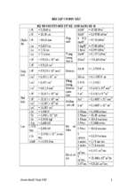
Figure 6
Determination of steel stress for crack width control
Table 11
Maximum bar size or spacing to limit crack width
wmax = 0.4 mm
Steel
stress
Maximum
Maximum
(s s)MPa bar
bar
size (mm)
spacing (mm)
wmax = 0.3 mm
Maximum
bar
size (mm)
Maximum
bar
spacing (mm)
160
40
300
32
300
200
32
25
240
20
OR 300
250
OR 250
200
280
16
200
12
150
320
12
150
10
100
360
10
100
8
50
16
Note
The steel stress may be estimated from the expression below (or see Figure 6):
ss =
fyk m As,req
gms n As,prov d
where
fyk
= characteristic reinforcement yield stress
gms
= partial factor for reinforcing steel
m
= total load from quasi-permanent combination
n
= total load from ULS combination
As,req = area of reinforcement at the ULS
As,prov = area of reinforcement provided
d
= ratio of redistributed moment to elastic moment
To determine stress in the reinforcement (ss), calculate the ratio Gk/Qk,
read up the graph to the appropriate curve and read across to determine ssu .
As,req
1
ss can be calculated from the expression: ss = ssu
As,prov d
(
)( )
7
15
2. Getting started
References
1 BRITISH STANDARDS INSTITUTION. BS EN 1992, Eurocode 2: Design of concrete structures. BSI (4 parts).
2 INSTITUTION OF STRUCTURAL ENGINEERS/THE CONCRETE SOCIETY. Standard method of detailing. ISE/CS. 2006.
3 NARAYANAN, R S & BROOKER, O. How to design concrete structures using Eurocode 2: Introduction to Eurocodes (TCC/03/16). The Concrete Centre, 2005.
4 BRITISH STANDARDS INSTITUTION. BS EN 1990, Eurocode: Basis of structural design. BSI, 2002.
5 BRITISH STANDARDS INSTITUTION. BS EN 1991, Eurocode 1: Actions on structures. BSI (10 parts).
6 BRITISH STANDARDS INSTITUTION. BS EN 1991, Eurocode 1: Actions on structures Part 1–1: General actions – Densities, self-weight, imposed loads
for buildings. BSI, 2002.
7 BRITISH STANDARDS INSTITUTION. BS 8500–1: Concrete – Complementary British Standard to BS EN 206–1– Part 1: Method of specifying and
guidance for the specifier. BSI, 2002.
8 BRITISH STANDARDS INSTITUTION. BS 4449: Specification for carbon steel bars for the reinforcement of concrete. BSI, 2005.
9 BRITISH STANDARDS INSTITUTION. Background paper to the UK National Annex to BS EN 1992–1–1. BSI, 2006.
10 BRITISH STAND ARDS INSTITUTION. BS EN 10080: Steel for the reinforcement of concrete – Weldable reinforcing steel – General. BSI, 2005.
11 BUILDING RESEARCH ESTABLISHMENT. Special Digest 1: Concrete in aggressive ground. BRE, 2005.
12 BRITISH STANDARDS INSTITUTION. BS EN 206–1: Concrete – Part: Specification, performance, production and conformity. BSI, 2000.
13 HARRISON, T A BROOKER, O. How to use BS 8500 with BS 8110 (TCC/03/11). The Concrete Centre, 2005.
14 BRITISH STANDARDS INSTITUTION. BS EN 1992–1–2, Eurocode 2: Design of concrete structures. General rules – structural fire design, BSI, 2004.
15 MOSS, R M & BROOKER, O. How to design concrete structures using Eurocode 2: Columns, (TCC/03/20). The Concrete Centre, 2006.
16