Tiêu chuẩn eurocode 2 1992.1.2.2004
Th
eEu
r
o
p
e
a
nUn
i
o
n
≠ EDI
CTOFGOVERNMENT±
I
no
r
d
e
rt
op
r
o
mo
t
ep
u
b
l
i
ce
d
u
c
a
t
i
o
na
n
dp
u
b
l
i
cs
a
f
e
t
y
,e
q
u
a
lj
u
s
t
i
c
ef
o
ra
l
l
,
ab
e
t
t
e
ri
n
f
o
r
me
dc
i
t
i
z
e
n
r
y
,t
h
er
u
l
eo
fl
a
w,wo
r
l
dt
r
a
d
ea
n
dwo
r
l
dp
e
a
c
e
,
t
h
i
sl
e
g
a
ld
o
c
u
me
n
ti
sh
e
r
e
b
yma
d
ea
v
a
i
l
a
b
l
eo
nan
o
n
c
o
mme
r
c
i
a
lb
a
s
i
s
,a
si
t
i
st
h
er
i
g
h
to
fa
l
lh
u
ma
n
st
ok
n
o
wa
n
ds
p
e
a
kt
h
el
a
wst
h
a
tg
o
v
e
r
nt
h
e
m.
EN 1992-1-2 (2004) (English): Eurocode 2: Design of concrete
structures - Part 1-2: General rules - Structural fire
design [Authority: The European Union Per Regulation
305/2011, Directive 98/34/EC, Directive 2004/18/EC]
EUROPEAN STANDARD
EN 1992-1-2
NORME EUROPEENNE
EUROpAISCHE NORM
December 2004
ICS 13.220.50; 91.010.30; 91.080.40
Supersedes ENV 1992-1-2:1995
Incorporating corrigendum July 2008
English version
Eurocode 2: Design of concrete structures - Part 1-2: General
rules - Structural fire design
Eurocode 2: Calcul des structures en beton Partie 1-2:
Regles generales Calcul du comportement au feu
Eurocode 2: Planung von Stahlbeton- und
Spannbetontragwerken TeiI1-2: Allgemeine Regeln Tragwerksbemessung fOr den Brandfall
This European Standard was approved by CEN on 8 July 2004.
CEN members are bound to comply with the CEN/CENELEC Internal Regulations which stipulate the conditions for giving this European
Standard the status of a national standard without any alteration. Up-to-date lists and bibliographical references concerning such national
standards may be obtained on application to the Central Secretariat or to any CEN member.
This European Standard exists in three official versions (English, French, German). A version in any other language made by translation
under the responsibility of a CEN member into its own language and notified to the Central Secretariat has the same status as the official
versions.
CEN members are the national standards bodies of Austria, Belgium, Cyprus, Czech Republic, Denmark, Estonia, Finland, France,
Germany, Greece, Hungary, Iceland, Ireland, Italy, Latvia, Lithuania, Luxembourg, Malta, Netherlands, Norway, Poland, Portugal, Slovakia,
Slovenia, Spain, Sweden, Switzerland and United Kingdom.
EUROPEAN COMMITTEE FOR STANDARDIZATION
COMITE EUROPEEN DE NORl\1ALrSATlON
EUROpAISCHES KOMITEE FUR NORMUNG
Management Centre: rue de Stassart, 36
© 2004 CEN
All rights of exploitation in any form and by any means reserved
worldwide for CEN national Members.
B·1050 Brussels
Ref. No. EN 1992-1-2:2004: E
BS EN 1992-1-2:2004
EN 1992-1-2:2004 (E)
Contents List
1
1.1
1.2
1.3
1.4
1.5
1.6
2
2.1
2.2
2.3
2.4
3
3.1
3.2
3.3
3.4
4
4.1
4.2
2
General
Scope
1.1.1 Scope of Eurocode 2
1.1.2 Scope of Part 1-2 of Eurocode 2
Normative references
Assurnptions
Distinctions between principles and application rules
Definitions
Symbols
1.6.1 Supplementary symbols to EN 1992-1-1
1.6.2 Supplementary subscripts to EN 1992-1-1
Basis of design
Requirements
2.1.1 General
2.1.2 Nominal fire exposure
2.1.3 Parametric fire exposure
Actions
Design values of material properties
Verification nlethods
2.4.1 General
2.4.2 Member analysis
2.4.3 Analysis of part of the structure
2.4.4 Global structural analysis
Material properties
General
Strength and defornlation properties at elevated temperatures
3.2.1 General
3.2.2 Concrete
3.2.2.1 Concrete under compression
3.2.2.2 Tensile strength
3.2.3 Reinforcing steel
3.2.4 Prestressing steel
Thermal and physical properties of concrete with siliceous and calcareous aggregates
3.3.1 Thermal elongation
3.3.2 Specific heat
3.3.3 Thermal conductivity
Thermal elongation of reinforcing and prestressing steel
Design procedures
General
Simplified calculation nlethod
4.2.1 General
4.2.2 Temperature profiles
4.2.3 Reduced cross-section
4.2.4 Strength reduction
4.2.4.1 General
BS EN 1992-1-2:2004
EN 1992-1-2:2004 (E)
4.3
4.4
4.5
4.6
4.7
4.2.4.2 Concrete
4.2.4.3 Steel
Advanced calculation methods
4.3.1 General
4.3.2 Thermal response
4.3.3 Mechanical response
4.3.4 Validation of advanced calculation models
Shear, torsion and anchorage
Spalling
4.5.1 Explosive spalling
4.5.2 Falling off of concrete
Joints
Protective layers
5
5.1
5.2
5.3
Tabulated data
Scope
General design rules
Columns
5.3.1 General
[§) 5.3.2 Method A
5.3.3 Method B @il
5.4
Walls
[§) 5.4.1 Non load bearing compartmentation walls @il
5.4.2 Load-bearing solid walls
5.4.3 Fire walls
5.5
Tensile members
5.6
Beams
5.6.1 General
5.6.2 Simply supported beams
5.6.3 Continuous beams
5.6.4 Beams exposed on all sides
5.7 Slabs
5.7.1 General
5.7.2 Simply supported solid slabs
5.7.3 Continuous solid slabs
5.7.4 Flat slabs
5.7.5 Ribbed slabs
6
6.1
6.2
6.3
6.4
High strength concrete (HSC)
General
Spalling
Thermal properties
Structural design
6.4.1 Calculation of load-carrying capacity
6.4.2 Simplified calculation method
6.4.2.1 Columns and walls
6.4.2.2 Beams and slabs
6.4.3 Tabulated data
3
BS EN 1992-1-2:2004
EN 1992-1-2:2004 (E)
Informative annexes
A
Temperature profiles
B
Simplified calculation methods
C
Buckling of columns under fire conditions
D
Calculation methods for shear, torsion and anchorage
E
Simplified calculation method for beams and slabs
Foreword
This European Standard EN 1992-1-2 , "Design of concrete structures - Part 1-2 General rules Structural fire design", has been prepared by Technical Committee CEN/TC250 "Structural
Eurocodes", the Secretariat of which is held by BSI. CEN/TC250 is responsible for all Structural
Eurocodes.
This European Standard shall be given the status of a National Standard, either by publication
of an identical text or by endorsement, at the latest by June 2005, and conflicting National
Standards shall be withdrawn at latest by March 2010.
This European standard supersedes ENV 1992-1-2: 1995.
According to the CEN-CENELEC Internal Regulations, the National Standard Organisations of
the following countries are bound to ilTlplement these European Standard: Austria, Belgium,
Cyprus, Czech Republic, Denmark, Estonia, Finland, France, Germany, Greece, Hungary,
Iceland, Ireland, Italy, Latvia, Lithuania, Luxembourg, Malta, Netherlands, Norway, Poland,
Portugal, Slovakia, Slovenia, Spain, Sweden, Switzerland and United Kingdom.
Background of the Eurocode programme
In 1975, the Commission of the European Community decided on an action progralTlme in the
field of construction, based on article 95 of the Treaty. The objective of the programme was the
elimination of technical obstacles to trade and the harmonisation of technical specifications.
Within this action programme, the Commission took the initiative to establish a set of harmonised
technical rules for the design of construction works which, in a first stage, would serve as an
alternative to the national rules in force in the Member States and, ultimately, would replace them.
For fifteen years, the Commission, with the help of a Steering Committee with Representatives
of Member States, conducted the development of the Eurocodes programme, which led to the
first generation of European codes in the 1980s.
In 1989, the Commission and the Member States of the EU and EFTA decided, on the basis of
1
an agreement between the Commission and CEN, to transfer the preparation and the
1 Agreement between the Commission of the European Communities and the European Committee for Standardisation (CEN) concerning the
work on EUROCODES for the design of building and civil engineering works (BC/CEN/03/89).
4
BS EN 1992-1-2:2004
EN 1992-1-2:2004 (E)
publication of the Eurocodes to the CEN through a series of Mandates, in order to provide them
with a future status of European Standard (EN). This links de facto the Eurocodes with the
provisions of all the Council's Directives and/or Commission's Decisions dealing with European
standards (e.g. the Council Directive 89/1 06/EEC on construction products - CPO - and Council
Directives 93/37/EEC, 92/50/EEC and 89/440/EEC on public works and services and equivalent
EFTA Directives initiated in pursuit of setting up the internal market).
The Structural Eurocode programme comprises the following standards generally consisting of
a number of Parts:
EN
EN
EN
EN
EN
EN
EN
EN
EN
EN
1990
1991
1992
1993
1994
1995
1996
1997
1998
1999
Eurocode:
Eurocode 1:
Eurocode 2:
Eurocode 3:
Eurocode 4:
Eurocode 5:
Eurocode 6:
Eurocode 7:
Eurocode 8:
Eurocode 9:
Basis of Structural Design
Actions on structures
Design of concrete structures
Design of steel structures
Design of composite steel and concrete structures
Design of timber structures
Design of masonry structures
Geotechnical design
Design of structures for earthquake resistance
Design of aluminium structures
Eurocode standards recognise the responsibility of regulatory authorities in each Member State
and have safeguarded their right to determine values related to regulatory safety matters at
national level where these continue to vary from State to State.
Status and field of application of Eurocodes
The Mernber States of the EU and EFTA recognise that Eurocodes serve as reference
documents for the following purposes:
as a means to prove compliance of building and civil engineering works with the essential
requirements of Council Directive 89/106/EEC, particularly Essential Requirement N°1 Mechanical resistance and stability - and Essential Requirement N°2 Safety in case of fire;
as a basis for specifying contracts for construction works and related engineering services;
as a framework for drawing up harmonised technical specifications for construction products
(ENs and ETAs)
The Eurocodes, as far as they concern the construction works themselves, have a direct
relationship with the Interpretative Documents2 referred to in Article 12 of the CPO, although
they are of a different nature from harmonised product standards3. Therefore, technical aspects
arising from the Eurocodes work need to be adequately considered by CEN Technical
2 According to Art. 3.3 of the CPD, the essential requirements (ERs) shall be given concrete form in interpretative documents for the creation of
the necessary links between the essential requirements and the mandates for harmonised ENs and ETAGs/ETAs.
3 According to Art. 12 of the CPD the interpretative documents shall :
a) give concrete form to the essential requirements by harmonising the terminology and the technical bases and indicating classes or levels for each
requirement where necessary;
b) indicate methods of correlating these classes or levels of requirement with the technical specifications, e.g. methods of calculation and of proof,
technical rules for project design, etc. ,
c)
serve as a reference for the establishment of harmonised standards and guidelines for European technical approvals.
The Eurocodes, de facto, playa similar role in the field of the ER 1 and a part of ER 2.
5
BS EN 1992-1-2:2004
EN 1992-1-2:2004 (E)
Comnlittees and/or EOTA Working Groups working on product standards with a view to
achieving full compatibility of these technical specifications with the Eurocodes.
The Eurocode standards provide common structural design rules for everyday use for the
design of whole structures and COITlpOnent products of both a traditional and an innovative
nature. Unusual forms of construction or design conditions are not specifically covered and
additional expert consideration will be required by the designer in such cases.
National Standards implementing Eurocodes
The National Standards implementing Eurocodes will comprise the full text of the Eurocode
(including any annexes), as published by CEN, which may be preceded by a National title page
and National foreword, and may be followed by a National Annex.
The National Annex may only contain information on those parameters which are left open in
the Eurocode for national choice, known as Nationally DeterITlined Parameters, to be used for
the design of buildings and civil engineering works to be constructed in the country concerned,
i.e. :
- values and/or classes where alternatives are given in the Eurocode,
- values to be used where a symbol only is given in the Eurocode,
- country specific data (geographical, climatic, etc.), e.g. snow map,
- the procedure to be used where alternative procedures are given in the Eurocode,
- decisions on the application of informative annexes,
- references to non-contradictory complementary information to assist the user to apply the
Eurocode.
Links between Eurocodes and products harmonised technical specifications (ENs and
ETAs)
There is a need for consistency between the harmonised technical specifications for
construction products and the technical rules for works4. Furthermore, all the information
accompanying the CE Marking of the construction products which refer to Eurocodes should
clearly mention which Nationally Determined Parameters have been taken into account.
Additional information specific to EN 1992-1-2
EN 1992- 1-2 describes the Principles, requirements and rules for tile structural design of
buildings exposed to fire, including the following aspects.
Safety requirements
EN 1992-1-2 is intended for clients (e.g. for the formulation of their specific requirements),
designers, contractors and relevant authorities.
The general objectives of fire protection are to limit risks with respect to the individual and
society, neighbouring property, and where required, environment or directly exposed property,
in the case of fire.
4
6
see Art.3.3 and Art.12 of the CPO, as well as clauses 4.2, 4.3.1, 4.3.2 and 5.2 of 10 1.
BS EN 1992-1-2:2004
EN 1992-1-2:2004 (E)
Construction Products Directive 89/1 06/EEC gives the following essential requirement for the
limitation of fire risks:
"The construction works must be designed and build in such a way, that in the event of an
outbreak of fire
- the load bearing resistance of the construction can be assumed for a specified period of
time
- the generation and spread of fire and smoke within the works are limited
- the spread of fire to neighbouring construction works is limited
- the occupants can leave the works or can be rescued by other means
- the safety of rescue teams is taken into consideration".
According to the Interpretative Document N° 2 "Safety in case of fire" the essential requirement
may be observed by following various possibilities for fire safety strategies prevailing in the
Member states like conventional fire scenarios (nominal fires) or "natural" (parametric) fire
scenarios, including passive and/or active fire protection measures.
The fire parts of Structural Eurocodes deal with specific aspects of passive fire protection in
terms of designing structures and parts thereof for adequate load bearing resistance and for
limiting fire spread as relevant.
Required functions and levels of performance can be specified either in terms of nominal
(standard) fire resistance rating, generally given in national fire regulations or by referring to fire
safety engineering for assessing passive and active measures, see EN 1991-1-2.
Supplementary requirements concerning, for example:
- the possible installation and maintenance of sprinkler systems,
- conditions on occupancy of building or fire compartment,
- the use of approved insulation and coating materials, including their maintenance,
are not given in this document, because they are subject to specification by the competent
authority.
Numerical values for partial factors and other reliability elements are given as recommended
values that provide an acceptable level of reliability. They have been selected assuming that an
appropriate level of workmanship and of quality management applies.
Design procedures
A full analytical procedure for structural fire design would take into account the behaviour of the
structural system at elevated temperatures, the potential heat exposure and the beneficial
effects of active and passive fire protection systems, together with the uncertainties associated
with these three features and the importance of the structure (consequences of failure).
At the present time it is possible to undertake a procedure for determining adequate
performance which incorporates some, if not all, of these parameters and to demonstrate that
the structure, or its components, will give adequate performance in a real building fire. However,
where the procedure is based on a nonlinal (standard) fire the classification system, which call
for specific periods of fire resistance, takes into account (though not explicitly), the features and
uncertainties described above.
7
BS EN 1992-1-2:2004
EN 1992-1-2:2004 (E)
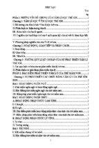
Application of design procedures is illustrated in Figure 0.1. The prescriptive approach and the
performance-based approach are identified. The prescriptive approach uses nominal fires to
generate thermal actions. The performance-based approach, using fire safety engineering,
refers to thermal actions based on physical and chemical parameters. Additional information for
alternative methods in this standard is given in Table 0.1.
For design according to this part, EN 1991-1-2 is required for the determination of thermal and
mechanical actions to the structure.
Design aids
Where simple calculation models are not available, the Eurocode fire parts give design
solutions in terms of tabulated data (based on tests or advanced calculation models), which
may be used within the specified limits of validity.
It is expected, that design aids based on the calculation models given in EN 1992-1-2, will be
prepared by interested external organisations.
The main text of EN 1992-1-2, together with informative Annexes A, B, C, D and E, includes
most of the principal concepts and rules necessary for structural fire design of concrete
structures.
National Annex for EN 1992-1-2
This standard gives alternative procedures, values and recommendations for classes with notes
indicating where national choices may have to be made. Therefore the National Standard
implementing EN 1992-1-2 should have a National Annex containing the Eurocode all Nationally
Determined Parameters to be used for the design of buildings, and where required and
applicable, for civil engineering works to be constructed in the relevant country.
National choice is allowed in EN 1992-1-2 through clauses:
- 2.1.3 (2)
- 2.3 (2)P
- 3.2.3 (5)
- 3.2.4 (2)
- 3.3.3 (1)
-4.1 (1)P
- 4.5.1 (2)
- 5.2 (3)
8
-
5.3.2 (2)
5.6.1 (1)
5.7.3 (2)
6.1 (5)
6.2 (2)
6.3.1 (1)
6.4.2.1 (3)
6.4.2.2 (2)
8S EN 1992·1·2:2004
EN 1992-1-2:2004 (E)
I
I
I
I
I
I(Thennal Actions
Ple~II~lVe Rul~
I
given by Nominal Fire
Penormalce-Based Code
(Physically based Thermal Actions)
I
I
I
Member
Analysis
I
Tabulated
Data
I
of the Structure
Analysis of
Entire SlrLlCture
II
I
ISeleclim of ~mple
01 Mvanr:ei
Fire Development Models
I
I
I
I
I
I
Calculation of
Mechanical Actions
at Boundaries
Calculation of
Mechanical Actions
at Boundaries
Selection of
Mechanical
Actions
Member
Analysis
I
i
I
I
I
[§)Sim plified
Calculation
Models@j]
I
I
Advanced
Calculation
Models
~implified
Calculation
Models@j]
(if available)
I
I
Part aftne
Siructure
Analysis of
Entire
Structure
I
I
I
I
Advanced
Calculation
Models
Calculation of
Mechanical
Mions
at Boundaries
Calculation of
Mechanical
Actions
at Boundaries
Selection of
Mechanical
Actions
I
Advanced
Calculation
Models
I
I
I
I
I
I
~Simplified
Advanced
Calculation
Models
Advanced
Calculation
Models
Advanced
Calculation
Models
Calculation
Models@j]
(if available)
Figure 1 : Alternative design procedures
Table 0.1 Summary table showing alternative methods of verification for 'fire resistance
Tabulated data
Simplified calcul
methods
Member analysis
YES
YES
The member is
considered as isolated.
Indirect fire actions are
not considered, except
those resulting from
thermal gradients
- Data given for standard
fire only, 5 .. 1(1)
- In principle data could
be developed for other
fire curves
- standard fire and
parametric fire, 4.2.1 (1)
- temperature profiles
given for standard fire
only, 4.2.2(1)
- material models apply
only to heating rates
similar to standard fire,
4.2.4.1 (2)
~Analysis of part of the NO
structure
Indirect fire actions
within the subassembly
are considered, @11
but no time-dependent
interaction with other
parts of the structure.
Global structural
analysis
Analysis of the entire
structure. Indirect fire
actions are considered
throughout the structure
YES
- standard fire and
parametric fire, 4.2.1(1)
- temperature profiles
given for standard fire
only, 4.2.2(1)
- material models apply
only to heating rates
similar to standard fire,
4,2.4.1 (2)
NO
NO
A
ed calculation
models
YES,
4.3.1(1)P
Only the principles are
given
YES
4.3.1(1)P
Only the principles are
given
YES
4.3.1 (1)P
Only the principles are
given
9
BS EN 1992-1-2:2004
EN 1992-1-2:2004 (E)
SECTION 1
1.1
GENERAL
Scope
1.1.1 Scope of Eurocode 2
(1)P Eurocode 2 applies to the design of buildings and civil engineering works in concrete. It
complies with the principles and requirements for the safety and serviceability of structures, the
basis of their design and verification that are given in EN 1990 Basis of structural design.
(2)P Eurocode 2 is only concerned with requirements for resistance, serviceability, durability
and fire resistance concrete structures. Other requirements, e.g. concerning thermal or sound
insulation, are not considered.
(3)P Eurocode 2 is intended to be used in conjunction with:
- EN 1990 "Basis of structural design"
-- EN 1991 "Actions on structures"
hEN's for construction products relevant for concrete structures
ENV 13670-1 "Execution of concrete structures. Part 1: Common rules"
EN 1998 "Design of structures for earthquake resistance", when concrete structures are
built in seisrnic regions
(4)P Eurocode 2 is subdivided in various parts:
- Part 1-1: General rules and rules for buildings
- Part 1-2: General rules - Structural fire design
- Part 2: Concrete bridges
- Part 3: Liquid retaining and containment structures
1.1.2 Scope of Part 1-2 of Eurocode 2
(1)P This Part 1-2 of EN 1992 deals with the design of concrete structures for the accidental
situation of fire exposure and is intended to be used in conjunction with EN 1992-1-1 and
EN 1991-1-2. This part 1-2 only identifies differences from, or supplements to, normal
temperature design.
(2)P This Part 1-2 of EN 1992 deals only with passive methods of fire protection. Active methods
are not covered.
(3)P This Part 1-2 of EN 1992 applies to concrete structures that are required to fulfil certain
functions when exposed to fire, in terms of:
- avoiding premature collapse of the structure (load bearing function)
- limiting fire spread (flame, hot gases, excessive heat) beyond designated areas (separating
function)
(4)P This Part 1-2 of EN 1992 gives principles and application rules (see EN 1991-1-2) for
designing structures for specified requirements in respect of the aforementioned functions and
the levels of performance.
10
BS EN 1992-1-2:2004
EN 1992-1-2:2004 (E)
(5)P This Part 1-2 of EN 1992 applies to structures, or parts of structures, that are within the
scope of EN 1992-1-1 and are designed accordingly. However, it does not cover:
- structures with prestressing by external tendons
- shell structures
(6)P The methods given in this Part 1-2 of EN 1992 are applicable to normal weight concrete up
to strength class C90/105 and for lightweight concrete up to strength class LC55/60. Additional
and alternative rules for strength classes above C50/60 are given in section 6.
1.2
Normative references
The following normative documents contain provisions that, through reference in this text,
constitute provisions of this European Standard. For dated references, subsequent
amendments to, or revisions of, any of these publications do not apply. However, parties to
agreements based on this European Standard are encouraged to investigate the possibility of
applying the most recent editions of the normative documents indicated below. For undated
references, the latest edition of the normative document referred to applies.
EN 1363-2: Fire resistance tests - Part 2: Alternatives and additional procedures;
EN 1990: Eurocode: Basis of structural design;
EN 1991-1-2: Eurocode 1 - Actions on structures - Part 1-2: General actions - Actions on
structures exposed to fire;
EN 1992-1-1: Eurocode 2. Design of concrete structures - Part 1.1: General rules and rules for
buildings
EN 10080: Steel for the reinforcement of concrete - Weldable reinforcing steel - General
EN 10138-2: Prestressing steels - Part 2: Wire
EN 10138-3: Prestressing steels - Part 3: Strand
EN 10138-4: Prestressing steels - Part 4: Bar
1.3
Assumptions
m1>The general assumptions given in EN 1990 and EN 1992-1-1 apply. @j]
1.4
Distinction between principles and application rules
(1) The rules given in EN 1990 apply.
1.5
Definitions
For the purposes of this Part 1-2 of EN 1992, the definitions of EN 1990 and of EN 1991-1-2
apply with the additional definitions:
1.5.1 Critical temperature of reinforcement: The temperature of reinforcement at which failure
of the member in fire situation (Criterion R) is expected to occur at a given steel stress level.
1.5.2 Fire wall: A wall separating two spaces (generally two buildings) that is designed for fire
resistance and structural stability, and may include resistance to horizontal loading such that, in
case of fire and failure of the structure on one side of the wall, fire spread beyond the wall is
avoided.
11
BS EN 1992-1-2:2004
EN 1992-1-2:2004 (E)
1.5.3 Maximum stress level: For a given temperature, the stress level at which the stressstrain relationship of steel is truncated to provide a yield plateau.
1.5.4 Part of structure: isolated part of an entire structure with appropriate support and
boundary conditions.
1.5.5 Protective layers: Any material or combination of materials applied to a structural
member for the purpose of increasing its fire resistance.
1.5.6 Reduced cross section: Cross section of the member in structure fire design used in the
reduced cross section method. ~ It is obtained by removing parts of the @j] cross section with
assumed zero strength and stiffness.
1.6
Symbols
1.6.1 Supplementary symbols to EN1992 .. 1-1
(1)P The following supplementary symbols are used:
Latin upper case letters
Ed,fi
design effect of actions in the fire situation
Ed
design effect of actions for normal temperature design
Rd,fi
design resistance in the fire situation; Rd,fi(t) at a given time t.
R 30 or R 60, ... fire resistance class for the load-bearing criterion for 30, or 60 ... minutes in
standard fire exposure
E 30 or E 60, ... fire resistance class for the integrity criterion for 30, or 60 ... minutes in standard
fire exposure
I 30 or I 60, ... fire resistance class for the insulation criterion for 30, or 60 ... minutes in standard
fire exposure
e
T
temperature [K] (cf
Xk
characteristic value of a strength or deformation property for normal temperature design
Xd,fi
design strength or deformation property in the fire situation
temperature [OC]);
Latin lower case letters
a
axis distance of reinforcing or prestressing steel from the nearest exposed surface
Cc
specific heat of concrete [J/kgK]
fck (B)
characteristic value of compressive strength of concrete at temperature Bfor a specified
strain
fck,t(B) characteristic value of tensile strength of concrete at temperature tJfor a specified strain
12
BS EN 1992-1-2:2004
EN 1992·1·2:2004 (E)
fpk( B) characteristic value of strength of prestressing steel at temperature afor a specified strain
fsk ( a) characteristic strength of reinforcing steel at temperature afor a specified strain
k( B)= X k ( B)/Xk reduction factor for a strength or deformation property dependent on the material
temperature
~
a
n=
NOEd,fi
t
time in fire exposure (min)
/(O,7(Ac
fed
+ As
fyd ))
load level of a column at normal temperature conditions
Greek lower case letters
/M,fi
paliial safety factor for a material in fire design
7]fi
= Ed,t/Ed reduction factor for design load level in the fire situation
Jifi
= NEd,fi INRd degree of utilisation in fire situation
&c(8)
thernlal strain of concrete
&p(8)
thermal strain of prestressing steel
Gs(8)
thermal strain of reinforcing steel
strain of the reinforcing or prestressing steel at temperature
Ac
thermal conductivity of concrete [W/mK]
Ao,fi
slenderness of the column under fire conditions
O"c,fi
compressive stress of concrete in fire situation
O"s,fi
steel stress in fire situation
a
temperature [OC]
acr
critical temperature [OC]
a
1.6.2 Supplementary to EN 1992-1-1, the following subscripts are used:
fi
value relevant for the fire situation
t
dependent on the time
B
dependent on the temperature
13
BS EN 1992-1-2:2004
EN 1992-1-2:2004 (E)
SECTION 2
2.1
BASIS OF DESIGN
Requirements
2.1.1 General
(1)P Where mechanical resistance in the case of fire is required, concrete structures shall be
designed and constructed in such a way that they maintain their load bearing function ~ during
the required time of fire exposure. @il
(2)P Where compartmentation is required, the elements forming the boundaries of the fire
compartment, including joints, shall be designed and constructed in such a way that they maintain
their separating function ~ during the required time of fire exposure. @il This shall ensure, where
relevant, that:
- integrity failure does not occur, see EN 1991-1-2
- insulation failure does not occur, see EN 1991-1-2
- thermal radiation from the unexposed side is limited.
Note 1: See EN 1991-1-2 for the definitions.
Note 2: For concrete structures considered in this Part 1-2 thermal radiation criteria are not relevant.
(3)P Deformation criteria shall be applied where the means of protection, or the design criteria for
separating elements, require consideration of the deformation of the load bearing structure.
(4) Consideration of the deformation of the load bearing structure is not necessary in the
following cases, as relevant:
- the efficiency of the means of protection has been evaluated according to 4.7,
- the separating elements have to fulfil requirements according to nominal fire exposure.
2.1.2 Nominal fire exposure
(1)P For the standard fire exposure, members shall comply with criteria R, E and I as follows:
- separating only: integrity (criterion E) and, when requested, insulation (criterion I)
load bearing only: mechanical resistance (criterion R)
- separating and load bearing: criteria R, E and, when requested I
(2) Criterion "R" is assumed to be satisfied where the load bearing function is maintained
during the required time of fire exposure.
(3) Criterion "I" may be assumed to be satisfied where the average temperature rise over the
whole of the non-exposed surface is limited to 140 K, and the maximum tern perature rise at any
point of that surface does not exceed 180 K
(4) ~ With the external fire exposure curve (see EN 1991-1-2) the same criteria (R, E, I) should
apply, however the reference to this specific curve should be identified by the letters "ef'. @il
(5) ~ With the hydrocarbon fire exposure curve (see EN 1991-1-2) the same criteria (R, E, I)
should apply, however the reference to this specific curve should be identified by the letters "HC~' @il
14
BS EN 1992-1-2:2004
EN 1992-1-2:2004 (E)
(6) Where a vertical separating element with or without load-bearing function has to comply
with impact resistance requirement (criterion M), the element should resist a horizontal
concentrated load as specified in EN 1363 Part 2.
2.1.3 Parametric fire exposure
~(1)P The load-bearing function shall @il be maintained during the complete endurance of the
fire including the decay phase, or a specified period of time.
(2) For the verification of the separating function the following applies, assurning that the
normal terTI perature is 20°C:
- the average temperature rise of the unexposed side of the construction should be limited to
140 K and the maximum temperature rise of the unexposed side should not exceed 180 K
during the heating phase until the maximum gas temperature in the fire compartment is
reached;
- the average temperature rise of the unexposed side of the construction should be limited to
~()1 and the maximum temperature rise of the unexposed side should not exceed ~fh during
the decay phase.
Note: The values of ,101 and
for use in a Country may be found in its National Annex. The recommended
values are ,101 = 200 K and ,1B.z 240 K.
Actions
2.2
(1)P The thermal and mechanical actions shall be taken from EN 1991-1-2.
(2) In addition to EN 1991-1-2, the emissivity related to the concrete surface should be taken as
0,7.
Design values of material properties
2.3
(1)P Design values of mechanical (strength and defornlation) material properties Xd,fi are defined
as follows:
Xd,fi
= ke
X k / }1vI,fi
(2.1)
where:
Xk
ko
}1vI,fi
is the characteristic value of a strength or deformation property (generally fk or Ek) for
normal terTlperature design to EN 1992-1-1;
is the reduction factor for a strength or deformation property (Xk,e/ Xk), dependent on
the material temperature, see 3.2.;
is the partial safety factor for the relevant material property, for the fire situation.
(2)P Design values of thermal material properties Xd,fi are defined as follows:
- if an increase of the property is favourable for safety:
Xd,fi
= Xk,o / }1vI,fi
(2.2a)
if an increase of the property is unfavourable for safety:
(2.2b)
where:
15
BS EN 1992 .. 1-2:2004
EN 1992-1-2:2004 (E)
X k,8 is the value of a material property in fire design, generally dependent on the material
temperature, see section 3;
/1v1,fi is the partial safety factor for the relevant material property, for the fire situation.
Note 1: The value of J1-~,fi for use in a Country may be found in its National Annex. The recommended value is:
For thermal properties of concrete and reinforcing and prestressing steel: }'M,fi
1,0
For mechanical properties of concrete and reinforcing and prestressing steel: YM,fi = 1,0
=
Note 2: If the recommended values are modified, the tabulated data may require modification.
2.4
Verification methods
2.4.1 General
(1)P The model of the structural system adopted for design to this Part 1.2 of EN 1992 shall
reflect the expected performance of the structure in fire.
It shall be verified for the specified duration of fire exposure
(2)P
t : @i]
(2.3)
where
Ed,fi
Rd,t,fi
is the design effect of actions for the fire situation, determined in accordance with
EN 1991-1-2, including effects of thermal expansions and deformations
is the corresponding design resistance in the fire situation.
(3) The structural analysis for the fire situation should be carried out according to Section 5 of
EN 1990.
Note: For verifying standard fire resistance requirements, a member analysis is sufficient.
(4) Where application rules given in this Part 1-2 are valid only for the standard temperature-time
curve, this is identified in the relevant clauses
(5) Tabulated data given in section 5 are based on the standard temperature-time curve.
(6)P As an alternative to design by calculation, fire design may be based on the results of fire
tests, or on fire tests in combination with calculations, see EN 1990, Section 5.
2.4.2 Member analysis
(1) The effect of actions should be determined for time
If/1,2 according to EN 1991-1-2 Section 4.
t= 0
using combination factors
'1/1,1
or
(2) As a simplification to (1) the effects of actions may be obtained from a structural analysis for
normal temperature design as:
(2.4)
Where
17fi
is the design value of the corresponding force or moment for normal temperature
design, for a fundamental combination of actions (see EN 1990);
is the reduction factor for the design load level for the fire situation.
(3) The reduction factor lJfi for load combination (6.10) in EN 1990 should be taken as:
16
BS EN 1992-1-2:2004
EN 1992-1-2:2004 (E)
(2.5)
or for load combination (6.1 Oa) and (6.1 Db) in EN 1990 as the smaller value given by the two
following expressions:
(2.5a)
17fi =
(2.5b)
where
is the principal variable load;
Gk is the characteristic value of a permanent action;
YG is the partial factor for a permanent action;
Ya,1 is the partial factor for variable action 1;
is the combination factor for frequent or quasi-permanent values given either by
ljIfi
or ljI2,1, see EN1991-1-2
is a reduction factor for unfavourable permanent action G
Qk,1
ljI1,1
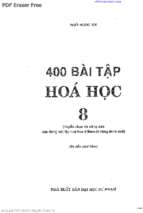
Note 1: Regarding equation (2.5), examples of the variation of the reduction factor 'lfi versus the load ratio
Qk,1/Gk for Expression (2.4) and different values of the combination factor V/1,1 are shown in Figure 2.1 with the
following assumptions: YGA = 1,0, YG 1,35 and Yo = 1,5. Expressions (2.5a) and (2.5b) give slightly higher
values. Recommended values of partial factors are given in the relevant National Annexes of EN 1990.
Note 2: As a simplification a recommended value of 'lfi
=0,7 may be used.
0,8
1Jfi
0,7 ~ "-
~ ~ r-- r-\ ~ ~ r---.....
0,6
r--- r-~~
0,5
"
"
0,4
,~
-..... r--......
"'- ........ ........
0,3
1,1/1,1=
0,9
-
- ""--J____
~
- ----r--..
r--- r---
1,1/1,1
=0,2
0,2
0,0
0,5
1,0
1,5
2,0
Figure 2.1: Variation of the reduction factor llfi with the load ratio Qk,1/ Gk
(4) Only the effects of thermal defornlations resulting from thermal gradients across the crosssection need be considered. The effects of axial or in-plane thermal expansions may be
neglected.
17
BS EN 1992-1-2:2004
EN 1992-1-2:2004 (E)
(5) The boundary conditions at supports and ends of member, applicable at time t = 0, are
assunled to remain unchanged throughout the fire exposure.
(6) Tabulated data, simplified or general calculation methods given in 5, 4.2 and 4.3
respectively are suitable for verifying members under fire conditions.
2.4.3 Analysis of part of the structure
(1) 2.4.2 (1) applies.
°
(2) As an alternative to carrying out a global structural analysis for the fire situation at time t =
the reactions at supports and internal forces and moments at boundaries of part of the structure
may be obtained from structural analysis for normal temperature as given in 2.4.2
(3) The part of the structure to be analysed should be specified on the basis of the potential
thernlal expansions and deformations such, that their interaction with other parts of the
structure can be approximated by time-independent support and boundary conditions during fire
exposure.
(4)P Within the part of the structure to be analysed, the relevant failure mode in fire exposure,
the temperature-dependent material properties and nlember stiffnesses, effects of thermal
expansions and deformations (indirect fire actions) shall be taken into account
(5) The boundary conditions at supports and forces and moments at boundaries of part of the
structure, applicable at time t = 0, are assumed to remain unchanged throughout the fire
exposure
2.4.4 Global structural analysis
(1)P When global structural analysis for the fire situation is carried out, the relevant failure
mode in fire exposure, the ternperature-dependent material properties and member stiffnesses,
effects of thermal expansions and deformations (indirect fire actions) shall be taken into
account.
18
- Xem thêm -