Explosion-Proof Type
Operation
Manual
操作説明書
Kawasaki Heavy Industries, Ltd.
Caution
Read this manual carefully before you use the robot
actually and keep it safe, so as to fully bring out the
functions of your Kawasaki Robot for yourself.
90203-1075DEB
COPYRIGHTED DOCUMENT - INTENDED FOR CUSTOMER REFERENCE ONLY
C Series Controller
For safety
FOR SAFETY
This operation manual and the labels on the products are indicated with the symbols below for
proper use and to avoid injuries or property damage.
Read this manual and the related documents thoroughly before installation, operation,
maintenance and inspection.
!
DANGER
Identifies procedures that, if not properly followed, can
result in imminent injury or death.
!
WARNING
Identifies procedures that, if not properly followed, may
possibly lead to injury or death.
!
CAUTION
Identifies procedures that, if not properly followed, may
lead to human and/or mechanical injury.
[ NOTE ]
Denotes easily-misunderstood items regarding product
performance, operation, and maintenance.
i
COPYRIGHTED DOCUMENT - INTENDED FOR CUSTOMER REFERENCE ONLY
C Series Controller, Explosion-Proof Type
Kawasaki Robot Operation Manual
For safety
PREFACE
This manual describes operational procedures for the Kawasaki C Series Controller,
Explosion-Proof Type.
Please read the Safety Manual thoroughly, a separate volume, before reading this manual.
Also, this manual should be read before actual operation of the robot, and be stored for
safe-keeping for later reference.
This manual is written on the following assumptions:
The robot is installed according to the Installation and Connection Manual (for robot arm), a
separate volume.
The controller is installed and connected according to the Installation and Connection Manual
(for robot controller), a separate volume.
The peripheral equipment is connected with the controller according to the External I/O Manual,
a separate volume.
This manual intends to explain the operational procedures as detailed as possible. As not all
operations can be explained in one manual, only the major functions are explained.
Therefore, only the operation of functions specifically described herein can be guaranteed.
Because Kawasaki constantly strives to improve the quality of its products, this manual may
be changed or revised without prior notice.
This manual may not, in whole or in part, be reproduced or copied without the prior written
consent of Kawasaki.
Though this manual was prepared to be as thorough and accurate as possible, the authors
apologize should any information be found in error.
The screen examples in this manual may differ depending on software version.
Some functions may not be installed depending on software version.
This manual concerns operating procedures. It is not a guarantee of safety, and Kawasaki
is not responsible for damages by the system or any industrial property troubles related with
patent, as in the event of unforeseen trouble.
MS-DOS is a registered trademark of Microsoft Corporation, USA.
The other company and product names are also registered.
All rights reserved. Copyright @ 2001 by KAWASAKI HEAVY INDUSTRIES, LTD.
ii
COPYRIGHTED DOCUMENT - INTENDED FOR CUSTOMER REFERENCE ONLY
C Series Controller, Explosion-Proof Type
Kawasaki Robot Operation Manual
For safety
BASIC CONFIGURATION OF THIS MANUAL
This manual describes the fundamental operational procedures for the Kawasaki C Series
Controller, Explosion-Proof Type.
Overview and basic operations that need to be understood first for using Kawasaki Robot
Controller are explained. Operations which are common in every application and are peculiar to
painting application are included and need to be read thoroughly.
Many functions for making full use of the controller are also explained and should be read
depending on the aim of the user.
A glossary is included at the end of the manual as a reference for commonly used language and
keywords regarding robots.
The ) indicates a reference. For example, ) A-142 indicates that the auxiliary function 142
should be referenced.
iii
COPYRIGHTED DOCUMENT - INTENDED FOR CUSTOMER REFERENCE ONLY
C Series Controller, Explosion-Proof Type
Kawasaki Robot Operation Manual
For safety
TEACHING METHODS
The Kawasaki C Series Controller, Explosion-Proof Type can be programmed by a variety of
equipment including the explosion-proof teach pendant.
Select a teaching method that best suits the needs of your application and level of expertise.
Explosion-proof teach pendant:
Manual operation and teaching for the
robot can be conducted using the
explosion-proof teach pendant.
Manual operation can be conducted
only by the teach pendant.
Multifunction panel:
Various data can be displayed and set
using the multifunction panel. Its
keyboard screen is used for
programming.
PC (Option):
It is possible to create an advanced
application program by entering program
instructions on PC. (This is called
general programming.) Robot
Language (AS Language) functions can
be fully used, so that programs using
advanced functions, such as coating
operations, communication, and vision
sensing, are possible.
iv
COPYRIGHTED DOCUMENT - INTENDED FOR CUSTOMER REFERENCE ONLY
C Series Controller, Explosion-Proof Type
Kawasaki Robot Operation Manual
For safety
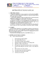
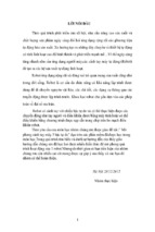
SYSTEM STRUCTURE
The system structure of the Kawasaki C Series Controller, Explosion-Proof Type is as follows:
Kawasaki
Robot
C Series
Controller
Multifunction Panel
Explosion-Proof
Teach Pendant
Peripheral
Equipment
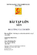
Multifunction Panel
PC
Explosion-Proof Type
Controller
PC
(Prepared by the user)
Explosion-Proof Teach Pendant
KOSMOS Monitoring
Software [For PC] (Provided
by Kawasaki; Optional)
[ NOTE ]
Monitoring software for PC is
run by the OS such as MS-DOS.
OS needs to be prepared by the
user.
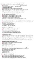
Multifunction Panel
Controller
Program selection
Displays programs and steps
Monitoring the signals
Setting the repeat conditions
General teaching
Explosion-Proof Teach Pendant
Regular operation
Program selection
Programs and steps Display
Manual operation of the robot
Monitoring the signals
Setting the repeat conditions
Positional teaching
General teaching
v
PC
Instruction entry of AS Language
Keyboard entry of AS Language
programs
Loading/Saving of the programs
into/from disk
COPYRIGHTED DOCUMENT - INTENDED FOR CUSTOMER REFERENCE ONLY
C Series Controller, Explosion-Proof Type
Kawasaki Robot Operation Manual
Contents
CONTENTS
SAFETY
1 ENSURING SAFETY.......................................................................................... 2
2 SAFETY IN GENERAL....................................................................................... 2
3 ROBOT SPEED LIMITATIONS.......................................................................... 3
4 ROBOT MOTION RANGE ................................................................................. 3
5 FIVE SAFETY RULES TO BE OBSERVED FOR KHI ROBOTS...................... 4
6 SAFETY DURING START-UP ........................................................................... 7
7 ENSURING SAFETY DURING TEACHING OPERATIONS............................. 8
8 DANGER PREVENTION DURING OPERATIONS........................................... 9
1 SWITCHES AND KEYS
1.1 SWITCHES ON THE CONTROLLER...........................................................1-2
1.2 MULTIFUNCTION PANEL ............................................................................1-4
1.2.1 SWITCHES ON THE MULTIFUNCTION PANEL ...................................1-4
1.2.2 LIQUID CRYSTAL DISPLAY ...................................................................1-5
1.2.3 KEYS ON THE LIQUID CRYSTAL DISPLAY .........................................1-6
1.2.4 KEYBOARD..............................................................................................1-7
1.3 EXPLOSION-PROOF TEACH PENDANT....................................................1-8
1.3.1 KEYS AND SWITCHES ...........................................................................1-8
1.3.2 DISPLAY DURING TEACHING.............................................................1-13
2 PROCEDURES FOR POWER ON/OFF AND STOPPING THE ROBOT
MOTION
2.1 TURNING THE POWER ON.........................................................................2-2
2.2 TURNING THE POWER OFF .......................................................................2-5
2.3 STOPPING THE ROBOT MOTION ..............................................................2-6
3 BASIC OPERATION OF MULTIFUNCTION PANEL
3.1 SWITCHING THE SCREEN OF THE MULTIFUNCTION PANEL ...............3-2
3.1.1 BASIC SCREEN STRUCTURE ON THE MULTIFUNCTION
PANEL
..............................................................................................3-4
3.1.2 STATUS SCREEN ...................................................................................3-5
3.1.3 OTHERS .............................................................................................. 3-6
3.1.4 STATUS SCREEN ...................................................................................3-8
3.1.5 SPRAY STATUS SCREEN......................................................................3-9
3.1.6 PROGRAM LIST SCREEN....................................................................3-13
3.1.7 MONITOR SCREEN ..............................................................................3-14
3.1.8 CURRENT POSITION SCREEN ...........................................................3-17
3.2 MOVING CURSORS ...................................................................................3-18
3.3 SELECTION BY ENTERING NUMERIC VALUES OR USING
CURSOR OPERATION...............................................................................3-19
3.4 ENTERING CHARACTERS ........................................................................3-20
3.5 SELECTING PROGRAMS ..........................................................................3-21
3.6 SELECTING STEPS....................................................................................3-23
vi
COPYRIGHTED DOCUMENT - INTENDED FOR CUSTOMER REFERENCE ONLY
C Series Controller, Explosion-Proof Type
Kawasaki Robot Operation Manual
Contents
4 MANUAL OPERATION
4.1 KEYS USED FOR MANUAL OPERATION...................................................4-2
4.2 PROCEDURES FOR MANUAL OPERATION..............................................4-3
4.2.1 TYPES OF THE MANUAL OPERATION COORDINATE SYSTEM.......4-5
4.2.2 SELECTING THE MANUAL OPERATION COORDINATE
SYSTEM ..............................................................................................4-5
4.2.3 SELECTING THE MANUAL OPERATION SPEED ................................4-5
4.2.4 MANUAL OPERATION ON THE JOINT COORDINATE SYSTEM........4-6
4.2.5 MANUAL OPERATION ON THE CARTESIAN COORDINATE
SYSTEM ..............................................................................................4-9
4.2.6 MANUAL OPERATION ON THE EASY COORDINATE SYSTEM ......4-11
4.2.7 GUN COORDINATE SYSTEM ..............................................................4-15
4.2.8 SELECTING THE OPERATION FOR TRAFERSE EQUIPMENT........4-17
4.2.9 MANUAL OPERATION OF THE TRAVERSE EQUIPMENT................4-17
5 TEACHING
5.1 OPERATION FOR TEACHING .....................................................................5-2
5.1.1 DISPLAY DURING TEACHING...............................................................5-2
5.1.2 REGISTERING THE PROGRAM NUMBER ...........................................5-3
5.1.3 TEACHING PROCEDURES....................................................................5-4
5.1.4 MANUAL POSITIONING........................................................................5-18
5.1.5 TEACHING THE MOVE INSTRUCTIONS ............................................5-20
5.1.6 TEACHING THE OTHER INSTRUCTIONS (ADD)...............................5-22
5.1.7 THE PROCEDURES FOR CHECKING PROGRAMS (CHECK
OPERATION) .........................................................................................5-24
5.1.8 CORRECTING INSTRUCTIONS...........................................................5-25
5.2 EXPLANATION OF INSTRUCTIONS.........................................................5-29
5.2.1 SPEED INSTRUCTION .........................................................................5-30
5.2.2 SPRAY INSTRUCTION .........................................................................5-32
5.2.3 EXTERNAL OUTPUT INSTRUCTION ..................................................5-36
5.2.4 EXTERNAL INPUT INSTRUCTION ......................................................5-40
5.2.5 SMOOTH INSTRUCTION......................................................................5-42
5.2.6 CALL DATA BANK INSTRUCTION.......................................................5-46
5.2.7 TIMER INSTRUCTION ..........................................................................5-48
5.2.8 CALL PROGRAM INSTRUCTION.........................................................5-49
5.2.9 JUMP INSTRUCTION............................................................................5-50
5.2.10 CONVEYOR INSTRUCTION ..............................................................5-59
5.2.11 GUN CONTROL INSTRUCTION........................................................5-61
5.2.12 TABLE INSTRUCTION (OPTION)......................................................5-62
5.2.13 SENSING INSTRUCTION...................................................................5-63
5.2.14 MOVE INSTRUCTION ........................................................................5-64
5.2.15 OTHER INSTRUCTIONS....................................................................5-67
5.3 REPEAT OPERATION FOR CHECKING ..................................................5-71
6 PROGRAM EDIT WITH EXPLOSION-PROOF TEACH PENDANT
6.1 DISPLAY DURING EDITING ..........................................................................6-2
6.2 STARTING EDIT PROGRAM MODE .............................................................6-3
6.3 HOW TO EDIT INSTRUCTION.......................................................................6-5
vii
COPYRIGHTED DOCUMENT - INTENDED FOR CUSTOMER REFERENCE ONLY
C Series Controller, Explosion-Proof Type
Kawasaki Robot Operation Manual
Contents
6.4 HOW TO SEARCH INSTRUCTIONS .............................................................6-7
6.5 EDITING OF MOVE INSTRUCTION ............................................................6-10
6.6 ENDING EDIT PROGRAM MODE ...............................................................6-11
7 PROGRAM EDITING WITH MULTIFUNCTION PANEL OPTION)
7.1 OVERVIEW OF PROGRAM EDITING ...........................................................7-2
7.2 PROGRAM EDITING SCREEN ......................................................................7-3
7.3 PROGRAM EDITING PROCEDURES ...........................................................7-4
7.3.1 EDIT OF AN ENTIRE STEP ....................................................................7-4
7.3.2 EDIT OF ALL DATA IN MULTIPLE STEPS ..........................................7-10
8 REPEAT OPERATION PROCEDURES
8.1 BEFORE EXECUTING REPEAT OPERATION .............................................8-2
8.2 METHOD OF REPEAT OPERATION.............................................................8-3
8.3 STOP AND RESTART REPEAT OPERATION PROCEDURES...................8-7
8.4 REPEAT CONDITION SELECTION ...............................................................8-8
8.5 WAIT OVERRIDE..........................................................................................8-10
8.6 SLOW REPEAT MODE.................................................................................8-12
9 AUXILIARY FUNCTIONS
9.1 AUXILIARY FUNCTION LIST .........................................................................9-3
A-2
LOCATION & SPEED DISPLAY.........................................................9-6
A-3
DATA TRANSFER...............................................................................9-8
A-5
KILL PROGRAM..................................................................................9-9
A-6
MIRROR CONVERSION (OPTION).................................................9-10
A-9
DATA CONVERSION (OPTION) ......................................................9-12
A-10 MEMORY→PC CARD (SAVE)...........................................................9-13
A-11 PC CARD→MEMORY (LOAD)...........................................................9-15
A-12 FILE DIRECTORY (FDIRECTORY) ...................................................9-16
A-14 PC CARD AUX. FUNCTION...............................................................9-17
A-40 AUTO TOOL SET (OPTION)..............................................................9-18
A-41 ZEROING ............................................................................................9-19
A-42 POSITION ERROR RANGE AT EMERGENCY STOP .....................9-20
A-43 ENCODER ERROR RANGE..............................................................9-21
A-44 ZEROING DATA SET DISPLAY.........................................................9-22
A-46 INSTALLATION POSTURE................................................................9-23
A-47 BASE COORDINATES .......................................................................9-24
A-48 TOOL DIMENSIONS ..........................................................................9-25
A-51 SOFTWARE LIMIT..............................................................................9-27
A-53 ACCURACY ........................................................................................9-28
A-55 SLOW REPEAT MODE ......................................................................9-33
A-56 CHECK SPEED ..................................................................................9-34
A-57 TEACH SPEED...................................................................................9-35
A-70 MEMORY AVAILABLE .......................................................................9-36
A-71 RECORD DATA/INHIBIT ....................................................................9-37
A-72 AUTOMATIC PATH GENERATION ...................................................9-38
viii
COPYRIGHTED DOCUMENT - INTENDED FOR CUSTOMER REFERENCE ONLY
C Series Controller, Explosion-Proof Type
Kawasaki Robot Operation Manual
Contents
A-73 SPRAY ON/OFF .................................................................................9-47
A-75 SYSTEM SWITCH ..............................................................................9-48
A-76 HOME POSITION ...............................................................................9-51
A-77 WORK SPACE OUTPUT (OPTION) ..................................................9-52
A-78 CLEAR CHECK SUM ERROR ...........................................................9-53
A-80 XYZ SHIFT (OPTION).........................................................................9-54
A-81 JOINT SHIFT (OPTION) .....................................................................9-55
A-82 TOOL SHIFT (OPTION)......................................................................9-56
A-83 WORK SHIFT (OPTION) ....................................................................9-57
A-87 PROGRAM ARGUMENT/COMMENT (OPTION) ..............................9-58
A-90 SOFTWARE VERSION DISPLAY......................................................9-60
A-91 ENVIRONMENT DATA.......................................................................9-61
A-95 ENVIRONMENT DATA 2 ..................................................................9-62
A-96 ENVIRONMENT DATA OF PANEL....................................................9-63
A-99 CHECK SPECIFICATION...................................................................9-64
A-100 SYSTEM INITIALIZATION................................................................9-65
A-101 BATTERY ERROR CHECK..............................................................9-66
A-103 TOUCH PANEL SHORT CIRCUIT CHECK.....................................9-67
A-110 TIME
............................................................................................9-68
A-111 DEDICATED INPUT SIGNAL ...........................................................9-69
A-112 DEDICATED OUTPUT SIGNAL.......................................................9-70
A-113 DEDICATED SIGNAL DISPLAY ......................................................9-71
A-114 GUN SPECIFICATIONS ...................................................................9-73
A-114-1
GUN APPLICATION...................................................................9-74
A-114-20 HANDLING CLAMP DEFINITION ...............................................9-75
A-114-30 PAINTING/SEALING GUN DEFINITION ....................................9-76
A-114-32 GUN RELATIVE DISTANCE CHECK .........................................9-77
A-120 ERROR LOGGING ...........................................................................9-78
A-122 OPERATION LOGGING...................................................................9-79
A-124 MOTOR TORQUE INFORMATION (OPTION)................................9-80
A-124-1 WORNING LOG.............................................................................9-80
A-124-2 PEAK CURRENT...........................................................................9-80
A-127 OPERATION INFORMATION (OPTION).........................................9-81
A-130 PC PROGRAM RUN/STOP (OPTION) ............................................9-82
A-130-1 START (PCEXECUTE) ...............................................................9-83
A-130-2 ABORT (PCABORT) ...................................................................9-83
A-130-3 STOP (PCEND)...........................................................................9-84
A-130-4 CONTINUE (PCCONTINUE) ......................................................9-84
A-130-5 KILL (PCKILL)..............................................................................9-85
A-130-6 STATUS (PCSTATUS) ...............................................................9-85
A-131 INTERFACE PANEL (OPTION) .......................................................9-86
A-133 AS INSTRUCTION DEFINITION (OPTION) ....................................9-87
A-140 ENCODER ROTATION COUNTER RESET....................................9-88
A-142 PROGRAM QUEUE (OPTION) ........................................................9-89
ix
COPYRIGHTED DOCUMENT - INTENDED FOR CUSTOMER REFERENCE ONLY
C Series Controller, Explosion-Proof Type
Kawasaki Robot Operation Manual
Contents
A-142-1 DISPLAY ........................................................................................9-90
A-142-2 REGIST..........................................................................................9-91
A-142-3 INSERT ..........................................................................................9-92
A-142-4 DELETE .........................................................................................9-93
A-142-5 ALL DELETE..................................................................................9-94
A-142-6 ENVIRONMENT SET ....................................................................9-95
A-143 START DELAY (OPTION) ................................................................9-97
A-143-1 COMMON DELAY DISTANCE......................................................9-98
A-143-2 INDIVIDUAL DELAY DISTANCE ..................................................9-98
A-143-2-1 INDIVIDUAL SETTING...............................................................9-99
A-143-2-2 SET SAME DIST ......................................................................9-100
A-143-3 MULTI START DELAY ................................................................9-100
A-143-3-1 DISPLAY...................................................................................9-101
A-143-3-2 CHANGE...................................................................................9-101
A-143-3-3 DELETE ....................................................................................9-102
A-143-3-4 ALL DELETE ............................................................................9-102
A-144 INTERRUPT PROGRAM................................................................9-103
A-149 TOOL REGISTRATION (OPTION).................................................9-104
A-153 PROGRAMS IN DETAIL.................................................................9-105
A-154 TOTAL REPEAT CYCLES OF PROGRAM ...................................9-106
A-154-1 DISPLAY AND MODIFY..............................................................9-107
A-154-2 ALL CLEAR..................................................................................9-107
A-155 HOME POSITION CHECK AXIS SET............................................9-108
A-158 DOUT FUNCTION ASSIGNMENT.................................................9-109
A-159 HISTORY CLEAR ...........................................................................9-110
A-166 PG PARTIAL DELETE....................................................................9-111
A-167 SINGULAR POINT ALARM RANGE SET......................................9-112
A-168 DIFF. OF WORK/AIR-CUT SPEED................................................9-113
A-169 OPERATION CONDITION SETTING ............................................9-114
A-172 SYSCOUNT DISPLAY/SETTING...................................................9-116
A-172-1 SYSCOUNT DISPLAY/SETTING................................................9-116
A-172-2 GENERAL SYSCOUNT SETTING .............................................9-117
A-172-3 PRIVATE SYSCOUNT SETTING ...............................................9-117
A-173 MOVING AREA XYZ LIMIT ............................................................9-118
A-176 DATA BANK....................................................................................9-119
A-176-1 LIST ..........................................................................................9-119
A-176-2 EDIT ..........................................................................................9-120
A-176-3 COPY ..........................................................................................9-121
A-176-4 DELETE .......................................................................................9-121
A-176-5 ENVIRONMENT SET ..................................................................9-122
A-197 PASSWORD SET (OPTION)..........................................................9-123
A-198 AUXILIARY FUNCTION SET (OPTION)........................................9-124
x
COPYRIGHTED DOCUMENT - INTENDED FOR CUSTOMER REFERENCE ONLY
C Series Controller, Explosion-Proof Type
Kawasaki Robot Operation Manual
Contents
10 OTHER FUNCTIONS THAN TEACHING BY EXPLOSION-PROOF
TEACH PENDANT
10.1 LIST OF OTHER FUNCTIONS BY EXPLOSION-PROOF TEACH
PENDANT .................................................................................................10-4
1-0 PROGRAM SETTING ............................................................................10-7
1-1
REPEAT STATUS DISPLAY .................................................................10-8
1-2 PRODUCT RATE VALUE SETTING.....................................................10-9
1-3 PRODUCT PAINT_IO RATIO..............................................................10-10
3-0-0 PRORAM LIST DISPLAY (DETAIL) ....................................................10-11
3-0-1 PROGRAM NUMBER LIST DISPLAY.................................................10-11
3-0-2 AVAILABLE MEMORY CAPACITY DISPLAY.....................................10-11
3-0-3 PROGRAM NAME REGISTRATION...................................................10-12
3-1
PROGRAM COPY ...............................................................................10-14
3-2
PTOGRAM LINK ..................................................................................10-15
3-3
PROGRAM DELETION........................................................................10-16
3-4-0 PARTIAL PROGRAM COPY ...............................................................10-17
3-4-1 PARTIAL PROGRAM DELETION .......................................................10-19
3-5-0 PARALLEL SHIFT................................................................................10-20
3-5-1 GUN-TIP DIRECTION SHIFT ..............................................................10-21
3-5-2 MIRROR IMAGE CONVERSION ........................................................10-22
3-5-3 TRAVELLER SHIFT WITH GUN TIP FIXED.......................................10-23
3-5-4 SHUTTLE RIGHT-LEFT CONVERSION (OPTION) ...........................10-23
3-5-5 CONVEYOR POSITION SHIFT (OPTION) .........................................10-24
3-6
AUTOMATIC PATH GENERATION ....................................................10-25
4-0
DATA BANK EDITING .........................................................................10-26
4-1-0 DATA BANK DETAILS DISPLAY ........................................................10-28
4-1-1 DATA BANK NUMBER DISPLAY........................................................10-28
5-0-0 GUN POSITION/ANGLE......................................................................10-29
5-0-1 JOINT VALUE DISPLAY......................................................................10-30
5-0-2 JOINT COMMAND VALUE DISPLAY .................................................10-31
5-0-3 ENCODER VALUE DISPLAY..............................................................10-31
5-0-4 POSITION DISPLAY OF TRAVERSE AXES ......................................10-32
5-0-5 TABLE POSITION DISPLAY (OPTION)..............................................10-32
5-0-6 GUN POSITION/ WRIST ANGLE DISPLAY .......................................10-32
5-1-0 EXTERNAL OUTPUT SIGNAL DISPLAY ...........................................10-33
5-1-1 EXTERNAL INPUT SIGNAL DISPLAY ...............................................10-34
5-1-2 INTERNAL SIGNAL DISPLAY.............................................................10-35
5-1-3 HOME POSITION SIGNAL DISPLAY .................................................10-36
5-2-0 GENERAL COUNTER DISPLAY.........................................................10-37
5-2-1 DEDICATED COUNTER DISPLAY.....................................................10-37
6-0-0 OPERATION CONDITION SELECTION (EXTERNAL OUTPUT)......10-38
6-0-1 OPERATION CONDITION SELECTION (INPUT WAIT) ....................10-39
6-0-2 OPERATION CONDITION SELECTION (CONVEYOR WAIT) ..........10-40
6-0-3 OPERATION CONDITION SELECTION (TIME WAIT) ......................10-41
6-0-4 OPERATION CONDITION SELECTION (CV TRACK MODE)...........10-42
6-0-5-0 OPERATION CONDITION SELECTION (SENSOR SETTING/
DOOR SENSING).............................................................................10-43
6-0-5-1 OPERATION CONDITION SELECTION (SENSOR SETTING/
CAMERA SENSING)........................................................................10-43
xi
COPYRIGHTED DOCUMENT - INTENDED FOR CUSTOMER REFERENCE ONLY
C Series Controller, Explosion-Proof Type
Kawasaki Robot Operation Manual
6-1
6-2
6-3
7-0
7-1
8-0
8-1
8-2
8-3
8-4
8-5
8-6
8-7
Contents
CURRENT CONVEYOR POSITION SETTING (CURRENT
CV_POS) ..........................................................................................10-44
COUNTER VALUE SETTING..............................................................10-45
LOCATION VARIABLES REGISTRATION .........................................10-46
ERROR HISTORY DISPLAY...............................................................10-47
TOTAL PLAYBACK COUNT DISPLAY ...............................................10-48
MANUAL EXTERNAL OUTPUT EXECUTION (GENERAL
SIGNALS) ..........................................................................................10-49
MANUAL EXTERNAL OUTPUT EXECUTION (SPRAY SIGNALS)...10-50
MANUAL EXTERNAL OUTPUT EXECUTION (FLOW RATE)...........10-51
MANUAL EXTERNAL OUTPUT EXECUTION (SHAPING/
PATTERN AIR).....................................................................................10-52
MANUAL EXTERNAL OUTPUT EXECUTION (AIR MOTOR/
ATOMIZING AIR) .................................................................................10-53
MANUAL EXTERNAL OUTPUT EXECUTION (HIGH VOLTAGE) ....10-54
MANUAL EXTERNAL OUTPUT EXECUTION (FLUSHING) .............10-55
MANUAL EXTERNAL OUTPUT EXECUTION (PUSH THINNER) ....10-56
11 AUTOMATIC TOOL REGISTRATION (OPTIONAL)
11.1 AUTOMATIC TOOL REGISTRATION FUNCTION - OVERVIEW............11-2
11.2 REQUIRED DATA FOR AUTOMATIC TOOL REGISTRATION...............11-3
11.2.1 TEACHING TOOL DIMENSIONS FOR 4 BASE POINTS ....................11-3
11.2.2 TEACHING TOOL POSTURE FOR TOOL Z DIRECTION...................11-4
11.2.3 TACHING TOOL ORIENTATION WHEN DISPLACED IN Y
DIRECTION............................................................................................11-4
11.3 MEASURING TOOL DIMENSIONS – POINTS FOR CAUTION ..............11-5
11.3.1 METHOD FOR TEACHING POINTS B, C (EXAMPLE)........................11-6
11.4 OPERATION METHOD .............................................................................11-7
11.4.1 PREPARATIONS FOR AUTOMATIC TOOL REGULATION................11-7
11.4.2 REGISTERING BASE POSTURE .........................................................11-8
11.4.3 REGISTERING MEASUREMENT VALUES .........................................11-9
12 CONVEYOR TRACKING (OPTION)
12.1 OVERVIEW OF CONVEYOR TRACKING FUNCTION............................12-2
12.2 OPERATION OF CONVEYOR TRACKING FUNCTION ..........................12-3
12.2.1
SELECTING CONVEYOR TRACING ..............................................12-3
12.2.2
CURRENT POSITION DISPLAY......................................................12-4
12.2.3 SETTING THE DATA ........................................................................12-5
12.2.4 SETTING ENVIRONMENTAL DATA................................................12-7
12.3 OPERATING THE SIMULATION FUNCTION ........................................12-10
12.3.1
SELECTING ....................................................................................12-10
12.4 TEACHING STANDARDS .......................................................................12-12
12.4.1 OVERVIEW OF TEACHING OPERATIONS BY CONVEYOR
TRACKING .......................................................................................12-12
12.4.2
PREPARATORY OPERATIONS FOR TEACHING .......................12-15
12.5 TEACHING ...............................................................................................12-16
12.5.1
CAUTIONS TO BE TAKEN DURING TEACHING .........................12-16
12.5.2
EXAMPLES OF TEACHING ...........................................................12-16
12.6 REPEAT RUN AND PROGRAM CHECKING METHOD........................12-32
xii
COPYRIGHTED DOCUMENT - INTENDED FOR CUSTOMER REFERENCE ONLY
C Series Controller, Explosion-Proof Type
Kawasaki Robot Operation Manual
Contents
12.6.1
OVERVIEW OF CHECKING OPERATION....................................12-32
12.6.2
FLOW OF CHECKING OPERATION AND REPEAT RUN............12-33
12.7 INTERLOCK SIGNALS ............................................................................12-37
12.8 CONVEYOR POSITION SHIFT FUNCTION...........................................12-38
13 INTERFACE PANEL SETTINGS (OPTION)
13.1 OVERVIEW OF THE INTERFACE PANEL...............................................13-2
13.2 PROCESSING SEQUENCE ON INTERFACE PANEL ............................13-3
13.3 SELECTING THE INTERFACE PANEL SCREEN ...................................13-4
13.4 METHODS FOR SETTING INTERFACE PANEL.....................................13-5
13.4.1
SWITCH SETUP ...............................................................................13-5
13.4.2
PUSH BUTTON SETUP ...................................................................13-6
13.4.3
PUSH BUTTON WITH LAMP - SWITCH SETUP ............................13-7
13.4.4
2-NOTCH SELECTOR SWITCH - SETUP .....................................13-8
13.4.5
3-NOTCH SELECTOR SWITCH - SETUP.......................................13-9
13.4.6
PILOT LAMP - SETUP....................................................................13-10
13.4.7
DIGITAL SWITCH - SETUP............................................................13-11
13.4.8
DIGITAL DISPLAY - SETUP...........................................................13-12
13.4.9
TEXT WINDOW – SETUP (OPTION).............................................13-13
13.4.10 SOFTWARE DEDICATED SIGNALS.............................................13-14
14 COUNTER MEASURES FOR ERRORS
14.1 SYSTEM INITIALIZATION .........................................................................14-2
14.1.1 CALLING UP INITIALIZATION SCREEN..............................................14-3
14.1.2 OPERATION PROCEDURES ON THE INITIALIZATION SCREEN ....14-4
14.2 NORMAL PROCEDURES WHEN ERRORS OCCUR .............................14-5
APPENDIX
APPENDIX1
APPENDIX2
APPENDIX3
APPENDIX4
APPENDIX5
APPENDIX6
PROGRAM SHEET.......................................................................A-2
EXPLOSION-PROOF TEACH PENDANT MENU
DIRECTORY LIST........................................................................A-5
MULTI-FUNCTION PANEL MENU DIRECTORY LIST ............ A-11
MULTI-FUNCTION PANEL AUXILIARY FUNCTION LIST....... A-12
INITIAL DATA SETTINGS ......................................................... A-16
OAT ............................................................................................ A-18
AS LANGUAGE LIST ................................................................................................ AS-1
ERROR MESSAGE TABLE.........................................................................................E-1
GLOSSARY................................................................................................................. G-1
INDEX............................................................................................................................ I-1
xiii
COPYRIGHTED DOCUMENT - INTENDED FOR CUSTOMER REFERENCE ONLY
C Series Controller, Explosion-Proof Type
Kawasaki Robot Operation Manual
xiv
COPYRIGHTED DOCUMENT - INTENDED FOR CUSTOMER REFERENCE ONLY
Memo
This section summarizes safety precautions to be taken prior to operating your Kawasaki Robot.
Also, safety measures and the speed, motion range limitations on the robot are described.
1
2
3
ENSURING SAFETY ........................................................................................................ 2
SAFETY IN GENERAL ..................................................................................................... 2
ROBOT SPEED LIMITATIONS........................................................................................ 3
4
5
6
7
ROBOT MOTION RANGE................................................................................................ 3
FIVE SAFETY RULES FOR KHI ROBOTS..................................................................... 4
SAFETY DURING START-UP ......................................................................................... 7
ENSURING SAFETY DURING TEACHING OPERATIONS.......................................... 8
8
DANGER PREVENTION DURING OPERATIONS........................................................ 9
COPYRIGHTED DOCUMENT - INTENDED FOR CUSTOMER REFERENCE ONLY
SAFETY
Safety
[ Note ]
The safety content described here applies only to operations
with the robot unit and is not intended as a safety explanation
for the whole system.
1 ENSURING SAFETY
In order to ensure safety, all local, regional, municipal and national safety laws and regulations
must be strictly observed.
1. The teaching and maintenance work on the robot must be carried out in accordance with labor
safety laws and regulations.
2. The user should prepare safety regulations for working on the robot itself and observe these
regulations responsibly.
3. In order to ensure safety, the following safety standards should be observed: JIS B8433,
ISO10218, EN775, for robots used in production applications.
4. Safety administrators and full-time personnel should be assigned for work on the robot. In
addition, a safety administrative system should be established as a means of providing
thorough education regarding safety.
2 SAFETY IN GENERAL
1. The plant administrator should create safety and work regulations in consideration of
structure of the line and peripheral equipment so that injuries from the robot are prevented.
Moreover, appropriate steps should be taken so that safety education and work standards are
created for the benefit of the workers.
2. Never use a Kawasaki Robot beyond the standard ability of the robot as set in the
specifications manual. (Including specifications for payload, speed, motion range,
environment, etc.)
3. Prior to starting operation, operators are expected to fully understand operation manuals and
materials relating to the robot usage. And, care must be taken so that no injury occurs as a
result of carelessness during operation.
4. Care must be taken so that none of the electrical components become loose or disconnected
while the robot is energized. (e.g. connectors, circuit boards, etc.)
5. Also, care must be taken so that neither the explosion-proof teach pendant nor the
multifunction panel are dropped or exposed to heavy impact, as they consist of a variety of
precision instruments.
2
COPYRIGHTED DOCUMENT - INTENDED FOR CUSTOMER REFERENCE ONLY
C Series Controller, Explosion-proof Type
Kawasaki Robot Operation Manual
Safety
3 ROBOT SPEED LIMITATIONS
The maximum speed is limited to 250mm/sec. when operating the robot in check or teach mode
from the multifunction panel or the teach pendant.
4 ROBOT MOTION RANGE
A maximum possible motion range has been established for every robot model, unless the robot
is given special specifications at the time of purchase. However, the motion range can be
restricted to support the requirements according to the needs of the application.
1.
Motion Range Limits via Software
Motion range limits can also be set for the robot by software.
!WWARNING
Setting only software limits on the robot’s motion range is
insufficient as a countermeasure for preventing serious or fatal
accidents. Mechanical stoppers as well as a safety fence must
also be established.
2.
Motion Range Limits via Mechanical Stoppers
When mechanical stoppers are needed refer to the separate volume “Installation and
Connection manuals for the robot arm”.
3
COPYRIGHTED DOCUMENT - INTENDED FOR CUSTOMER REFERENCE ONLY
C Series Controller, Explosion-proof Type
Kawasaki Robot Operation Manual
Safety
5 FIVE SAFETY RULES FOR KHI ROBOTS
! WARNING
Before operating, the following five basic points must be given
attention in order to use the robot safely. Because the content
here describes only fundamental points regarding safety,
thorough reading of the separate safety manual is highly
recommended.
1.
Without exception, install the robot within a safety fence. Ensure that the robot is not easily
approachable by people.
2.
Provide a safety plug mechanism on the door of the safety fence. The safety plug should be
installed so that the door cannot be opened without removing the plug and so that motor
power to the robot will be cut off if the plug is removed during operation.
4
COPYRIGHTED DOCUMENT - INTENDED FOR CUSTOMER REFERENCE ONLY
C Series Controller, Explosion-proof Type
Kawasaki Robot Operation Manual
Safety
3a. When performing work inside the safety fence, such as robot teaching or confirming that the
work is complete, the worker must enter only after removing the safety plug. This will
prevent the robot from being switched on to automatic run by another worker.
3b. In addition, during teaching operations an observer must be stationed in front of the
controller and be ready and able to stop the robot at any time in case of an emergency. These
duties can only be assigned to persons who have completed special training and are qualified
to use the robot.
4. While the robot is operating automatically (running) or waiting in stand by mode, never enter
the fenced area.
5
COPYRIGHTED DOCUMENT - INTENDED FOR CUSTOMER REFERENCE ONLY
C Series Controller, Explosion-proof Type
Kawasaki Robot Operation Manual
- Xem thêm -