Hướng dẫn tháo lắp sửa chữa máy in canon LBP 2900
Service Manual
HT
TP
:/
/W
WW
.F
IX
CL
UB
.C
OM
.C
N
LBP3000/2900 Series
LBP2900
Mar 10 2005
N
.C
.C
OM
UB
CL
IX
WW
.F
/W
:/
TP
HT
Application
This manual has been issued by Canon Inc. for qualified persons to learn technical theory, installation, maintenance, and repair
of products. This manual covers all localities where the products are sold. For this reason, there may be information in this
manual that does not apply to your locality.
Corrections
This manual may contain technical inaccuracies or typographical errors due to improvements or changes in products. When
N
changes occur in applicable products or in the contents of this manual, Canon will release technical information as the need
arises. In the event of major changes in the contents of this manual over a long or short period, Canon will issue a new edition
.C
of this manual.
.C
OM
The following paragraph does not apply to any countries where such provisions are inconsistent with local law.
Trademarks
The product names and company names used in this manual are the registered trademarks of the individual companies.
Copyright
UB
This manual is copyrighted with all rights reserved. Under the copyright laws, this manual may not be copied, reproduced or
/W
WW
.F
IX
CL
translated into another language, in whole or in part, without the written consent of Canon Inc.
COPYRIGHT © 2001 CANON INC.
Caution
HT
TP
:/
Printed in Japan
Use of this manual should be strictly supervised to avoid disclosure of confidential information.
Introduction
Symbols Used
This documentation uses the following symbols to indicate special information:
Symbol
Description
Indicates an item of a non-specific nature, possibly classified as Note, Caution, or Warning.
.C
N
Indicates an item requiring care to avoid electric shocks.
.C
OM
Indicates an item requiring care to avoid combustion (fire).
Indicates an item prohibiting disassembly to avoid electric shocks or problems.
UB
Indicates an item requiring disconnection of the power plug from the electric outlet.
Indicates an item intended to provide notes assisting the understanding of the topic in question.
CL
Memo
Indicates an item of reference assisting the understanding of the topic in question.
REF.
IX
Provides a description of a service mode.
HT
TP
:/
/W
WW
.F
Provides a description of the nature of an error indication.
Introduction
The following rules apply throughout this Service Manual:
1. Each chapter contains sections explaining the purpose of specific functions and the relationship between electrical and
mechanical systems with reference to the timing of operation.
Å@In the diagrams,
arrow
represents the path of mechanical drive; where a signal name accompanies the symbol , the
indicates the direction of the electric signal.
Å@The expression "turn on the power" means flipping on the power switch, closing the front door, and closing the delivery
unit door, which results in supplying the machine with power.
2. In the digital circuits, '1'is used to indicate that the voltage level of a given signal is "High", while '0' is used to indicate
N
"Low".(The voltage value, however, differs from circuit to circuit.) In addition, the asterisk (*) as in "DRMD*" indicates
.C
that the DRMD signal goes on when '0'.
In practically all cases, the internal mechanisms of a microprocessor cannot be checked in the field. Therefore, the
operations of the microprocessors used in the machines are not discussed: they are explained in terms of from sensors to
.C
OM
the input of the DC controller PCB and from the output of the DC controller PCB to the loads.
HT
TP
:/
/W
WW
.F
IX
CL
UB
The descriptions in this Service Manual are subject to change without notice for product improvement or other purposes, and major changes will be
communicated in the form of Service Information bulletins.
All service persons are expected to have a good understanding of the contents of this Service Manual and all relevant Service Information bulletins and be
able to identify and isolate faults in the machine."
N
.C
.C
OM
UB
CL
IX
WW
.F
/W
:/
TP
HT
Contents
Contents
Chapter 1 PRODUCT DESCRIPTION
1.1 Features .....................................................................................................................................................1- 1
1.1.1 Features .................................................................................................................................................................. 1- 1
1.2 Product Specifications ................................................................................................................................1- 2
N
1.2.1 Machine Specifications............................................................................................................................................ 1- 2
.C
1.3 Name of Parts.............................................................................................................................................1- 3
1.3.1 External View........................................................................................................................................................... 1- 3
1.3.2 Cross Section View ................................................................................................................................................. 1- 3
.C
OM
1.4 Using the Machine ......................................................................................................................................1- 5
1.4.1 Control Panel........................................................................................................................................................... 1- 5
1.5 Safety .........................................................................................................................................................1- 6
UB
1.5.1 Safety of Laser Light................................................................................................................................................ 1- 6
1.5.2 Regulations Under the Center for Devices and Radiological Health (CDRH) ......................................................... 1- 6
1.5.3 Safety of Toner ........................................................................................................................................................ 1- 6
1.5.4 Handling the Laser Unit ........................................................................................................................................... 1- 6
Chapter 2 TECHNICAL REFERENCE
CL
2.1 Functional Configuration.............................................................................................................................2- 1
2.1.1 Outline ..................................................................................................................................................................... 2- 1
2.2 Basic Sequense..........................................................................................................................................2- 2
IX
2.2.1 Basic Operation Sequence...................................................................................................................................... 2- 2
2.2.2 Power-on sequence................................................................................................................................................. 2- 2
2.3 LASER EXPOSURE SYSTEM ...................................................................................................................2- 3
WW
.F
2.3.1 Overview/Configuration ........................................................................................................................................... 2- 3
2.3.1.1 Overview .................................................................................................................................................................................. 2- 3
2.3.2 Controlling the Laser Activation Timing ................................................................................................................... 2- 3
2.3.2.1 Turning On/Off the Laser ......................................................................................................................................................... 2- 3
2.3.2.2 Horizontal Synchronization Control.......................................................................................................................................... 2- 4
2.3.3 Laser Control ........................................................................................................................................................... 2- 4
2.3.3.1 Auto Photo Current Control...................................................................................................................................................... 2- 4
/W
2.3.4 Laser Scanner Motor Control .................................................................................................................................. 2- 5
:/
2.3.4.1 Outline...................................................................................................................................................................................... 2- 5
2.3.4.2 Scanner Motor Speed Control ................................................................................................................................................. 2- 5
2.3.4.3 Detection of a Fault in the Scanner Motor ............................................................................................................................... 2- 5
2.4 IMAGE FORMATION SYSTEM..................................................................................................................2- 6
2.4.1 Overview/Configuration ........................................................................................................................................... 2- 6
HT
TP
2.4.1.1 Construction............................................................................................................................................................................. 2- 6
2.4.1.2 Printing Process....................................................................................................................................................................... 2- 6
2.4.1.3 Latent Image Formation Block ................................................................................................................................................. 2- 7
2.4.1.4 Development Block .................................................................................................................................................................. 2- 8
2.4.1.5 Transfer Block.......................................................................................................................................................................... 2- 9
2.4.1.6 Fixing Block............................................................................................................................................................................ 2- 10
2.4.1.7 Drum Cleaning Block ............................................................................................................................................................. 2- 11
2.4.2 High-Voltage Control ............................................................................................................................................. 2- 11
2.4.2.1 Outline.................................................................................................................................................................................... 2- 11
2.4.2.2 Generation of the Primary Charging Bias .............................................................................................................................. 2- 12
2.4.2.3 Generation of the Developing Bias ........................................................................................................................................ 2- 12
2.4.2.4 Generation of the Transfer Charging Bias ............................................................................................................................. 2- 12
2.4.3 Toner Cartridge ..................................................................................................................................................... 2- 13
2.4.3.1 Checking the Presence/Absence of a Toner Cartridge.......................................................................................................... 2- 13
2.4.3.2 Checking the Level of Toner .................................................................................................................................................. 2- 13
Contents
2.5 PICKUP AND FEEDING SYSTEM........................................................................................................... 2- 14
2.5.1 Overview/Configuration..........................................................................................................................................2- 14
2.5.1.1 Outline.................................................................................................................................................................................... 2- 14
2.5.2 Detecting Jams ......................................................................................................................................................2- 14
2.5.2.1 Jam Detection Outline............................................................................................................................................................ 2- 14
2.5.2.2 Delay Jams ............................................................................................................................................................................ 2- 15
2.5.2.3 Stationary Jams ..................................................................................................................................................................... 2- 15
2.5.2.4 Other Jams ............................................................................................................................................................................ 2- 15
2.5.3 Multi-purpose Pickup .............................................................................................................................................2- 15
2.5.3.1 Pickup from the Pickup Tray/Manual Feed Tray.................................................................................................................... 2- 15
N
2.6 EXTERNAL AND CONTROLS SYSTEM ................................................................................................. 2- 17
.C
2.6.1 Power Supply.........................................................................................................................................................2- 17
2.6.1.1 Power Supply......................................................................................................................................................................... 2- 17
2.6.1.2 Protective Functions .............................................................................................................................................................. 2- 17
.C
OM
2.7 ENGINE CONTROL SYSTEM ................................................................................................................. 2- 19
2.7.1 Video Controller .....................................................................................................................................................2- 19
2.7.1.1 Overview ................................................................................................................................................................................ 2- 19
2.7.1.2 Outline of Operation by Block ................................................................................................................................................ 2- 19
2.7.2 Engine Controller ...................................................................................................................................................2- 20
2.7.2.1 Outline.................................................................................................................................................................................... 2- 20
2.8 FIXING UNIT/DELIVERY SYSTEM.......................................................................................................... 2- 21
UB
2.8.1 Overview/Configuration..........................................................................................................................................2- 21
2.8.1.1 Overview ................................................................................................................................................................................ 2- 21
2.8.1.2 Major Components of the Fixing Assembly ........................................................................................................................... 2- 21
CL
2.8.2 Various Control Mechanisms .................................................................................................................................2- 22
Chapter 3 DISASSEMBLY AND ASSEMBLY
IX
2.8.2.1 Fixing Temperature Control ................................................................................................................................................... 2- 22
2.8.2.2 Protective Functions .............................................................................................................................................................. 2- 24
3.1 EXTERNAL AND CONTROLS SYSTEM ................................................................................................... 3- 1
WW
.F
3.1.1 Rear Cover...............................................................................................................................................................3- 1
3.1.1.1 Removing the Right Cover....................................................................................................................................................... 3- 1
3.1.1.2 Removing the Left Cover ......................................................................................................................................................... 3- 1
3.1.1.3 Removing the Front Cover....................................................................................................................................................... 3- 1
3.1.1.4 Removing the Upper Cover ..................................................................................................................................................... 3- 2
3.1.2 Right Cover ..............................................................................................................................................................3- 2
3.1.2.1 Removing the Right Cover....................................................................................................................................................... 3- 2
/W
3.1.3 Left Cover ................................................................................................................................................................3- 3
3.1.3.1 Removing the Left Cover ......................................................................................................................................................... 3- 3
3.1.4 Upper Cover.............................................................................................................................................................3- 3
:/
3.1.4.1 Removing the Right Cover....................................................................................................................................................... 3- 3
3.1.4.2 Removing the Left Cover ......................................................................................................................................................... 3- 3
3.1.4.3 Removing the Front Cover....................................................................................................................................................... 3- 4
3.1.4.4 Removing the Upper Cover ..................................................................................................................................................... 3- 4
TP
3.1.5 Front Cover ..............................................................................................................................................................3- 5
HT
3.1.5.1 Removing the Right Cover....................................................................................................................................................... 3- 5
3.1.5.2 Removing the Left Cover ......................................................................................................................................................... 3- 5
3.1.5.3 Removing the Front Cover....................................................................................................................................................... 3- 6
3.1.6 Delivery Tray............................................................................................................................................................3- 6
3.1.6.1 Removing the Delivery Tray..................................................................................................................................................... 3- 6
3.1.7 Pickup Tray ..............................................................................................................................................................3- 6
3.1.7.1 Removing the Pickup Tray....................................................................................................................................................... 3- 6
3.1.8 Engine controller board............................................................................................................................................3- 6
3.1.8.1 Removing the Right Cover....................................................................................................................................................... 3- 6
3.1.8.2 Removing the Left Cover ......................................................................................................................................................... 3- 7
3.1.8.3 Removing the Front Cover....................................................................................................................................................... 3- 7
3.1.8.4 Removing the Engine Controller PCB...................................................................................................................................... 3- 7
3.1.9 Video Controller Board.............................................................................................................................................3- 8
Contents
3.1.9.1 Removing the Right Cover....................................................................................................................................................... 3- 8
3.1.10 Power supply board ............................................................................................................................................... 3- 8
3.1.10.1 Removing the Right Cover ..................................................................................................................................................... 3- 8
3.1.10.2 Removing the Left Cover ....................................................................................................................................................... 3- 9
3.1.10.3 Removing the Front Cover ..................................................................................................................................................... 3- 9
3.1.10.4 Removing the Upper Cover.................................................................................................................................................. 3- 10
3.1.10.5 Removing the Rear Cover.................................................................................................................................................... 3- 10
3.1.10.6 Removing the Power Supply PCB ....................................................................................................................................... 3- 10
3.1.11 Top sensor........................................................................................................................................................... 3- 11
.C
N
3.1.11.1 Removing the Right Cover ................................................................................................................................................... 3- 11
3.1.11.2 Removing the Left Cover ..................................................................................................................................................... 3- 11
3.1.11.3 Removing the Front Cover ................................................................................................................................................... 3- 12
3.1.11.4 Removing the Upper Cover.................................................................................................................................................. 3- 12
3.1.11.5 Removing the Rear Cover.................................................................................................................................................... 3- 12
3.1.11.6 Removing the Paper Leading Edge/Paper Width Sensor PCB............................................................................................ 3- 13
.C
OM
3.2 LASER EXPOSURE SYSTEM .................................................................................................................3- 14
3.2.1 Laser Scanner Unit................................................................................................................................................ 3- 14
3.2.1.1 Removing the Right Cover..................................................................................................................................................... 3- 14
3.2.1.2 Removing the Left Cover ....................................................................................................................................................... 3- 14
3.2.1.3 Removing the Front Cover..................................................................................................................................................... 3- 14
3.2.1.4 Removing the Engine Controller PCB.................................................................................................................................... 3- 15
3.2.1.5 Removing the Laser Scanner Unit ......................................................................................................................................... 3- 15
UB
3.3 IMAGE FORMATION SYSTEM................................................................................................................3- 16
3.3.1 Transfer Charging Roller ....................................................................................................................................... 3- 16
3.3.1.1 Removing the Transfer Charging Roller ................................................................................................................................ 3- 16
CL
3.4 PICKUP AND FEEDING SYSTEM ...........................................................................................................3- 17
3.4.1 Pickup Unit ............................................................................................................................................................ 3- 17
WW
.F
IX
3.4.1.1 Removing the Transfer Charging Roller ................................................................................................................................ 3- 17
3.4.1.2 Removing the Right Cover..................................................................................................................................................... 3- 17
3.4.1.3 Removing the Left Cover ....................................................................................................................................................... 3- 17
3.4.1.4 Removing the Front Cover..................................................................................................................................................... 3- 18
3.4.1.5 Removing the Upper Cover ................................................................................................................................................... 3- 18
3.4.1.6 Removing the Rear Cover ..................................................................................................................................................... 3- 18
3.4.1.7 Removing the Power Supply PCB ......................................................................................................................................... 3- 19
3.4.1.8 Removing the Fixing Assembly.............................................................................................................................................. 3- 19
3.4.1.9 Removing the Pickup Assembly ............................................................................................................................................ 3- 19
3.4.2 Manual Pickup Roller............................................................................................................................................. 3- 19
3.4.2.1 Removing the Pickup Roller................................................................................................................................................... 3- 19
3.4.3 Multi-purpose Pickup Solenoid .............................................................................................................................. 3- 20
/W
3.4.3.1 Removing the Right Cover..................................................................................................................................................... 3- 20
3.4.3.2 Removing the Pickup Solenoid .............................................................................................................................................. 3- 20
3.4.4 Manual Separation Pad ......................................................................................................................................... 3- 20
:/
3.4.4.1 Removing the Separation Pad ............................................................................................................................................... 3- 20
3.4.5 Main Motor............................................................................................................................................................. 3- 20
HT
TP
3.4.5.1 Removing the Right Cover..................................................................................................................................................... 3- 20
3.4.5.2 Removing the Left Cover ....................................................................................................................................................... 3- 21
3.4.5.3 Removing the Front Cover..................................................................................................................................................... 3- 21
3.4.5.4 Removing the Engine Controller PCB.................................................................................................................................... 3- 21
3.4.5.5 Removing the Laser Scanner Unit ......................................................................................................................................... 3- 22
3.4.5.6 Removing the Main Motor...................................................................................................................................................... 3- 22
3.5 FIXING SYSTEM ......................................................................................................................................3- 23
3.5.1 Fixing Unit.............................................................................................................................................................. 3- 23
3.5.1.1 Removing the Right Cover..................................................................................................................................................... 3- 23
3.5.1.2 Removing the Left Cover ....................................................................................................................................................... 3- 23
3.5.1.3 Removing the Front Cover..................................................................................................................................................... 3- 23
3.5.1.4 Removing the Upper Cover ................................................................................................................................................... 3- 24
3.5.1.5 Removing the Rear Cover ..................................................................................................................................................... 3- 24
3.5.1.6 Removing the Power Supply PCB ......................................................................................................................................... 3- 24
3.5.1.7 Removing the Fixing Assembly.............................................................................................................................................. 3- 25
3.5.2 Fixing Film Unit...................................................................................................................................................... 3- 25
Contents
3.5.2.1 Removing the Right Cover..................................................................................................................................................... 3- 25
3.5.2.2 Removing the Left Cover ....................................................................................................................................................... 3- 25
3.5.2.3 Removing the Front Cover..................................................................................................................................................... 3- 26
3.5.2.4 Removing the Upper Cover ................................................................................................................................................... 3- 26
3.5.2.5 Removing the Rear Cover ..................................................................................................................................................... 3- 26
3.5.2.6 Removing the Power Supply PCB ......................................................................................................................................... 3- 27
3.5.2.7 Removing the Fixing Assembly.............................................................................................................................................. 3- 27
3.5.2.8 Removing the Fixing Film Unit ............................................................................................................................................... 3- 27
3.5.3 Fixing Pressure Roller............................................................................................................................................3- 27
.C
OM
.C
N
3.5.3.1 Removing the Right Cover..................................................................................................................................................... 3- 27
3.5.3.2 Removing the Left Cover ....................................................................................................................................................... 3- 28
3.5.3.3 Removing the Front Cover..................................................................................................................................................... 3- 28
3.5.3.4 Removing the Upper Cover ................................................................................................................................................... 3- 29
3.5.3.5 Removing the Rear Cover ..................................................................................................................................................... 3- 29
3.5.3.6 Removing the Power Supply PCB ......................................................................................................................................... 3- 29
3.5.3.7 Removing the Fixing Assembly.............................................................................................................................................. 3- 30
3.5.3.8 Removing the Fixing Film Unit ............................................................................................................................................... 3- 30
3.5.3.9 Removing the Pressure Roller ............................................................................................................................................... 3- 30
3.5.4 Delivery Sensor......................................................................................................................................................3- 30
Chapter 4 MAINTENANCE AND INSPECTION
CL
UB
3.5.4.1 Removing the Right Cover..................................................................................................................................................... 3- 30
3.5.4.2 Removing the Left Cover ....................................................................................................................................................... 3- 31
3.5.4.3 Removing the Front Cover..................................................................................................................................................... 3- 31
3.5.4.4 Removing the Upper Cover ................................................................................................................................................... 3- 32
3.5.4.5 Removing the Rear Cover ..................................................................................................................................................... 3- 32
3.5.4.6 Removing the Delivery Sensor .............................................................................................................................................. 3- 32
4.1 Periodically Replaced Parts ....................................................................................................................... 4- 1
IX
4.1.1 Periodic Replacement Parts ....................................................................................................................................4- 1
4.2 Consumables ............................................................................................................................................. 4- 2
4.2.1 Consumable Parts ...................................................................................................................................................4- 2
WW
.F
4.3 Periodical Service....................................................................................................................................... 4- 3
4.3.1 Periodic Service .......................................................................................................................................................4- 3
4.4 Cleaning ..................................................................................................................................................... 4- 4
/W
4.4.1 Items to Clean..........................................................................................................................................................4- 4
4.4.2 Cleaning (external covers) .......................................................................................................................................4- 4
4.4.3 Cleaning (printer unit) ..............................................................................................................................................4- 4
Chapter 5 TROUBLESHOOTING
5.1 MEASUREMENT AND ADJUSTMENT...................................................................................................... 5- 1
:/
5.1.1 Mechanical Adjustment............................................................................................................................................5- 1
5.1.1.1 Checking the Pressure of the Pressure Roller (nip)................................................................................................................. 5- 1
5.2 SERVICE TOOLS ...................................................................................................................................... 5- 2
TP
5.2.1 Special Tools ...........................................................................................................................................................5- 2
5.2.2 Solvent/Oil List .........................................................................................................................................................5- 2
5.3 Location of Convectors............................................................................................................................... 5- 3
HT
5.3.1 Location of Convectors ............................................................................................................................................5- 3
5.4 ERROR CODE TABLE............................................................................................................................... 5- 4
5.4.1 Overview ..................................................................................................................................................................5- 4
5.4.2 Service Messages....................................................................................................................................................5- 4
Chapter 6 APPENDIX
6.1 OUTLINE OF ELECTRICAL COMPONENTS ............................................................................................ 6- 1
6.1.1 Clutch/Solenoid........................................................................................................................................................6- 1
6.1.1.1 Solenoid ................................................................................................................................................................................... 6- 1
Contents
6.1.2 Motor ....................................................................................................................................................................... 6- 2
6.1.2.1 Motor........................................................................................................................................................................................ 6- 2
6.1.3 Sensor ..................................................................................................................................................................... 6- 3
6.1.3.1 Sensor...................................................................................................................................................................................... 6- 3
6.1.4 Switch ...................................................................................................................................................................... 6- 4
6.1.4.1 Switch ...................................................................................................................................................................................... 6- 4
6.1.5 Lamps, Heaters, and Others ................................................................................................................................... 6- 5
6.1.5.1 Heater ...................................................................................................................................................................................... 6- 5
6.1.6 PCBs ....................................................................................................................................................................... 6- 6
HT
TP
:/
/W
WW
.F
IX
CL
UB
.C
OM
.C
N
6.1.6.1 PCBs........................................................................................................................................................................................ 6- 6
N
.C
.C
OM
UB
CL
IX
WW
.F
/W
:/
TP
HT
Contents
HT
TP
:/
/W
WW
.F
IX
CL
UB
.C
OM
.C
N
Chapter 1 PRODUCT DESCRIPTION
N
.C
.C
OM
UB
CL
IX
WW
.F
/W
:/
TP
HT
Contents
Contents
1.1 Features ..........................................................................................................................................................................1-1
1.1.1 Features ........................................................................................................................................................................................ 1-1
1.2 Product Specifications....................................................................................................................................................1-2
N
1.2.1 Machine Specifications ................................................................................................................................................................ 1-2
.C
1.3 Name of Parts.................................................................................................................................................................1-3
1.3.1 External View .............................................................................................................................................................................. 1-3
1.3.2 Cross Section View...................................................................................................................................................................... 1-3
.C
OM
1.4 Using the Machine .........................................................................................................................................................1-5
1.4.1 Control Panel ............................................................................................................................................................................... 1-5
1.5 Safety .............................................................................................................................................................................1-6
HT
TP
:/
/W
WW
.F
IX
CL
UB
1.5.1 Safety of Laser Light ................................................................................................................................................................... 1-6
1.5.2 Regulations Under the Center for Devices and Radiological Health (CDRH)............................................................................ 1-6
1.5.3 Safety of Toner ............................................................................................................................................................................ 1-6
1.5.4 Handling the Laser Unit............................................................................................................................................................... 1-6
N
.C
.C
OM
UB
CL
IX
WW
.F
/W
:/
TP
HT
Chapter 1
1.1 Features
1.1.1 Features
0009-2599
HT
TP
:/
/W
WW
.F
IX
CL
UB
.C
OM
.C
N
1. High-Speed, Compact Mono-Color Printer
The machine’s body is compact in design perfectly suited for installation on a desk, and yet it is a mono-color printer capable of turning out as many as
12.0 prints (A4) every minute.
2. Shorter Wait Time and Lower Power Consumption
The machine uses an on-demand fixing method, enabling a shorter wait time and lower power consumption when compared with machines that use a roller
fixing method.
1-1
Chapter 1
1.2 Product Specifications
1.2.1 Machine Specifications
0009-2729
desktop page printer
Photosensitive medium
OPC drum
Exposure method
semiconductor laser
Development method
toner projection
Transfer method
roller transfer
Separation method
curvature separation
Cassette pickup method
pad separation (pickup from pickup tray)
Multifeeder pickup method
pad separation (pickup from manual feed tray)
Drum cleaning method
blade
Fixing method
on-demand fixing
Delivery method
face-down
Toner supply type
toner cartridge (about 2000 prints; A4, single-sided, image ratio
of 5%)
Warm-up time
0 sec (from standby; if from power-on, 10 sec or less)
Print area
area 5 mm from paper edges
Printing resolution
600dpi
First print time
9.3 sec or less (approx.; A4)
Print speed (A4)
12 pages/min (approx.)
Print speed(LTR)
12 pages/min (approx.)
Cassette paper size
A4, B5, A5, LGL, LTR, Executive, postcard, envelope, userdefined paper (76.2 to 215.9 mm in width, 127 to 355.6 mm in
length)
Multi-purpose paper size
A4, B5, A5, LGL, LTR, Executive, postcard, envelope, userdefined paper (76.2 to 215.9 mm in width, 127 to 355.6 mm in
length)
Cassette paper type
plain paper (64 to 90 g/m2), heavy paper (91 to 163 g/m2),
recycled paper, transparency, label sheet, postcard, envelope
.C
.C
OM
UB
CL
IX
WW
.F
Multi-purpose paper type
plain paper (64 to 90 g/m2), heavy paper (91 to 163 g/m2),
recycled paper, transparency, label sheet, postcard, envelope
Cassette capacity
if plain paper, about 150 sheets (64g/m2); if heavy paper, about
60 sheets (128g/m2);if transparency, about 100 sheets;if
postcard, about 30 sheets
1 sheet
Delivery tray stack
if plain paper, about 100 sheets (64g/m2); if heavy paper, about
30 sheets (128g/m2);if transparency, label sheet, envelope, or
postcard, about 10 sheets
/W
Multi-purpose capacity
Memory
2 MB (internal; no option)
7.5 to 35 deg C
Operating environment
(Humidity range)
5 ~ 90%RH
TP
:/
Operating environment
(Temperature range)
Noise
62 dB or less (during printing; nominal noise rating based on
ISO9296)
Power supply rating
220 to 240 VAC +/-10% (50 Hz +/-2 Hz)
Power consumption
(Maximum)
body standard: 830 W or less (approx.; at 20 deg C room
temperature; including peak values in excess of 1 sec at input of
rated power)
Dimensions
370 (W) x 251 (D) x 216 (H) mm (approx.)
Weight
printer unit: about 5.3 kg; toner cartridge: about0.7kg
Option
none
HT
1-2
N
Body installation method
Chapter 1
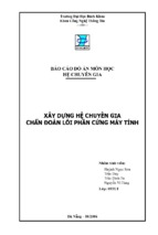
1.3 Name of Parts
1.3.1 External View
0009-2753
[3]
[2]
[6]
[7]
T-1-1
[6] Left cover
[2] Upper cover
[7] Right cover
[4] Pickup tray
IX
[5] Front cover
WW
.F
1.3.2 Cross Section View
[3] [4] [5]
[6]
0007-6027
[7]
HT
TP
:/
/W
[1] [2]
[4]
CL
[1] Rear cover
[3] Delivery tray
[5]
UB
F-1-1
.C
OM
.C
N
[1]
[12] [11] [10]
[9] [8]
F-1-2
1-3
Chapter 1
T-1-2
[1] Photosensitive drum
[8] Developing cylinder
[2] Pressure roller
[9] Pickup roller
[3] Fixing film assembly
[10] Separation pad
[4] Delivery roller
[11]Feed roller
[5] Primary charging roller
[12] Transfer charging roller
[6] Toner cartridge
HT
TP
:/
/W
WW
.F
IX
CL
UB
.C
OM
.C
N
[7] Laser scanner assembly
1-4
- Xem thêm -