Vietnam National University, Hanoi
University of Engineering and Technology
Faculty of Information Technology
A Unified View Approach to
Software Development Automation
Le Minh Duc
Doctor of Philosophy Dissertation Summary
Hanoi - 2019
Vietnam National University, Hanoi
University of Engineering and Technology
Faculty of Information Technology
A Unified View Approach to
Software Development Automation
Le Minh Duc
Supervisors: Prof. Dr. Nguyen Viet Ha
Dr. Dang Duc Hanh
Discipline:
Information Technology
Specialisation: Software Engineering
Doctor of Philosophy Dissertation Summary
Hanoi - 2019
Contents
1
2
Introduction
1
1.1
Problem Statement . . . . . . . . . . . . . . . . . . . . . . . . . . . . . . . . . . . . . . . .
1
1.2
Dissertation Structure . . . . . . . . . . . . . . . . . . . . . . . . . . . . . . . . . . . . . . .
2
State of the Art
3
2.1
Background . . . . . . . . . . . . . . . . . . . . . . . . . . . . . . . . . . . . . . . . . . . .
3
2.1.1
Model-Driven Software Engineering . . . . . . . . . . . . . . . . . . . . . . . . . . .
3
2.1.2
Domain-Specific Language . . . . . . . . . . . . . . . . . . . . . . . . . . . . . . . .
3
2.1.3
Meta-Modelling with UML/OCL . . . . . . . . . . . . . . . . . . . . . . . . . . . .
4
2.1.4
Domain-Driven Design . . . . . . . . . . . . . . . . . . . . . . . . . . . . . . . . . .
4
2.1.5
Model-View-Controller Architecture . . . . . . . . . . . . . . . . . . . . . . . . . . .
5
2.1.6
Extending MVC to Support Non-functional Requirements . . . . . . . . . . . . . . .
5
2.1.7
Object-Oriented Programming Language . . . . . . . . . . . . . . . . . . . . . . . .
5
2.1.8
Using Annotation in MBSD . . . . . . . . . . . . . . . . . . . . . . . . . . . . . . .
5
Domain-Driven Software Development with aDSL . . . . . . . . . . . . . . . . . . . . . . .
6
2.2.1
DDD with aDSL . . . . . . . . . . . . . . . . . . . . . . . . . . . . . . . . . . . . .
6
2.2.2
Behavioural Modelling with UML Activity Diagram . . . . . . . . . . . . . . . . . .
6
2.2.3
Software Module Design . . . . . . . . . . . . . . . . . . . . . . . . . . . . . . . . .
6
2.2.4
Module-Based Software Architecture . . . . . . . . . . . . . . . . . . . . . . . . . .
6
2.2
3
Unified Domain Modelling with aDSL
8
3.1
DCSL Domain . . . . . . . . . . . . . . . . . . . . . . . . . . . . . . . . . . . . . . . . . .
8
3.2
DCSL Syntax . . . . . . . . . . . . . . . . . . . . . . . . . . . . . . . . . . . . . . . . . . .
9
3.3
Static Semantics of DCSL . . . . . . . . . . . . . . . . . . . . . . . . . . . . . . . . . . . .
9
3.3.1
State Space Semantics . . . . . . . . . . . . . . . . . . . . . . . . . . . . . . . . . .
9
3.3.2
Behaviour Space Semantics . . . . . . . . . . . . . . . . . . . . . . . . . . . . . . .
10
3.3.3
Behaviour Generation for DCSL Model . . . . . . . . . . . . . . . . . . . . . . . . .
11
3.4
Dynamic Semantics of DCSL . . . . . . . . . . . . . . . . . . . . . . . . . . . . . . . . . .
11
3.5
Unified Domain Model . . . . . . . . . . . . . . . . . . . . . . . . . . . . . . . . . . . . . .
11
i
4
Module-Based Software Construction with aDSL
13
4.1
Software Characterisation . . . . . . . . . . . . . . . . . . . . . . . . . . . . . . . . . . . . .
13
4.2
Module Configuration Domain . . . . . . . . . . . . . . . . . . . . . . . . . . . . . . . . . .
13
4.3
MCCL Language Specification . . . . . . . . . . . . . . . . . . . . . . . . . . . . . . . . . .
14
4.3.1
Conceptual Model . . . . . . . . . . . . . . . . . . . . . . . . . . . . . . . . . . . .
14
4.3.2
Abstract Syntax . . . . . . . . . . . . . . . . . . . . . . . . . . . . . . . . . . . . . .
14
4.3.3
Concrete Syntax . . . . . . . . . . . . . . . . . . . . . . . . . . . . . . . . . . . . .
16
MCC Generation . . . . . . . . . . . . . . . . . . . . . . . . . . . . . . . . . . . . . . . . .
17
4.4
5
Evaluation
18
5.1
Implementation . . . . . . . . . . . . . . . . . . . . . . . . . . . . . . . . . . . . . . . . . .
18
5.2
Case Study: ProcessMan . . . . . . . . . . . . . . . . . . . . . . . . . . . . . . . . . . . .
18
5.2.1
Process Domain Model . . . . . . . . . . . . . . . . . . . . . . . . . . . . . . . . . .
19
5.2.2
Module Configuration Classes . . . . . . . . . . . . . . . . . . . . . . . . . . . . . .
19
DCSL Evaluation . . . . . . . . . . . . . . . . . . . . . . . . . . . . . . . . . . . . . . . . .
19
5.3.1
Evaluation Approach . . . . . . . . . . . . . . . . . . . . . . . . . . . . . . . . . . .
19
5.3.2
Expressiveness . . . . . . . . . . . . . . . . . . . . . . . . . . . . . . . . . . . . . .
19
5.3.3
Required Coding Level . . . . . . . . . . . . . . . . . . . . . . . . . . . . . . . . . .
20
5.3.4
Behaviour Generation . . . . . . . . . . . . . . . . . . . . . . . . . . . . . . . . . .
20
5.3.5
Performance Analysis . . . . . . . . . . . . . . . . . . . . . . . . . . . . . . . . . .
20
Evaluation of Module-Based Software Construction . . . . . . . . . . . . . . . . . . . . . . .
20
5.4.1
Method . . . . . . . . . . . . . . . . . . . . . . . . . . . . . . . . . . . . . . . . . .
20
5.4.2
M P1 : Total Generativity . . . . . . . . . . . . . . . . . . . . . . . . . . . . . . . . .
21
5.4.3
M P2 –M P4 . . . . . . . . . . . . . . . . . . . . . . . . . . . . . . . . . . . . . . . .
21
5.4.4
Analysis of MCCGen . . . . . . . . . . . . . . . . . . . . . . . . . . . . . . . . . .
22
5.3
5.4
6
Conclusion
23
6.1
Key Contributions . . . . . . . . . . . . . . . . . . . . . . . . . . . . . . . . . . . . . . . . .
23
6.2
Future Work . . . . . . . . . . . . . . . . . . . . . . . . . . . . . . . . . . . . . . . . . . . .
24
Publications
25
ii
Chapter 1
Introduction
There is no doubt that an important software engineering research area over the last two decades is what
we would generally call model-based software development (MBSD) – the idea that a software can and
should systematically be developed from abtractions, a.k.a models, of the problem domain. MBSD brings
many important benefits, including ease of problem solving and improved quality, productivity and reusability.
Perhaps a most visible software engineering development that falls under the MBSD umbrella is model-driven
software engineering (MDSE). Another more modest, but not less important, development method is domaindriven design (DDD). While the MDSE’s goal is ambitiously broad and encompassing, DDD focuses more
specifically on the problem of how to effectively use models to tackle the complexity inherent in the domain
requirements. DDD’s goal is to develop software based on domain models that not only truly describe the
domain but are technically feasible for implementation. According to Evans, object-oriented programming
language (OOPL) is especially suited for use with DDD.
The domain model, which is primarily studied under DDD and a type of model engineered in MDSE, is in
fact the basis for specifying what had been called in the language engineering community as domain-specific
language (DSL). The aim of DSL is to express the domain using concepts that are familiar to the domain
experts. A type of DSL, called annotation-based DSL (aDSL), is an application of the annotation feature of
modern OOPLs in DSL engineering. A key benefit of aDSL is that it is internal to the host OOPL and thus
does not require a separate syntax specification. This helps significantly reduce development cost and increase
ease-of-learning. In fact, simple forms of aDSL have been used quite extensively in both DDD and MDSE
communities. In DDD, annotation-based extensions of OOPLs have been used to design software frameworks
that help develop the domain model and the final software.
Our initial research started out with an MBSD-typed investigation into the problem of how to improve the
productivity of object-oriented software development using a Java-based design language for the domain model
and a software architectural model. Placing these works in the context of DDD, MDSE and aDSL allow us to
advance our research to tackle a broader and more important problem concerning the DDD method.
1.1
Problem Statement
DDD is a design method that tackles the complexity that lies at the heart of software development. However,
there are still important open issues with DDD concerning domain modelling and software development from
the domain model. First, the domain model does not define the essential structural elements and lacks support
for behavioural modelling. Second, there has been no formal study of how aDSL is used in DDD. This is despite
the fact that annotation is being used quite extensively in implementations of the method in the existing DDD
software frameworks. Third, there has been no formal study of how to construct software from the domain
model. In particular, such a study should investigate generative techniques (similar to those employed in MDSE)
that are used to automate software construction.
1
Research Aim and Contributions
In this dissertation, we address the issues mentioned in the problem statement by formally using aDSL to not
only construct an essential and unified domain model but generatively construct modular software from this
model. This dissertation makes five main contributions. The first contribution is an aDSL, named domain
class specification language (DCSL), which consists in a set of annotations that express the essential structural
constraints and the essential behaviour of a domain class. The second contribution is a unified domain (UD)
modelling approach, which uses DCSL to express both the structural and behavioural modelling elements.
We choose UML activity diagram language for behavioural modelling and discuss how the domain-specific
constructs of this language are expressed in DCSL. The third contribution is a 4-property characterisation for
the software that are constructed directly from the domain model. These properties are defined based on a
conceptual layered software model. The fourth contribution is a second aDSL, named module configuration
class language (MCCL), that is used for designing module configuration classes (MCCs) in a module-based
software architecture. The fifth contribution is a set of software tools for DCSL, MCCL and the generators
associated with these aDSLs. We implement these tools as components in a software framework, named
jDomainApp. To evaluate the contributions, we first demonstrate the practicality of our method by applying
it to a relatively complex, real-world software construction case study. We then evaluate DCSL as a design
specification language and evaluate the effectiveness of using MCCL in module-based software construction.
1.2
Dissertation Structure
This dissertation is organised into chapters that closely reflect the stated contributions. Chapter 2 systematically
presents the background knowledge concerning the related concepts, methods, techniques and tools. Chapter 3
describes our contributions concerning UD modelling. We first specify DCSL for expressing the essential
structural and behavioural features of the domain class. We then use DCSL to define unified domain model.
After that, we present a set of generic UD modelling patterns that can be applied to construct UDMs for realworld domains. Chapter 4 explains our contributions concerning module-based software construction. We first
set the software construction context by defining a software characterisation scheme. We then specify MCCL for
expressing the MCCs and present a generator for generating the MCCs. Chapter 5 presents tool support and an
evaluation of our contributions. Chapter 6 concludes the dissertation with a summary of the research problem,
the contributions that we made and the impacts that these have on advancing the DDD method. We also highlight
a number of ideas and directions for future research in this area.
2
Chapter 2
State of the Art
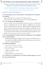
In this chapter, we present a methodological study of the literatures that are relevant to this dissertation.
Our objectives are (i) to gather authoritative guidance for and to define the foundational concepts, methods and
techniques and (ii) to identify unresolved issues concerning the DDD method that can be addressed in research.
2.1
Background
We begin in this section with a review of the relevant background concepts, methods and techniques concerning
MDSE, DDD, OOPL and aDSL.
2.1.1
Model-Driven Software Engineering
Historically, model-driven software engineering (MDSE) evolves from a general system engineering method
called model-driven engineering (MDE). MDE in turn was invented on the basis of model-driven architecture
(MDA). Since our aim in this dissertation is to study the development of software systems, we will limit our
focus to just MDSE. Kent et al. define MDA as “...an approach to IT system specification that separates the
specification of system functionality from the specification of the implementation of that functionality on a
specific technology platform”. The two types of specification mentioned in this definition are represented
by two types of model: platform-independent model (PIM) and platform-specific model (PSM). The
former represents the system functionality, while the latter the platform. MDA defines four types of model
transformations between PIM and PSM.
Kent et al. suggest further that meta-modelling be used for specifying languages. They state that languages
definitions are just models (called meta-models) with mappings defined between them. Meta-modelling can be
used to specify the abstract and concrete syntax, and the semantics of a language.
Schmidt states that MDE technologies should be developed to combine domain-specific modelling language (DSML), transformation engine and generator. DSML is a type of domain-specific language (DSL) that
is defined through meta-modelling. More recently, Brambilla et al define MDSE as “...a methodology for applying the advantages of modelling to software engineering activities”. The key concepts that MDSE entails are
models and transformations (or “manipulation operations” on models). MDSE can also be integrated into agile,
domain-driven design (DDD) and test-driven development processes. Within the scope of this dissertation, we
are interested in the integration capability of MDSE into DDD.
2.1.2
Domain-Specific Language
DSL is a software language that is specifically designed for expressing the requirements of a problem domain,
using the conceptual notation suitable for the domain. DSLs can be classified based on domain or on the
relationship with the target (a.k.a host) programming language. From the domain’s perspective, DSLs can be
3
classified as being either vertical or horizontal DSL. Regarding to the relationship with the host language, DSLs
can be classified as being internal or external.
2.1.3
Meta-Modelling with UML/OCL
In fact, meta-modelling is a modelling approach that is applied to defining any software language, including both
DSLs and general purpose languages (e.g. Java, C# and the like). In meta-modelling, a language specification
consists in three meta-models and the relations between them. The first meta-model describes the abstract syntax
and is called abstract syntax meta-model (ASM). The second meta-model describes the concrete syntax and
is called concrete syntax meta-model (CSM). The third meta-model describes the semantics and is called
semantic domain meta-model (SDM). A de facto meta-modelling language is Unifield Modelling Language
(UML). UML consists in a family of languages, one of which is UML class diagram. This language, which we
will refer to in this dissertation as class modelling language, is made more precise when combined with the
Object Constraint Language (OCL). We call the combined language UML/OCL.
The Essential ASM of UML. The essential ASM for UML consists of the following meta-concepts: Class,
Attribute, Association, Association End, Operation, Parameter, Association Class and Generalisation. This
ASM suffices for our research purpose in this dissertation.
Approaches for Specifying SDM. Kleppe states four general approaches to defining the SDM of a language:
denotational, translational, pragmatic and operational. Kleppe’s view of the SDM amounts to dynamic
semantics. From the programming language’s perspective, there is also a static semantics of a language, which
does not rely on the run-time. This semantics describes the well-formedness of the language constructs and
thus can be checked at compile-time.
2.1.4
Domain-Driven Design
The general goal of domain-driven design (DDD) is to develop software iteratively around a realistic model of
the application domain, which both thoroughly captures the domain requirements and is technically feasible for
implementation. In this dissertation, we will use DDD to refer specifically to object-oriented DDD. Domain
modelling is concerned with building a domain model for each subject area of interest of a domain. DDD
considers domain model to be the core (or “heart”) of software, which is where the complexity lies.
DDD Patterns. The DDD method provides a set of seven design patterns that address these two main
problem types: (i) constructing the domain model (4 patterns) and (ii) managing the life cycle of domain
objects (3 patterns). The four patterns of the first problem type are: entities, value objects, services and
modules. The three patterns of the second problem type are: aggregates, factories and repositories. In
this dissertation, the term “DDD patterns” will mean to include only the four patterns of the first problem type
and the pattern aggregates. We argue that the other two patterns are generic software design patterns and, as
such, are not specific to DDD.
DDD with DSL. The idea of combining DDD and DSL to raise the level of abstraction of the target code
model has been advocated by both the DDD’s author and others. However, they do not discuss any specific
solutions for the idea. Other works on combining DDD and DSL (e.g. Sculptor) focus only on structural
modelling and use an external rather than an internal DSL.
4
2.1.5
Model-View-Controller Architecture
To construct DDD software from the domain model requires an architectural model that conforms to the generic
layered architecture. A key requirement of such model is that it positions the domain model at the core layer,
isolating it from the user interface and other layers. Evans suggests that the Model-View-Controller (MVC)
architecture model is one such model. Technically, MVC is considered in to be one of several so-called agentbased design architectures. The main benefit of MVC is that it helps make software developed in it inherently
modular and thus easier to maintain. Software that are designed in MVC consists of three components: model,
view and controller. The internal design of each of the three components is maintained independently with
minimum impact (if any) on the other two components.
2.1.6
Extending MVC to Support Non-functional Requirements
Unfortunately, the Evans’s domain modelling method only focuses on functional requirement. If we were to
apply DDD to develop real-world software, it is imperative that the adopted software architecture supports Nonfunctional requirements (NFRs). Three existing works have argued that the MVC architecture is extendable to
support NFRs.
2.1.7
Object-Oriented Programming Language
In his book, Evans uses Java to demonstrate the DDD method. We argue that because Java and another, also
very popular, OOPL named C# share a number of core features, we will generalise these features to form what
we term in this dissertation a “generalised” OOPL. The UML-based ASM of OOPL includes the following core
meta-concepts (supported by boh Java and C#): Class, Field, Annotation, Property, Generalisation,
Method and Parameter.
Mapping OOPL to UML/OCL. We conclude our review of OOPL with a brief discussion of the mapping
between this language and UML/OCL. We call this mapping meta-mapping, because it maps the ASMs of the
two languages. In practice, this mapping is essential for transforming a UML/OCL design into the code model
of a target OOPL (e.g. Java and C#).
2.1.8
Using Annotation in MBSD
After more than a decade since OOPL was introduced, three noticable methodological developments concerning
the use of annotation in MBSD began to form. The first development is attribute-oriented programming
(AtOP). Another development revolves round behaviour interface specification language (BISL). The third
and more recent development is annotation-based DSL.
Of interest to our dissertation are BISLs that (i) express functional behaviour properties for object oriented
source code and (ii) use some form of annotation to structure the specification. BISLs can be characterised by
the properties that they express and by the software development artefacts that they describe. The behaviour
properties are concerned with the transformation from the pre-condition state to the post-condition state of a
method and the consistency criteria (invariant) of class. Two popular BISLs supporting these properties are
Java Modelling Language (JML) and Spec#.
5
Annotation-Based DSL (aDSL) is an application of the annotation feature of modern OOPLs in DSL
engineering. The name “annotation-based DSL” has been coined and studied only recently by Nosal et al. A few
years earlier, however, Fowler and White had classified this type of language as “fragmentary, internal DSL”.
2.2
Domain-Driven Software Development with aDSL
Recently, we observe that a current trend in DDD is to utilise the domain model for software construction. Given
a domain model, other parts of software, including graphical user interface (GUI), are constructed directly from
it. Further, this construction is automated to a certain extent.
2.2.1
DDD with aDSL
Exiting DDD works mentioned above have several limitations. First, they do not formalise their annotation
extensions into a language. Second, their extensions, though include many annotations, do not identify those
that express the minimal (absolutely essential) annotations. Third, they do not investigate what DSLs are needed
to build a complete software model and how to engineer such DSLs.
2.2.2
Behavioural Modelling with UML Activity Diagram
Evans does not explicitly consider behavioural modelling as part of DDD. This shortcoming remains, inspite
of the fact that the method considers object behaviour as an essential part of the domain model and that UML
interaction diagrams would be used to model this behaviour. In UML (§13.2.1), interaction diagrams (such
as sequence diagram) are only one of three main diagram types that are used to model the system behaviour.
The other two types are state machine (§14) and activity diagram (§15, 16). We will focus in this dissertation
on the use of UML activity diagram for behavioural modelling. We apply the meta-modelling approach with
UML/OCL (see Section 2.1.3) to define an essential ASM of the activity modelling language.
2.2.3
Software Module Design
Traditionally, in object oriented software design, it is well understood that large and complex software requires
a modular structure. According to Meyer, software module is a self-contained decomposition unit of a software.
For large and complex software that is developed using the DDD method, the domain model needs to be designed
in such a way that can easily cope with the growth in size and complexity. Although the existing works in DDD
support domain module, they do not address how to use it to form software module. Further, they lack a method
for software module development. Not only that, they do not characterise the software that is developed from
the domain model.
2.2.4
Module-Based Software Architecture
In this dissertation, we adopted a module-based software architecture (MOSA), which we developed in
previous works, for software development in DDD. We chose MOSA because it was developed based on the
MVC architecture and specifically for domain-driven software development. MOSA is built upon two key
concepts: MVC-based module class and module containment tree.
6
Definition 2.1. Module class is a structured class that describes the structure of modules in terms of three MVC
components: model (a domain class), a view class and a controller class. Given a domain class C, the view
and controller classes are the parameterised classes ViewhT → C i and ControllerhT → C i (resp.); where
ViewhT i and ControllerhT i are two library template classes, T is the template parameter.
Definition 2.2. Given two domain classes C and D, a module M = ModuleC (called composite module)
contains another module N = ModuleD (called child module), if
– C participates in a binary association (denoted by A) with D.
– C is at the one end (if A is one-many), at the mandatory one end (if A is one-one) or at either end (if
otherwise).
– Exists a subset of N ’s state scope, called containment scope, that satisfies M ’s specification.
Definition 2.3. Containment tree is a rooted tree that has the following structure:
– Root node is a composite module (called the root module). Other nodes are modules that are contained
directly or indirectly by the root module. We call these the descendant modules.
– Tree edge from a parent node to a child node represents a module containment.
Module Configuration Method
We view module configuration at two levels. At the module level, a configuration specifies the model, view
and controller components that make up a module class. At the component level, the configuration specifies
properties of each of the three components.
Microservices Architecture
Coincidentally, the MOSA architecture was conceived and proposed at around the same time as the emergence
of a variant of the service-oriented architecture (SOA) named microservices architecture (MSA). According to
Lewis and Fowler, MSA is “. . . an approach to developing a single application as a suite of small services, each
running in its own process and communicating with lightweight mechanisms, often an HTTP resource API”. We
argue that MOSA is similar to MSA in the following seven (out of nine) fundamental characteristics of MSA that
were identified by Lewis and Fowler: component-based, “smart” components, domain-driven decomposition
strategy, product not the project, automation, failure isolation and evolutionary design. However, MSA differs
from MOSA in three aspects: origin, extent of the relationship to DDD and message exchange protocol between
components.
7
Chapter 3
Unified Domain Modelling with aDSL
In this chapter, we describe our first two contributions concerning unified domain (UD) modelling. We first
specify a horizontal aDSL, called DCSL, for expressing the essential structural and behavioural features of the
domain class. We then use DCSL to define unified domain model (UDM). In this, we present a set of generic
UD modelling patterns that can be used to construct UDMs for real-world problem domains. The content of
this chapter has been published in a conference paper (numbered 1) and a journal paper (numbered 4).
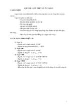
3.1
DCSL Domain
The DCSL’s domain is a
horizontal (technical) domain that is described in
terms of the OOPL metaconcepts and a number of
essential state space constraints and essential behaviours that operate under these constraints. We
identified 11 types of constraints that are essential to
the conception of domain
class. We name these constraints as follow: object
mutability (OM), field mutability (FM), field optionality (FO), field length (FL),
field uniqueness (FU), id
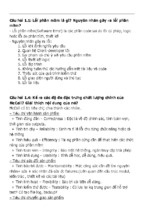
Figure 3.1: The abstract syntax model of DCSL.
field (IF), min field value (YV), max field value (XV), auto field (TF), min number of linked objects (YL)
and max number of linked objects (XL). We will use the term state space constraints to refer to the constraints,
and the term domain state space (or state space for short) to refer to the state space restricted by them.
An essential behaviour type specifies a pattern of behaviour that is essential for each domain class baring
the essential state space constraints stated above. We analysed the state space constraints in the context of three
core operation types: creator, mutator and observer. We specialised these types for the constraints to yield 11
essential behaviour types: RequiredConstructor, ObjectFormConstructor, AutoAttributeValueGen,
LinkCountGetter, LinkCountSetter, LinkAdder, LinkAdderNew, LinkRemover, LinkUpdater, Getter
and Setter. We say that the behaviour types form the behaviour space of domain class.
8
3.2
DCSL Syntax
Definition 3.1. A meta-attribute AT is an annotation whose properties structurally describe the non-annotation
meta-concepts T to which it is attached.
Figure 3.1 shows an UML/OCL model for the DCSL’s ASM. It consists of five core meta-attributes, three
auxiliary annotations and an enum named OptType. The five meta-attributes are DClass{Class} , DAttr{Field} ,
DAssoc{Field} , DOpt{Method} and AttrRef{Method, Parameter} . The three auxiliary annotations are Associate,
AssocType and AssocEndType. The enum OptType captures the type names of the 11 essential behaviour
types. The two meta-attributes DClass and DAttr together possess properties that directly model the first nine
state space constraints. The other two constraints (YL and XL) are modelled by the third meta-attribute named
DAssoc. The remaining two meta-attributes (DOpt and AttrRef) model the essential behaviour of Method.
Definition 3.2. Given a DCSL model M . An element c : Class ∈ M is a domain class if c is assigned with a
DClass element. An element f : Field ∈ M is a domain field if f is assigned with a DAttr element. A domain
field f ∈ M is an associative field if f is assigned with a DAssoc element. An element m : Method ∈ M is
called a domain method if m is assigned with a DOpt element.
3.3
Static Semantics of DCSL
We define a set of rules that precisely describe the state space constraints and the behaviour types that are
captured by the DCSL’s meta-attributes. These rules form the core static semantics of DCSL. We divide the
static semantic rules into two groups: state space semantics and behaviour space semantics.
3.3.1
State Space Semantics
The state space semantic rules are constraints on the ASM and, thus, we use OCL invariant to precisely define
these rules. The benefit of using invariant is that it allows us to specify exactly the structural violation of the
constraint, which occurs if and only if the invariant is evaluated to false. The OCL invariant is defined on an
OOPL meta-concept and has the following general form:
φ implies E
where E is an OCL expression on the ASM structure that must conditionally be true in order for the constraint
to be satisfied; φ is the condition upon which E is evaluated. It is defined based on some characteristic C of the
meta-concept:
φ=
true,
if C is in effect
false,
if C is not in effect.
Note that when φ = true then E is evaluated and the result equates the constraint’s satisfaction. Otherwise,
E does not need to be evaluated (can be either true or false). We divide the OCL constraints into two groups:
(i) well-formedness constraints and (ii) state space constraints.
Well-formedness Rules. An important well-formedness rule is rule WF4, which we call generalisation
constraint. This constraint, when combined with the relevant generalisation rules enforced by OOPL, help
9
ensure that the state space constraints are preserved through inheritance. More specifically, rule WF4 is applied
to all the overridden methods that reference a domain field of an ancestor class in the inheritance hierarchy.
Informally, this rule states that each overridden method must be assigned with an DAttr that preserves the
DAttr of the referenced domain field.
Boolean State Space Constraints. The boolean state space constraints include OM, FM, FO, FU, IF
and TF. These constraints are expressed by the following Boolean-typed annotation properties in DCSL:
DClass.mutable and DAttr.mutable, optional, unique, id, auto. Each constraint has the following (more
specialised) form:
X.P implies E
where: φ = X.P, denotes value of the boolean property P of some model element X (X can be a navigation
sequence through the association links between model elements e1 .e2 . . . en ); E is defined as before.
Non-Boolean State Space Constraints. The non-boolean constraints include FL, YV, XV, YL and
XL. These are expressed by the following annotation properties in DCSL: DAttr.length, min, max and
Associate.cardMin, cardMax. Each constraint has the following (more specialised) form:
X.P op v implies E
where: φ = X.P op v, denotes an OCL expression that compares, using operator op, the value of some
property X.P to some value v; E is defined as before.
3.3.2
Behaviour Space Semantics
The behaviour space semantic rules are designed to make precise the static semantics of the behaviour types.
The formalism that we use is based directly on the OOPL’s meta-concepts and, thus, has an added benefit that
it can be implemented easily in a target OOPL. We define the semantic rules based on a structural mapping
between the state space and the behaviour space. This mapping consists of a set of rules, called structural
mapping rules, that map elements of meta-attribute assignments (in the state space) to the behaviour elements
of the behavioural types. Table 3.1 lists the structural mapping rules for the different OptTypes in DCSL
Table 3.1: The core structural mapping rules
No
1
2
3
4
5
6
Property
auto
type
auto
type
optional
mutable
auto
type
type
SSEP(N)s
DAttr
DAssoc
Stateful func.
Stateful func.
Property
isNotAuto
–
–
isNotCollectionType
–
–
isNotAuto
–
–
isNotCollectionType
–
–
isNotOptional
–
–
isMutable
–
–
isAuto
unassign
–
ascType
isOneManyAsc
endType
isOneEnd
ascType
isOneOneAsc
isCollectionType
isDomainType
10
Property
BSEPs
DOpt
Stateful func.
type
isObjectFormConstructorType
type
isRequiredConstructorType
type
type
type
type
type
type
type
type
type
isSetterType
isAutoAttributeValueGenType
isLinkAdderNewType
isLinkAdderType
isLinkUpdaterType
isLinkRemoverType
isLinkCountGetterType
isLinkCountSetterType
isLinkAdderNewType
3.3.3
Behaviour Generation for DCSL Model
We show in Alg. 3.1 a programmatic technique that uses the static semantics described in the previous subsections
to automatically generate the behaviour specification of the domain methods.
Alg.3.1 BSpaceGen
Input: c: a domain class whose state space is specified
Output: c is updated with domain method specification (of the behaviour space)
// create constructors
1 FU ⇐ set of non-auto, non-collection-typed domain fields of c
2 FR ⇐ set of non-optional domain fields of c
3 create in c object-form-constructor c1 (u1 , . . . , um ) (uj ∈ FU ) // rule 1
4 create/update in c required-constructor c2 (r1 , . . . , rp ) (rk ∈ FR ) // rule 2
// create other methods
5 for all domain field f of c do
6 create in c getter for f
7 if f is mutable then create in c setter for f end if // rule 3
8 if def(DAssoc(f )) then
9
if isOneManyAsc(DAssoc(f )) ∧ isOneEnd(DAssoc(f )) then create in c link-related methods for f // rule 5
10
else if isOneOneAsc(DAssoc(f )) then create in c link-adder-new for f end if // rule 6
11 if isAuto(DAttr(f )) ∧ undef(DAssoc(f )) then create in c auto-attribute-value-gen for f end if // rule 4
Theorem 3.1. Behaviour Generation
The input domain class updated by Alg 3.1 is behaviour essential.
Theorem 3.2. Complexity
The worst-case time complexity of Alg 3.1 is linear in number of domain fields of the input domain class.
3.4
Dynamic Semantics of DCSL
In principle, the dynamic semantics of DCSL is derived from the dynamic semantics of the host OOPL,
augmented with the semantics of the DCSL’s meta-attributes. More technically, that semantics describes what
happens when a DCSL model, written as a program in an OOPL, is executed. We will discuss the dynamic
semantics of DCSL under the headings of its three terms (see Definition 3.2).
Domain Class and Method. Domain Class and Domain Method do not affect the dynamic semantics of
Class and Method (resp.).
Domain Field. We observe that a subset of the properties of Domain Field, which are defined in two
meta-attributes DAttr and DAssoc, only have the static semantics explained in Section 3.3. Other properties
carry dynamic semantics. These properties are: (i) DAttr.optional, length, unique, min, max, cardMin,
cardMax and (ii) DAssoc.cardMin, cardMax.
3.5
Unified Domain Model
We use DCSL to construct a unified domain model (UDM). We call the process for constructing a UDM UD
modelling. The term ‘unified’ in UDM refers to a unique representation scheme that we propose, which merges
the class modelling structure and the state-specific activity modelling structure into a unified class model. The
state-specific structure includes activity class and activity node, but excludes activity edge. We first define the
unified class model and then explain how this model is expressed as UDM in DCSL.
11
Definition 3.3. A unified class model is a domain model whose elements belong to the following types:
• activity class: a domain class that represents the activity.
• entity class: a domain class that represents the type of an object node. This class models an entity type.
• control class: captures the domain-specific state of a control node. A control class that represents a
control node is named after the node type; e.g. decision class, join class and so on.
• activity-specific association: an association between each of following class pairs: (i) activity class and
a merge class; (ii) activity class and a fork class; (iii) a merge (resp. fork) class and an entity class that
represents the object node of an action node connected to the merge (resp. fork) node; (iv) activity class
and an entity class that does not represent the object node of an action node connected to either a merge
or fork node.
We will collectively refer to the entity and control classes as component classes.
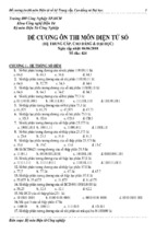
Figure 3.2: The decisional pattern form (top left) and an application to the enrolment management activity.
Definition 3.4. A unified domain model (UDM) is a DCSL model that realises a unified class model as follows:
– a domain class ca (called the activity domain class) to realise the activity class.
– the domain classes c1 , . . . , cn to realise the component classes.
– let ci1 , . . . , cik ∈ {c1 , . . . , cn } realise the non-decision and non-join component classes, then ca , ci1 , . . . , cik
contain associative fields that realise the association ends of the activity-specific associations.
UD Modelling Patterns. To demonstrate the practicality of UDM we define five UD modelling patterns.
We name these patterns (sequential, decisional, forked, joined and merged) after the five primitive activity flows
of the activity modelling language. For example, we show in Figure 3.2 the form of the decisional pattern.
12
Chapter 4
Module-Based Software Construction with aDSL
In this chapter, we explain our contributions concerning module-based software construction. We first set
the software construction context by defining a software characterisation scheme. We then specify another
horizontal aDSL, called MCCL, for expressing the module configuration classes (MCCs). We also discuss
a generator for the MCCs. The software characterisation scheme has been published in a journal paper
(numbered 4). MCCL and the associated generator have been published in a conference paper (numbered 3)
and conditionally accepted in another journal (numbered 5).
4.1
Software Characterisation
We proposed four properties that characterise the software developed in a DDD method. Two of these properties
(instance-based GUI and model reflectivity) arise from the need to construct software from the UDM. The other
two properties (modularity and generativity) were derived from well-known design properties.
Instance-based GUI is the extent to which the software uses a GUI to allow a user to observe and work on
instances of the UDM. Model reflectivity is the extent to which the GUI faithfully presents the UDM and its
structure. This property is central to the functionality of the software GUI.
Modularity is the extent to which a software development method possesses the following five criteria:
decomposability, composability, understandability, continuity and protection. We adapt these high-level criteria
to define modularity for software constructed with DDD as follows: Decomposability is the extent to which the
domain classes of the UDM and the modules are constructed in the incremental, top-down fashion. Composability is the extent to which packaging domain classes into modules helps ease the task of combining them
to form a new software. Understandability is the extent to which the module structure helps describe what a
module is. Continuity is the extent of separation of concerns supported by the module structure. Protection
is the extent to which the domain class behaviour and the user actions concerning the performance of this
behaviour are encapsulated in a module.
Generativity refers to the extent to which the software is automatically generated from the UDM, leveraging
the capabilities of the target OOPL platform. We define generativity in terms of view generativity, module
generativity and software generativity.
4.2
Module Configuration Domain
We consider the domain’s scope to include the module configuration method of the previous work (presented in
Section 2.2.4) and the three enhancements to this method. The first enhancement is to create one master module
configuration. The second enhancement is to introduce the concept of configured containment tree. The third
enhancement is to support the customisation of descendant module configuration in a containment tree.
13
4.3
4.3.1
MCCL Language Specification
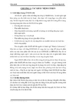
Conceptual Model
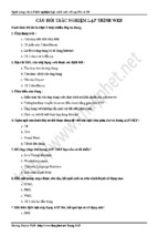
Figure 4.1 shows the UML class diagram of the conceptual model (CM) of the MCCL’s domain. It consists of
two parts: (i) ModuleConfig and the component configurations and (ii) Tree representing containment trees.
Figure 4.1: The CM of MCCL.
Well-formedness Rules We use OCL invariant to precisely express the well-formedness rules of the CM. We
group the rules by the meta-concepts of the CM to which they are applied. The rule definitions use a number
of shared (library) rules. Syntactically, some rules use DCSL to express constraints on certain meta-concepts’
attributes. This is is more compact and intuitive.
4.3.2
Abstract Syntax
Our main objective is to construct an ASM from the CM by transformation, so that the ASM takes the annotationbased form, suitable for being embedded into a host OOPL. Furthermore, we will strive for a compact ASM that
uses a small set of annotations. To achieve this requires two steps. First, we transform CM into another model,
called CMT , that is compact and suitable for annotation-based representation. Second, we transform CMT into
the actual annotation-based ASM.
CMT : A Compact and Annotation-Friendly Model. Figure 4.2 (A) shows the UML class model of CMT .
The detailed design of the key classes are shown in Figure 4.2 (B). The tree structure Tree-Node-RootNodeEdge of the original CM is replaced by the structure CTree-CEdge in CMT . This new tree representation is
more compact and fits naturally with the idea of the configured containment tree.
14
Figure 4.2: (A-shaded area) The transformed CM (CMT );
(B-remainder) Detailed design of the key classes of CMT .
The Annotation-Based ASM. Although CMT
is suitable for OOPL’s representation, it is still not
yet natively in that form. Figure 4.3 shows the
UML class model of the ASM. In this, the classes
in CMT are transformed into annotations of the
same name. Each domain field is transformed into
an annotation property. The annotations are depicted in the figure as grey-coloured boxes. A
key structural difference between ASM and CMT
is the addition of two annotation attachments:
ModuleDesc to Class and AttributeDesc to
Field.
A ModuleDesc attachment defines an
MCC because it describes the instantiation of a
Figure 4.3: The annotation-based ASM of MCCL.
ModuleDesc object together with objects of the annotations that are referenced directly and indirectly by
ModuleDesc. The association between Class and Field helps realise the composite association between
ViewDesc and AttributeDesc.
Together, the above features lead us to the following definitions of MCC and MCC model.
Definition 4.1. An MCC is a class assigned with a suitable ModuleDesc, that defines the configuration of a
module class owning a domain class in the UDM. Further, the MCC’s body consists of a set of fields that are
assigned with suitable AttributeDescs. These fields realise the view fields. Exactly one of these fields, called
the title data field, has its AttributeDesc defines the configuration of the title of the module’s view. Other
fields have the same declarations as the domain fields of the domain class and have their AttributeDescs
define the view-specific configuration of these domain fields.
We say that a view field reflects the corresponding domain field. To ease discussion, we will say that the
MCC of a module class owns its domain class.
15
Definition 4.2. An MCC model w.r.t a UDM is a model that conforms to MCCL and consists in a set of MCCs,
each of which is an MCC of an owner module of a domain class in the UDM.
4.3.3
Concrete Syntax
Because MCCL is embedded into OOPL, it is natural to consider the OOPL’s textual syntax as the concrete
syntax of MCCL. From the perspective of concrete syntax meta-modelling approach, the CSM of such textual
syntax is derived from that of OOPL. Further, the core structure of the CSM model is mapped to the ASM. In
addition to this core structure, the CSM contains meta-concepts that describe the structure of the BNF grammar
rules. The textual syntaxes of Java and C# are both described using this grammar. In this dissertation, we will
adopt the Java textual syntax as the concrete syntax of MCCL. For example, Listing 4.1 shows the MCC of
ModuleStudent
Listing 4.1: The MCC of ModuleStudent
1
2
3
4
5
6
7
8
9
10
11
12
13
14
15
16
17
18
19
20
21
22
@ ModuleDesc ( name = " ModuleStudent " ,
modelDesc = @ ModelDesc ( model = Student . class ) ,
viewDesc = @ ViewDesc ( formTitle = " Manage Students " , imageIcon = " student . jpg " ,
view = View . class , parentMenu = RegionName . Tools , topX =0.5 , topY =0.0) ,
controllerDesc = @ ControllerDesc ( controller = Controller . class ,
openPolicy = OpenPolicy . I_C ) ,
containmentTree = @CTree ( root = Student . class ,
stateScope ={ " id " , " name " , " modules " }) )
public class ModuleStudent {
@ AttributeDesc ( label = " Student " )
private String title ;
@ AttributeDesc ( label = " Id " , type = JTextField . class , alignX = AlignmentX . Center )
private int id ;
@ AttributeDesc ( label = " Full name " , type = JTextField . class )
private String name ;
@ AttributeDesc ( label = " Needs help ? " , type = JBooleanField . class )
private boolean helpReq ;
@ AttributeDesc ( label = " Enrols Into " , type = JListField . class
, ref = @Select ( clazz = CourseModule . class , attributes ={ " name " }) ,
width =100 , height =5)
private Set < CourseModule > modules ;
}
Listing 4.2 shows a partial MCC of ModuleEnrolmentMgmt that contains just the containment tree. This
MCC contains a customisation of the descendant module typed ModuleStudent.
Listing 4.2: The containment tree of ModuleEnrolmentMgmt
1
2
3
4
5
6
7
8
@ ModuleDesc ( name = " ModuleEnrolmentMgmt " ,
// other configuration elements ( omitted )
containmentTree = @CTree ( root = EnrolmentMgmt . class ,
edges ={ // enrolmentmgmt -> student
@CEdge ( parent = EnrolmentMgmt . class , child = Student . class ,
scopeDesc = @ ScopeDesc (
stateScope ={ " id " , " name " , " helpRequested " , " modules " } ,
// custom configuration for ModuleStudent
16
- Xem thêm -