Mô tả:
ADVANCED MANUFACTURING
ENGINEERING
7: Machining Processes
December 2016
Material removal mechanisms
• Cutting: machining allowance is removed in the form of
visible chips.
Cutting
2
Material removal mechanisms
• Abrasion: machining allowance is removed in the form
of minute and invisible chips by hard, tiny, randomly
oriented abrasive grit (bonded or loose) of indefinite
number and shape.
Abrasion
3
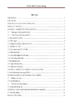
Material removal mechanisms
• Erosion: machining allowance is removed in the form of
successive surface layers as a result of dissolution,
melting and vaporization of the material being machined.
Schematic of laser cutting test setup, Shyha et al 2013
4
Classification of cutting processes
Machining by Cutting
Single
point
Turning
Boring
Shaping
Planing
Classification of cutting processes based on number
of cutting points/edges
Multi point
Drilling
Reaming
Milling
Broaching
Sawing
Filing
5
Machining by cutting
• The tool is penetrated into the w.p by a depth of cut.
• Cutting tools have definite number of cutting edges of a known
geometry.
• The machining allowance is removed in the form of visible
chips.
• The shape of the workpiece produced depends on the tool and
workpiece relative motions.
Chip
Cutting speed
Depth of cut
Tool
Cut surface
Workpiece
6
General aspects of machining technology
7
Machining productivity
• Machining productivity can be raised using the following:
• High machining speeds
• High feed rates
• Multiple cutting tools
• Stacking multiple parts
• Minimization of the secondary (noncutting) time
• Automatic feeding and tool changing mechanisms
• High power densities
8
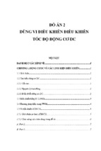
Drilling of composites
Fishbone diagram detailing factors affecting the drilling of CFRP
(Shyha, 2010)
9
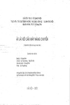
Lathe operations
• Turning means that the part is rotating while it is being
machined.
(mm/rev)
(mm)
Centre lathe
Terminology used in a turning operation on a lathe,
where f is the feed (in mm/rev) and d is the depth of cut.
10
Lathe operations
• Lathes are employed for:
• turning external cylindrical,
• tapered, and contour surfaces,
• boring cylindrical and tapered holes,
• cutting external and internal threads,
• knurling,
• centring, drilling, counter-boring, countersinking,
• spot facing,
• reaming of holes,
• cutting off, and other operations.
11
Lathe operations and tools
Cylindrical
turning
Taper turning
Facing of a WP with a facing tool while the WP
is:clamped by a half centre
mounted in a
chuck
12
Lathe operations and tools
Finish turning with a
4a. board-nose finishing tool
4b. straight finishing tool
with nose radius
Necking or recessing with a:
5a. recessing tool
5b. wide recessing tool
13
Lathe operations and tools
Parting off with a parting-off tool
Boring of cylindrical hole
8a. External threading
8b. Internal threading
14
Lathe operations and tools
Drilling with a twist drill
9a. Drilling
9b. Enlarging
10. Face
grooving
11. Profiling
12. Turning and external
grooving
15
Lathe operations and tools
13. Cutting with a form tool
14. Boring and internal
grooving
15. Knurling
16
Turning tools
N
df
do
d
f
17
Methods of taper turning
• Tapers can be manufactured on the engine lathes by:
a) rotating the compound rest to a required angle α. The
tool is fed manually by rotating handle (1). This method
is used for turning short internal and external tapers
with large taper angles, while the work is held in a
chuck and a straight turning tool is used.
18
Methods of taper turning
b)
c)
using a straight-edge
broad-nose tool. The tool
of width that exceeds the
taper being turned is crossfed. The work is held in a
chuck or clamped on a
faceplate.
using a taper-turning
attachment. This is best
suited for long tapered
work. The cross slide (1) is
disengaged from the cross
feed screw and is linked
through the tie (2) to the
slide (3).
(c)
19
Holding workpieces on lathe
WP fixation on an engine lathe depends mainly upon the
geometrical features of the WP and the precision
required. The WP can be held between centres, on a
mandrel, in a chuck, or on a faceplate.
1. Holding the WP
between
centres. It is an accurate
Plate
Driving dog
method for clamping a long WP which is rotating at
high speed.
Workpiece
Holding the work between centres
20
- Xem thêm -