Tóm tắt luận án Tiến Sĩ chuyên ngành vật liệu biến hóa
MINISTRY OF EDUCATION
VIETNAM ACADEMY
AND TRAINING
OF SCIENCE AND TECHNOLOGY
GRADUATE UNIVERSITY SCIENCE AND TECHNOLOGY
……..….***…………
PHAM THI TRANG
INVESTIGATION ON CONTROLLING THE RESONANCE
FREQUENCY AND THE RESONANCE AMPLITUDE OF
METAMATERIALS
Major: Electronic Materials
Code : 62.44.01.23
SUMMARY OF DOCTORAL THESIS
IN MATERIAL SCIENCE
Ha noi – 2017
The thesis has been completed at: Institute of Materials Science Vietnam Academy of Science and Technology.
Science supervisors: 1. Assoc. Prof., Dr. Vu Dinh Lam
2. Assoc. Prof., Dr. Le Van Hong
Reviewer 1: Assoc. Prof., Dr. Trinh Xuan Hoang
Reviewer 2: Assoc. Prof., Dr. Nguyen Minh Thuy
Reviewer 3: Assoc. Prof., Dr.Sc. Pham Van Hoi
The thesis was defended at National level Council of Thesis Assessment held at
Graduate University of Science and Technology - Vietnam Academy of Science and
Technology at on
, 2017.
Thesis can be further referred at:
- The Library of Graduate University of Science and Technology
- National Library of Vietnam
INTRODUCTION
In this day and age, the scientific and technological revolutions of
researching new materials are proceeding remarkably worldwide. Researching
and seeking new materials which are better, cheaper replacing traditional ones
have become a vital need. Moreover, this also creates materials owning new
properties, compared with traditional materials in realistic application.
Metamaterials are the materials which have artificial structure, formed by
arranging and managing the order of unit cells. Shapes and sizes of unit cells play
the role as “atoms” in traditional materials. Properties of metamaterials can be
changed with shape, composition, and order of unit cells.
There are many methods of researching into metamaterials, MPA is one of
the most considerable. This material was put forward and proved firstly in 2008
by Landy and his partners. Landy proved metamaterials can entirely absorb
electromagnetic wave energy and does not reflect. Metamaterials
electromagnetic absorber have many advantages, they are thin, easy to be made,
cheap, easily controlled, especially controlled by peripheral influences.
Numerous MPAs are proposed and researched with the exploitation of structural
artificiality, in order to search for the simple structure, possessing large working
frequency band to apply in reality, such as medical, science devices, energy
battery, invisible cloaking [4]. Furthermore, materials are really potential in other
aspects like frequency filter, resonance, antenna and biological sensor. Basing on
interesting and well – applied properties of metamaterials, it is worth every
scientist of concern all around the world. Metamaterials, in general, operate with
the bedrock is existence of magnetic and electromagnetic resonance when
interact with magnetic and electromagnetic elements of electromagnetic wave
radiating. However, resonant properties usually occur in the range of narrow
frequency band and depend on polarization of electromagnetic wave. Therefore,
before putting metamaterials into reak applications, it is necessary to solve a
number of problems: seeking materials which have simple structure, is easy to be
manufactured deploy in applications and not up to electromagnetic wave
polarization; large working frequency band materials and electromagnetic wave
isotropic receiving materials are of broad interest [5].
In the aspect of a researching group at Institute of Materials Science, fellow
Do Thanh Viet successfully defended his PhD thesis about electromagnetic
entirely absorbing materials in 2015. His thesis has concentrated on researching
to maximize the capability of structure of structure and widening working
1
frequency band of electromagnetic absorbing materials, based on cut wire pair
structure and ring structure in the range of GHz frequency. Nevertheless,
structures researched by PhD Do Thanh Viet only absorb electromagnetic wave
in one direction, not in reverse one. Meanwhile, fellow Nguyen Thi Hien
successfully defended her PhD thesis in the early of 2016 about materials which
refractive index is negative. This thesis focused on capability of widening
working frequency band by using Hybridization plasmon effect. In this effect,
she researched interaction (exterior) among structural layers’s impacts on
properties of materials.
In this thesis, fellows focused on two chief contents below:
i)
ii)
Widening working frequency band of metamaterials by using internal
interaction in structure. Particularly, researching the impact of dielectric
layer, the impact of structural asymmetrical on widening of negative
permeability range of materials.
Searching for metamaterials which have isotropic absorbing structure,
do not depend on electromagnetic wave polarization.
For these reasons, the thesis aims to design and manufacture metamaterials
which:
i)
ii)
Have simple structure, wide working frequency band.
Highly symmetrical structure, absorb isotropic electromagnetic wave.
Objects of research are metamaterials absorbing electromagnetic wave.
Scientific and realistic significance of the thesis: Thesis is a basic work
of research. Researches solve problems like widening working frequency band
of metamaterials with simple, easy to be made structure. Besides, thesis has
successfully found out metamaterials which have electromagnetic isotropic
absorbing structure, do not depend on polarization of electromagnetic wave
working in GHz frequency range. Similarly important is that this is the precursor
of following researches at high frequency range, further is completely controlling
technology of manufacturing metamaterials which operate in infrared and visible
frequency range, with many applications in reality.
The thesis is divided into 4 chapters:
Chapter 1: Overview of metamaterials.
Chapter 2: Method of research.
2
Chapter 3: Impacts of parameter structure on negative permeability range’s
width of metamaterials.
Chapter 4: Electromagnetic isotropic absorbing metamaterials.
Layout of thesis: Consist of 117 pages, comprising: Beginning, 4 chapters
of content with 86 pictures, conclusions, continued ways of research, list of
reference documents, works published and appendix. Main results of thesis have
been published on 6 newspapers and magazines at home and abroad as well as
conference proceedings.
CHAPTER 1: OVERVIEW OF METAMATERIALS
1.1. Metamaterials
1.1.2. Classification of metamaterials
Two principal quantities determining electromagnetic wave transmittance
in materials is permittivity ɛ and permeability µ. Classification of metamaterials
may base on negative or positive value of these two quantities (Picture 1.2).
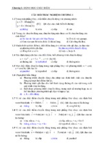
Figure 1.2: Parameter space for the real parts of permittivity and
permeability
According to Picture 1.2 graph, metamaterials can be classified as 4 main types:
-
Negative dielectric materials (Electric materials): ɛ < 0.
Negative permeability materials (Magnetic materials): µ < 0.
Negative refractive index materials (Left – handed materials): n < 0.
Electromagnetic entirely absorbing materials.
3
1.2. Metamaterial perfect absorber (MPA)
1.2.2 Absorption mechanism of metamaterials
MPA structure consist of 3 layers: (i) top layer is a metal circulating structure,
(ii) the center is dielectric structure and (iii) bottom s metal panel.
Recently, there are two main ways popularly used to explain the roles of MPA
structure’s layer.
1.2.2.1. Absorption mechanism based on impedance matching
Electromagnetic waves to the interface surface can be reflected,
transmitted, absorbed, scattered or can be excited by surface plasmonics. The
scientists have demonstrated that for MPA, at the frequency of absorption occurs,
scattering and wave phenomena in surface are negligible [4]. Therefore, we can
calculate the absorptivity as follows:
A=1–R–T
In which: T is the transmission, R is the reflection, A is the Absorption.
In case if the electromagnetic wave is perpendicular to the sample we have
the reflection:
2
z z0
n
R
r
z z0
r n
2
With Z = / is the impedance of MPA and Z0 = 0 / 0 is the impedance
of the air. In case MPA has the third layer is covered by full metallic, T will be
equal to 0, then the absorption is equal to:
2
z z0
n
1 r
A=1–R=1–
z z0
r n
2
So the idea to make an MPA is through the impedance matching of the
material with the air environment to cancel the refraction, while the copper film
at the back layer is thick enough to block all transmission. The cyclic flat
structures by metal in the front and the backside metal plate are separated by the
dielectric, create magnetic resonance. When the electromagnetic wave energy is
dissipated on the metal and the dielectric layer of the material, a small fraction of
the energy is used and maintained to produce magnetic resonance, which is
responsible for the charge. This is the cause of metamaterial perfect absorber.
4
1.2.2.2. Absorption mechanism based on destructive interference
Wave interference theory negates the role of magnetic resonance. In this
case, the two metal layers in the absorbing material act as wave reflecting
surfaces. We will selection the dielectric material with reasonable thickness and
dielectric constant such that the waves are reflected from the metal circular layer
and the overlap of multiple reflections between the two opposite metal layers
leads to destructive reflection completely. In addition, the back metal plate acts
as an electromagnetic interference block that leads to zero transmittance. That is
the cause of the largest absorptivity.
Figure 1.15: Light transmission model to MPA [42].
1.2.3. Some methods of manufacturing transform materials
The first MPA structure proposed by Landy et. al. in 2008. It was a
complicated structure which based on the resonance ring. Therefore, this
structure had a lot of difficulties in fabrication and measurement. Since then, the
process of finding an optimal MPA structure continues to be strong in all
frequencies ranging from GHz, THz to optical frequency [45-50] typically
focusing on a number of structures such as ring structure, dish structure ... by the
geometrical symmetry of them.
Materials absorb at a certain frequency, so they will only be applicable in
limited circumstances. For most applications, the material should be designed
with broad band absorption characteristics, independent from wave polarization.
The independent from wave polarization can be achieved by the symmetry
structures of the top metal elements. To achieve wide band absorption, several
methods have been proposed such as placing more than one resonant structure
on a super unit cell.
Basically, there are two methods for designing transform materials with a
wide frequency range: (i) structures are placed on the same plane as the super
unit cell and (ii) structures are placed on the perpendicular axes to the sample
5
plane. In the case of different sized resonant structures arranged on the same
plane to create the super unit cell, there will be more absorption peak at different
frequencies. When these peaks are close together, a wide absorption band is
obtained. In the case of cells placed on an axis perpendicular to the sample plane,
the sample creates a pyramidal structure, each of which forms a resonance peak.
These resonance peaks are close together, stacked together to form a wide
absorption band [26-27].
1.4. The conclusion of chapter 1
Chapter 1 presents an overview of transform materials: the concept of
transform materials, the classification of transform materials and some
applications of transform materials. In particular, the thesis focuses on how
MPAs operate in different frequency bands with the applications of this material.
In addition, the thesis details the absorption mechanism of the modified material
to explain the structural role of the MPA, as well as the design and fabrication
methods for materials with different frequency bands.
CHAPTER 2: RESEARCH METHODS.
2.1. Approach and method of studying material change
The interactive studies of transform materials with electromagnetic waves
used in the thesis are based on a combination of three methods which are physical
modeling method based on the LC equivalent circuit, the simulation method and
empirical methods.
2.3. Physical modeling method based on the LC equivalent circuit
So far, the interaction of transform materials with electromagnetic waves
has often been explained based on the LC equivalent circuit, proposed by Zhou
et. al. [59]. From this model we can calculate approximately the absorption
frequency, or the frequency at which magnetic resonance phenomena occurs
according to structural parameters.
2.4. The simulation method
The thesis use CST program to study the electromagnetic field interaction
with materials, because CST software that has been featured in prestigious
magazines. Furthermore, the Institute of Materials Science bought this software.
One of the important steps in using the CST software is to set input
parameters, including: materials (available from the bank of available materials
or the inclusion of new materials which are not available in the simulation
6
program), shape, size and structural parameters of the base cell, boundary
conditions, material surroundings. The obtained output parameters include:
complex scattering parameters such as transmission coefficient S21, reflection
coefficient S11, whereby the reflectance R (ω) and the transmittance T (ω) can be
obtained from T(ω) = |S21|2 and R(ω) = |S11|2 and the phases of the electromagnetic
waves passing through the transform material structure allow us to calculate the
absorptivity of material A = 1 - (T + R).
2.5. Experiment methods
Figure 2.13: The process of metamaterial fabrication
The material is selected for operation in the frequency range of 12 - 18 GHz
so the thesis proceeds to make the material by lithography method.
Modeling process: The initial material used for the production of the
sample was a conventional printed circuit board (SME, Korea) consisting of a
FR -4 dielectric (Cu coated both sides).
2.6. Conclusions of Chapter 2
Chapter 2 presents the research methods used in the thesis such as
simulation methods, experimental methods and LC models for studying the
interaction between electromagnetic waves and MM. CST commercial software
based on FIT were used. Theoretical models are calculated based on model of
Zhou's group. Lithography technology is used to fabricate the sample sand a
vector network analyzer is used for the measurements of materials. Chen's
algorithm also is used to calculate other effective parameters of material ( , , n, z
).
7
CHAPTER 3: EFFECTS OF STRUCTURAL PARAMETERS TO THE
WIDTH OF NEGATIVE PERMEABILITY RIGIME OF
METAMATERIALS.
In this thesis, I investigate the expansion of the negative permeability
regime of MMs by CWP structure, which is a traditional and fundamental
structure of MMs with the advantages of simple structure, easy to manufacture
and apply to reality. At first, we increased the width of negative permeability
regime by changing dielectric thickness. Noticeably, we demonstrate the general
function determined magnectic resonance frequency, the expansion of negative
permeability regime based on internal interaction. With the desire to find another
way to expand the regime of negative permeability, we investigate the effects of
symmetry and asymmetry of CWP structure in direction of electric field,
magnetic field and both directions.
3.2 The role of dielectric thickness on the expansion of negative permeability
regime
3.2.1 Theoretical model
Magnetic resonance frequency of CWP structure was calculated by Zhou et al
[59] based on equivalent LC circuit in equation (2.6) (Chapter 2). According to
this equation, magnetic resonance frequency is only depended on the length of
CW and permittivity ɛ of the dielectric spacer. However, some experimental
results shows that the thickness of the dielectric spacer has strongly impact on
magnetic resonance frequency [60, 61, 79]. Therefore, we propose a different
model to calculate inductance Lm and capacitance Cm in LC circuit model by
considering 2 CWs interaction. Then, inductance Lm and capacitance Cm are
defined by:
Lm
0lw
2 w ts
2
td 2ts , Cm
0c1lw
td
(3.1)
Where l is the length, w is the width and ts is the thickness of CW, td is the
thickness of dielectric spacer, c1 is coefficient of 0,2 ≤ 𝑐1 ≤ 0,3.
Magnetic resonance in this case is defined as:
f
c
l 2 c1 (1 2ts / td ) / (1
ts
)
w
(3.2)
Equation (3.2) shows that magnetic resonance frequency is depended not only on
the length of CW and permittivity, but also on the width of CW and the thickness
of dielectric substrate 𝑡 𝑑 . Noticeably, when the thickness of CW ts is much
smaller than the width (ts << w), ts is tiny in comparison to the thickness of
8
dielectric spacer (ts << td), then equation (3.2) revert to (2.6) of Zhou. So,
inductive interaction is not considered in Zhou’s equation.
After that, in order to study the role of the dielectric spacer’s thickness on the
expansion of negative permeability regime. The relative expansion of negative
permeability region is calculated as:
f
1
1
f0
1 F
(3.12)
Where F is structural coefficient [80]:
F
2
0 Nl 2td
Lm
2
td
l w ts
ax a y az
w
td 2ts
2
(3.4)
The results of (3.4) and (3.12) shows that when the thickness of dielectric spacer
increases, the region of negative permeability would be expanded.
3.2.2. Simulated and experimental results
Figure 3.4 shows the simulation and experiment results of transmission of the
structure with different td.
(a)
(b)
Figure 3.4: The simulated (a) and experimental (b) results of transmission
working with td
Table 3.1: Comparison among simulation, experiment and calculation methods
about magnetic resonance frequency working with td
𝑓 𝑚 (GHz)
𝑓 𝑚 (GHz)
𝑓 𝑚 (GHz)
0.4
0.8
Theory
14.02
14.18
Simulation
13.97
14.17
Measure
14.07
14.43
1
14.33
14.27
14.51
𝑡𝑑
(mm)
9
From the Table, we see that the method given is appropriate. In particular,
simulation results and experiments show that the magnetic resonance region is
expanded more effectively when increasing td. For a better observation, Figure
3.5 shows the results of the transmission vs the thickness of the dielectric . The
results show that the width of the transmission is very narrow, the intensity is
weak when the dielectric thickness is small. However, when this thickness
increases to 1 mm, the width of the transmission spectrum is broaden with greater
intensity.
Figure 3.5: Influence of dielectric thickness on transmission spectrum.
Base on Chen's retrieval algorithm [57], Figure 3.6 (a) shows the dependence of
magnetic permeability on the dielectric thickness. The results shows a significant
improvement of the permeability region as the thickness increased. Specifically:
when the dielectric thickness increased from 0.2 to 1.0 mm corresponding to the
osmotic magnitude extending from 3.6% (0.55 GHz at center frequency 13.79
GHz) to 17% (2.42 GHz at center frequency 14.26 GHz). We then calculate the
region width from dielectric thickness to dielectric based on Equation 3.13 of the
theoretical model. The results obtained from the above two methods are
presented in Table 3.2.
Table 3.2: Influence of td on the expansion of negative magnetic region
0.2
0.4
0.6
0.8
∆f/f
Theory
3.7%
6.1%
8.8%
11.8%
∆f/f
Simulation
3.6%
5.7%
8.5%
14.5%
1
15.1%
17.0%
td (mm)
10
The results reconfirm a great agreement between the simulation and
theoretical calculations. Therefore, the thickness of the dielectric layer plays an
important role in widening the working frequency range of our metamaterial.
When the thickness of the dielectric layer increases, the absorption bandwidth
also increases.
3.3. Effect of asymmetry property on negative permeable region
extensibility of CWP structure
3.3.1. Equivalent LC circuit model
Figure 3.7(a) shows asymmetric structure of CWP following the electric
direction through increasing the length of one bar CW and fix the size of
remaining one. Figure 3.7(b) presents circuit model LC which is equivalent to
asymmetric CWP structure. The structure asymmetry leads to changing charge
distribution on two head of a pair CW, creating distinct capacitance values with
a small error C (because of the change of dielectric thickness td which connects
between two opposite charge heads). These capacitance values generate veryclosing magnetic resonances. By this combination, negative permeable region is
expanded.
(a)
(b)
Figure 3.7: (a) CWP structure transform from symmetry to asymmetry (electric
field direction E), (b) equivalent circuit of asymmetric CWP structure.
Following (2.2) and (2.6), we define expression of relative extensibility of
negative permeable region in asymmetric structure in comparison with that of
symmetric structure.
t
f
1 d 1
f
td
(3.13)
Where ∆C/C is capacitance-changing magnitude to initial capacitance value ratio.
11
This ratio is determined based on parameters of asymmetric CWP structure as
follows:
C
C
1
t
1 d
td
1
(3.14)
2
l
t d
1 1 .
td
td
Where:
Figure 3.8 describes the growth of
(3.15)
l
f td
l
,
versus , when l 0 or 0 . It
f
td
td
td
is clear that when l increases, the thickness of dielectric layer connecting two
electrolysis increases, resulting in the increase of relative extensibility of
magnetic resonance region. Particularly, when l 2td , the negative permeable
extensibility can be reached 50%.
1.8
td/td
1.6
f/f
1.4
td/td, f/f
1.2
1.0
0.8
0.6
0.4
0.2
0.0
0.0
0.5
1.0
1.5
2.0
2.5
3.0
l/td
Figure 3.8: The dependence of
l
f td
,
on
.
td
f td
Without loss of generality, we next investigate collapsion of symmetry
property of CWP structure following to magnetic direction of electromagnetic
wave by increasing the width w of one bar and fixing remaining CW bar. Figure
3.9 expresses symmetric CWP structure transformed to asymmetric CWP
structure following w direction (width direction of bar). When increasing the size
of w which is similar to increasing the length l, however, electric field formed
between two bars CW has perpendicular direction with that of projected
electromagnetic waves. Therefore, electric field strengh corresponding to
additional area c1l w is negligible, capacitance formed by structure changes little
from C to C C ' ( C ' : small value). Hence, negative permeable region is
extended but that is negligible.
12
Figure 3.9: CWP structure transformed from symmetry to asymmetry
following magnetic direction
3.3.2. Effect of structural asymmetry under electric direction
In this section, we perform simulation and experiment to CWP asymmetric
material with parameters l = 0 mm, 0.5 mm and 1.0 mm. Network constants of
base cell ax = 3.5 mm, ay = 9mm. Dielectric layer FR-4 is used with dielectric
constant of 4.3 and thickness of td = 0.4 mm. Metal substance in structure is
Cu with conductivity of 5.96.107 Sm-1. The length of bar CW in initial symmetric
structure is l = 5.5 mm, width of w = 1 mm and thickness of ts = 0.036 mm.
Figure 3.10 shows results of spread spectrum based on simulation and experiment
of asymmetric structure CWP with ∆l set at 0, 0.5 and 1.0 mm and ∆l/td set at 0,
1.25, 2.5, respectively.
Figure 3.10: Spread spectrum for simulation and experiment for CWP
structure when breaking structural asymmetry with l = 0, 0.5, 1 mm.
It is clear that the spread spectrum is almost similar for two methods. In
order to observe more clearly about magnetic resonance extensibility, it is better
to simulate with parameter l varying from 0 to 1.2 mm. We can see that (figure
3.11) when l increasing, magnetic resonance region is extended.
In order to re-verify magnetic resonance extensibility by Chen, real part of
permeability magnitude of material is computed based on simulation figure
13
expressed as in figure 3.12. The simulation results shows that, negative
permeability magnitude is extended gradually as ∆l increases. Particularly, the
increasing of ∆l from 0 to 1.25 td corresponds to the negative permeability
magnitude extended from 12.8% (bandwidth of 1.8 GHz at resonant frequency
of 14 GHz) to 23.1% (bandwidth of 3.08 GHz at resonant frequency of 13.38
GHz). At l 2td , the negative permeability value is increased to 24.8%
(bandwidth of 3.31GHz at resonant frequency of 13.376 GHz), at l 2.5td the
negative permeability magnitude is increased to 27.8% (3.7 GHz at central
frequency of 13.3 GHz).
Figure 3.11: Spread spectrum of asymmetric CWP structure when ∆l changes
in range of 0 – 1.2 mm.
Figure 3.12: Permeability magnitude when ∆l is 0, 0.125td, 1.5td, 2td, 2.5td.
In order to explain more clearly about causes of magnetic resonance
extensibility, we perform to simulate distribution of electromagnetic lines
corresponding to following values: ∆l = 0, 1.5td, 2.5td.
14
(a)
(b)
(c)
Figure 3.13: Distribution of electric field at magnetic resonance frequency on
CWP structure with: (a) ∆l = 0, (b) ∆l = 1.5td, (c) ∆l = 2.5td.
It is clear that the distribution of magnetic lines at ∆l = 0, ∆l = 1.5td is almost
similar, this demonstrates that there has been charge transfer to bar head CW 2.
Nevertheless, at ∆l = 2.5td electricity distribution region between bar head CW1 and
extra length of bar CW2 is partially uniform and non-uniform electric field, this
demonstrates that the electrolysis does not transfer completely to head point of
CW2. In other words, the electrolysis only have limited distribution. That is why
negative permeable region initially increases linearly and reaches to saturation
point of about 25 – 28 %.
3.3.3. Effect of structural asymmetry under magnetic direction
Figure 3.15 shows spread spectrum results through simulation and experiment
of asymmetric CWP structure following magnetic direction when ∆w increases.
Figure 3.15: Spread spectrum of asymmetric CWP structure when w rises,
(a) Simulation, (b) Experiment.
From above results, we can see that when the width w of CW2 increases,
magnetic resonance region is extended negligibly. This is explained clearly in
theoretical model in 3.3.1.
By destroying symmetry of structure CWP, it is successful in designing
one structure which negative permeable region is widen. Analytical results have
shown that negative permeable area is extended much more effectively as
15
destroying the structural symmetry under electric direction than magnetic
direction.
3.3.4. The affection of the asymmetrical structure according to two
directions
This thesis continue to study the asymmetrical CWP structure with the
increase of CW2 bar in both length and width. The magnetic resonance region
had been enlarged as expected. However, this structure has a transmittance which
strongly depends on the polar angle that leads to a disadvantages in practical
work. For the desire that find out a structure which can expand the negative
permeability and does not has an impact on the polarization of the
electromagnetic wave, we chose the double rings structure and started to simulate
and experiment the transmission spectrum as well as what we have done with
CWP structure. The result indicates that the asymmetrical double rings structure
also has the same characteristics with the asymmetrical CWP structure.
Although, the transmission spectrum of this structure does not depend on the
polarization of the electromagnetic wave, which is the dominance of the double
rings structure.
3.5. The summary of chapter 3
In summary, chapter 3 has researched the effect of the polarization of
electromagnetic wave on the absorption properties of materials. The results show
that meta-material which has CWP structure strongly depend on the polarization
of electromagnetic wave meanwhile the double ring metamaterial is totally
independent from the polarization.
Besides, the this thesis has worked on the effect of the thickness of the
dielectric layer on the resonance frequency and the width of the negative
permeability frequency region of CWP structure material by using the internal
interaction model (between metal bar in one unit cell). The final result indicates
that the thicker dielectric layer is, the bigger resonance frequency and the width
of negative permeability frequency region are. The result of simulation is
compared to the result of calculation from LC circuit model and verify by
experiments. This is an important result which contribute to research about
absorbing electromagnetic wave metamaterial that has wide active region or
negative refractive index material.
Especially, this thesis has used the theoretical model utilizing LC
equivalent circuit and simulation method. The effect of asymmetry of the unit
cell (CWP and rings structures) on expanding the negative permeability
16
frequency region has researched. The result shows that the asymmetry along the
length of CW bar heavily affects the expending working frequency band from
12.8 to 27.8% when ∆l changes from 0 to 2.5td. Meanwhile, the asymmetry along
the width has a slight effect on the extensibility of working frequency band. The
model has been built conformably for metamaterial not only at GHz frequency
region but also the THz region. The experiment result is quite coincide to the
simulation result and theoretical calculation.
CHAPTER 4: ISOTROPIC METAMATERIAL ELECTROMAGNETIC
WAVE ABSORBER
Structure of perfect absorption material usually concludes the dielectric
layer in the middle, the resonance structure layer in the front face and metal plate
in the back. However, for the common designs, metamaterial can absorb the
electromagnetic wave from only 1 certain direction and cannot absorb from the
opposite direction. In the effort of finding isotropic perfect absorption material,
chapter 4 will propose a symmetric structure based on the transformation of CWP
structure as well as square pair structure, diamond pair structure and ring pair
structure. With this idea, the electromagnetic wave perfect absorber is obtained
by combining the loss of electric resonance and magnetic resonance on the
material.
4.1. Electromagnetic wave isotropic absorption metamaterial
The research of traditional metamaterial absorbers began from CW
structure. But this structure provides the absorbance which depends on the
polarization of electromagnetic wave. With the desire of overcoming that
disadvantage, we turn to research MPA with square structure and rings structure.
Those structures receive electromagnetic wave in only 1 certain direction and
cannot receive it in opposite direction. That leads to a limit in practical
application. In the next part of this thesis, we focus on finding isotropic
metamaterial absorber.
4.2. Isotropic metamaterial electromagnetic wave absorber
To obtain isotropic metamaterial electromagnetic wave absorber, the thesis begin
at CWP structure-metamaterial. This is a traditional structure known as 2 types
of common resonance: magnetic resonance and electric resonance. The
resonance happened at low frequency is magnetic resonance and is electric
resonance at high frequency. The idea here is creating a perfect absorber based
on the combination of the loss at electric and magnetic resonance.
17
4.2.1. Metamaterial absorber based on CWP structure
Figure 4.11: A single unit cell of CWP structure with parameters
Figure 4.12: The simulation results: (a) transmission and (b) absorption
spectra of CWP structure
The unit cell of CWP structure-metamaterial is presented on figure 4.11.
Transmission spectrum and absorption spectrum are presented in figure 4.12. The
results show that there are two absorption peaks at two different frequencies (12.0
and 13.8 GHz). Those two peaks are corresponding with magnetic and electric
resonance frequencies with the absorbance 60% and 40% alternately. This result
suggests us that if shift these two peaks closer to each other, especially
overlapping, we can obtain the perfect metamaterial absorber. However,
controlling the structure parameters is facing with many difficulties because of
their resonance properties [59]. Thus, this thesis focuses on finding material
which has more symmetric structure and easier in controlling the resonances.
4.2.2 Square pair structure metamaterial
Starting from CWP structure metamaterial, by increasing the width (w) as
equal to the length (l), other parameters are maintained, we obtain square pair
structure metamaterial. Figure 4.14 presents absorption spectrum of square
structure material with two absorption peaks at two different frequency (f 1=11.2
GHz and f2=14.7 GHz). The first absorption peak is 52% caused by magnetic
18
- Xem thêm -