SHEETS HAPPEN!
Introduction to the Sheet Set Manager
Whether you design manufactured parts, maps, or buildings, sheets happen! The sheet set
functionality in AutoCAD enables you to efficiently create, manage, and share your entire set of
sheets from one convenient location. At first glance, the powerful functionality offered by the
Sheet Set Manager may seem overwhelming but you don’t have to learn and implement all of the
functionality simultaneously.
Begin taking advantage of sheet set functionality for your current projects with minimal effort by
importing your current drawing layouts into a sheet set. You can easily open drawings from a central
location while you continue to edit them using traditional tools. Create new sheets using traditional
tools and then import those sheets into your current sheet set. Easily plot, publish, archive or create
an electronic transmittal of the entire set of drawings. When you feel comfortable using the most
basic sheet set functionality, you can begin assigning sheet set properties. Using sheet set properties,
you can easily plot to any named page setup, regardless of the page setup that is saved in each of the
drawing layouts. You can also assign your drawing template file to the sheet set making it easy for
you to create new sheets directly from the sheet set manager. Moving on to the most powerful sheet
set functionality, using Fields, enables you to automate the sheet data that is stored in your drawings.
You can create your own fields in the form of custom sheet set properties and then reference those,
and other fields, in your plot stamps, callouts, view labels, and title blocks.
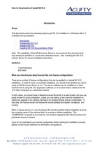
Over the next few months, I will post a series of articles that enable you to progress through these
various levels of implementation from the simplest to the most complex. If you spend only a few
minutes a week, you can create a fully functional sheet set with minimum disruption to your current
workflow. The following diagram provides an overview of the topics I will be covering. If you
haven't seen a demo of sheet sets, you might want to review the Sheet Set videos under the
AutoCAD Awareness post. Those videos were created in AutoCAD 2005 but they apply to
AutoCAD 2006 as well.
Organize sheets
Create new
sheet set
Access sheets
Import existing layouts
Plot using default page setups
Publish to DWF
Assign
sheet set
properties
Create archive/transmittal sets
Using named sheet selections
Plot using any page setup
Create new sheets
Create sheet views
Add view labels
Create
fields
Automate view label data
Automate callout data
Create custom properties
Automate titleblock data
1
SHEETS HAPPEN!
Table of Contents
Introduction to the Sheet Set Manager............................................................................................ 1
Table of Contents............................................................................................................................ 2
Process Overview............................................................................................................................ 3
Implementing Sheet Sets with Minimal Effort ............................................................................... 4
Step 1: Creating a new sheet set ................................................................................................. 4
Step 2: Organizing your sheets ................................................................................................... 6
Step 3: Accessing your sheets..................................................................................................... 7
Step 4: Importing existing layouts ............................................................................................ 10
Step 5: Plotting using default page setups ................................................................................ 11
Step 6: Publishing to DWF ....................................................................................................... 12
Step 7: Creating Archive/Transmittal Sets ............................................................................... 14
Step 8: Using named sheet selections ....................................................................................... 16
Step 9: Assigning sheet set properties ...................................................................................... 17
Step 10: Plotting using any page setup ..................................................................................... 19
Step 11: Creating new sheets .................................................................................................... 24
Step 12: Creating Sheet Views ................................................................................................ 27
Step 13: Adding View Labels ................................................................................................... 29
Implementing Sheet Sets for Maximum Efficiency...................................................................... 31
Step 14: Creating Fields............................................................................................................ 31
Step 15: Automating View Label Data..................................................................................... 33
Step 16: Automating Callout Data............................................................................................ 37
Step 17: Create Custom Properties ........................................................................................... 42
Step 18: Automating Titleblock Data ....................................................................................... 43
Conclusion .................................................................................................................................... 48
2
SHEETS HAPPEN!
Process Overview
I’m often asked about the difference between a “sheet” and a “drawing”. Technically they are the
same thing. The drawing file created by the SSM is just like any drawing you create using
traditional methods. You can draw geometry in model space, create additional layout tabs, etc.
The only technical limitation is that sheets in the SSM sheet list can only point to a layout in a
drawing file. If you want more than one layout in your drawing, you would have to import those
additional layouts into your sheet list. There is no technical reason why you shouldn’t have
multiple layouts in your drawing, however the new sheet set paradigm or “best practice” is to
have one sheet drawing (DWG file) for each sheet in your set. The main benefit for this is to
enable multiple users to work on different sheets at the same time. If you have two sheets that
point to different layouts within the same drawing, the drawing file will be locked as soon as one
person opens one of those sheets… which is how AutoCAD has always worked.
I wanted to provide a quick overview about how sheet sets are intended to work before we move
on to more complex topics.
1. Create your model geometry in its own drawing file (DWG). Continue to create model
geometry in modelspace… Continue to create xrefs, nested xrefs, etc. In that particular
DWG file, focus on nothing but the model… try to forget that the layout tab even exists.
From now on, let the “sheet” deal with the layout.
2. Create a new sheet. As you know by now, creating a new sheet will create a new drawing file
(DWG) with an active layout tab. The sheet name in the sheet list is simply a shortcut to that
layout in the DWG file.
3. Open the sheet, which is really opening the “sheet” drawing file with the layout active.
4. Add resource drawing views to the sheet layout. This is where you create layout viewports
and attach the model drawings as xrefs. Using the sheet set paradigm as it was intended, you
collect design information from other sources (external references attached in model space)
and assemble them into a sheet layout (titleblock, viewports, notes, etc in paper space). The
only objects that should exist in model space are attachments to external files.
5. Add sheet information to the sheet layout. You might add sheet notes or other sheet (paper
space) information that is specific to the sheet. Although you can (technically) draw in model
space, create more layouts, etc. The intention is for this particular DWG file to be a single
sheet with external references to model drawings.
Does it sound like I’m repeating myself? I guess I am.. but I want to be sure you get the point :-).
Aside from separating your Model and Layout into two different drawings, the general concepts
(xrefs, model space, viewports, layouts) should be familiar to you. Although the process I
described isn’t strictly enforced with sheet sets, you should consider how you can transition to
this process so that you can take full advantage of Sheet Set functionality.
3
SHEETS HAPPEN!
Implementing Sheet Sets with Minimal Effort
Even if you only have a few minutes every few days, weeks or months, you can begin taking
advantage of sheet set functionality. This section shows you how!
Step 1: Creating a new sheet set
The first step in implementing sheet set functionality is to create a sheet set. You can create a
sheet set using an example sheet set or by importing existing drawing layouts as sheets. Although
AutoCAD includes several example sheet sets, it is unlikely that they will meet your specific
needs. I suggest that you create your first sheet set by importing drawings from one of your
existing projects. After you configure your first sheet set to meet your needs, you can use it as an
example to create future sheet sets.
In order for you to create a new sheet set based on existing drawings, those drawings must use
layouts. Don’t worry about “messing up” your drawings by creating a sheet set. A sheet set is
simply an XML-based file with a DST extension, which has pointers to your drawing files.
1. Begin the Create Sheet Set wizard.
•
From the File menu, choose New Sheet Set.
•
In the Create Sheet Set wizard, select Existing drawings.
2. Specify the name and location for the sheet set file. The sheet set file is an XML-based
file, with a DST extension. You can think of it as your project file.
•
Enter a name for the sheet set. Typically, this would be the project name.
•
Provide a description for the sheet set. The description is optional.
•
Specify the location to store the sheet set data file. Typically, this would be the main
folder for this particular project.
3. Select the appropriate layouts to import.
•
Choose Browse and navigate to the folder where your project drawings are located.
Typically, this would be the main folder that includes project drawings and/or
drawing subfolders.
•
Expand the folders and drawings so that you can see all the layouts that you want to
include as sheets in the sheet set. If your drawings include multiple layouts, they will
be displayed in the list.
•
Select all of the layouts to be included as sheets in the sheet set. Remember to select
only the drawings/layouts that you want to be represented as sheets. For example, you
wouldn’t select drawings of model geometry that are used as xrefs.
4
SHEETS HAPPEN!
4. Specify the appropriate import options.
•
Choose Import Options.
•
Specify the options that fit your situation. If you want the drawing file name to be
included as part of the sheet name, choose the option to prefix sheet titles with file
name. If you want to create subsets in the sheet set file that match your folders,
choose the option to create subsets based on folder structure. Subsets are like visual
folders that enable you to organize your sheets in the sheet list. If you don’t want to
create a subset of the main folder from which you are importing your drawings, you
can choose Ignore top level folder. Don’t worry too much about these options because
you can always reorganize your sheet set later.
5. Finalize the sheet set.
•
Review the sheet set structure. You can preview your sheet set before completing the
sheet set process. If the sheet set preview is missing sheets or has extra sheets that
should not be included, you can use the back button so select different folders,
drawings, layouts, or import options.
•
Choose Finish. When you are satisfied with the sheet set preview, you can complete
the sheet set creation process.
5
SHEETS HAPPEN!
After exiting the Create Sheet Set wizard, your sheet set data file will automatically open on the
Sheet List tab of the Sheet Set Manager (SSM). The sheet names in the sheet list are like
shortcuts or pointers to the layouts in your DWG files. The drawings have not changed and
AutoCAD didn't create new drawings or folders. All it did was create a sheet set data file with a
list of sheets that link to your existing drawings. Now you can use the SSM to organize and open
your drawing sheets. Right-click on a sheet name and choose Rename and Renumber to enter a
sheet number or change the sheet title. Drag and drop sheets to reorganize them in the sheet list.
And, double-click on the sheet name to open the associated drawing in the drawing editor. Even
if you only use the SSM as a tool for opening your drawings, you will save time and increase
efficiency. You no longer have to navigate through complex folder structures or remember
archaic file names. Just double click on the sheet name!
Are you worried about “messing up” your drawings as you experiment with the sheet set
manager? Read on…
At this point, absolutely nothing in your drawings has changed. However, if the sheet set is open
in the SSM and you open and save the drawings that are being pointed to by the sheet set, a small
piece of data will be saved with the drawings. This data is called a “hint” and it tells the drawing
(DWG) files which sheet set they belong to. Having the hint in a drawing enables AutoCAD to
automatically open the appropriate sheet set even if you open the drawing using traditional
methods. The “hint” is the only change that AutoCAD will make to your original drawing files.
If, for some reason, you want to “undo” the sheet set, you can right-click on the sheet set name
and choose Close Sheet Set and then delete the sheet set data file (DST). If you delete the DST
file without first closing the sheet set, the DST file will be automatically recreated. After you
successfully delete the DST file, you can open and save the associated drawings to remove the
hints.
Step 2: Organizing your sheets
Have you successfully created a sheet set based on the information in the previous Sheets
Happen post? If so, you’re ready to move on to the next step and take advantage of more Sheet
Set functionality. You will use the Sheet Set Manager to organize your sheets.
1. Edit sheet names and numbers.
•
Right-click on a sheet name and choose Rename and Renumber.
•
Enter the appropriate name and number. You can use the Next and Previous buttons
in the dialog box to move up and down the sheet list. In AutoCAD 2006, you have the
option to rename the associated drawing file to match the new sheet title.
6
SHEETS HAPPEN!
2. Remove a sheet from the sheet set.
•
Right-click on a sheet and choose Remove Sheet to remove it form the sheet set.
When you remove a sheet from the sheet set, you are not deleting the drawing from
the folder. You are simply removing the shortcut that points to the drawing.
3. Add subsets.
•
Right-click in the sheet set name or a subset and choose New Subset. You can create
subsets and nested subsets to help organize your sheets on the sheet list.
•
Enter a name for the subset. A subset is like a visual folder in your sheet list. By
default, adding a subset does not create a folder on your hard drive. In AutoCAD
2006, you have the option to create a corresponding folder on the hard drive.
4. Choose OK.
5. Remove subsets.
•
Right-click on a subset and choose Remove Subset. You can only remove subsets that
do not contain sheets.
6. Rearrange sheets and subsets.
•
Drag and drop sheets and subsets to rearrange your sheet list.
As you renumber sheets or drag and drop them to new locations, you will probably notice that
the sheet numbers do not automatically update to reflect their position in the sheet list. If you
want the sheet numbers to correspond to their order in the sheet list, you must manually change
the sheet number as described in the first step. You might wonder what is the purpose for the
sheet number and name. At this point, the sheet name and number are doing nothing more than
enabling you to view and access your drawing sheets by knowing their sheet numbers and/or
names rather than knowing their file names and locations. As we continue to build on sheet set
functionality, the value of the sheet names and numbers will become more obvious.
Step 3: Accessing your sheets
Are you ready for more Sheets Happen? I hope that you are enjoying the ability to easily view
and open the sheets from the Sheet Set Manager (SSM).
The SSM is a great way to organize your sheets and access them from a central location. But
what if you want to include this sheet list as textual information in a drawing? Using the SSM,
7
SHEETS HAPPEN!
you can easily add a sheet list table to one of the sheets in the sheet set. You can even use the
sheet list table to quickly open any of the sheets in the list.
1. Open a sheet in the AutoCAD window..
•
Double-click on the sheet in which you want to add a sheet list table. Typically this
would be a cover sheet or title sheet.
2. Insert a sheet list table.
•
In the SSM, right-click on the sheet set title and choose Insert Sheet List Table.
•
In the Insert Sheet List Table dialog box, select a table style. If you don’t have an
appropriate table style, you can create one. Creating and using table styles is similar
to creating and using text or dimension styles. For example, create a table style called
Sheet List, which uses the appropriate font size, color, etc. Then use that table style
every time you need to create a sheet list. Using table styles will save you time and
ensure consistency from project to project.
•
Specify the Table Data Settings that you want to include in the Sheet List Table. By
default, Sheet Number and Sheet title are included in the list. You can select Add or
Remove to change how many columns are included in the sheet list table and you can
click on the items in the Data Types list to change their content. Use the Move Up
and Move Down buttons to change the order in which the data will be displayed.
•
Choose OK.
•
Place the table on the sheet. The sheet list table is an AutoCAD table object that
contains fields for the sheet set data such as sheet number and sheet name. Since this
is a table object, you can use typical table editing commands to change its
appearance. However, any edits you make will be lost the next time you update the
sheet list. For this reason, you should not make any edits directly to the sheet list
table. If you want to change its appearance, you should edit its table style and/or edit
the sheet list table settings.
8
SHEETS HAPPEN!
3. Edit the Sheet List Table settings. After you insert a sheet list table, you can edit its
settings.
•
Select the sheet list table in the drawing.
•
Right-click and choose Edit Sheet List Table Settings.
•
Change the table style, title, or column settings as necessary. Any changes that you
make using this method will be retained even when you refresh the table data.
4. Change the contents of the sheet list in the SSM
•
Add, remove, rename, or renumber the sheets in the SSM. Notice that the data in the
drawing’s sheet list table, does not change dynamically. You must force the table to
update.
5. Update the sheet list table.
•
Select the sheet list table in the drawing.
•
Right-click and choose Update Sheet List Table. The sheet list table updates to reflect
any changes to the sheet list in the SSM.
6. Access sheets from the sheet list table. You can easily open any of the drawing sheets
from the sheet list table by pressing the CTRL key and picking on the sheet name or
number.
With sheet list tables, you can begin to appreciate how the sheet names, numbers and other data
in the SSM can be used to create meaningful and automated textual data in your drawings.
9
SHEETS HAPPEN!
Step 4: Importing existing layouts
If you’ve been following along with this Sheets Happen series, you created your sheet set using
existing drawings. This method enabled you to quickly create a new sheet set with pointers to the
layouts in those drawings. But what if you have other drawings that you want to include in the
sheet set? For example, maybe a consultant emailed you a new drawing or maybe you forgot to
include a few drawings when you first created the sheet set. You can “import” additional
drawing layouts into your sheet set using the SSM. Actually, I don’t care for the term “import”
because, as you learned in my first Sheets Happen post, the sheets in the SSM sheet list are
nothing more than shortcuts or pointers to layouts in drawings. So, when we say “import” what
we really mean is that you can create a new pointer to an existing drawing.
1. Right-click on the sheet list and choose Import Layout as Sheet. Where you right-click
determines where the new sheet will be added to the sheet list. If you right-click on the
sheet set name, the new sheet will be added to the end of the sheet list. If you right-click
on a subset, the new sheet will be added to the end of the subset. If you right-click on a
sheet, the new sheet will be added below that sheet. Regardless of where you right-click,
you can always drag and drop the new sheet to a proper location.
2. Choose Browse for Drawings and select the drawing that contains the layout you want to
add. After you select a drawing, all of that drawing’s layouts are listed in the Import
Layouts as Sheets dialog box. You can select the layouts that you want to import. You
have the option to prefix the sheet title with the file name.
10
SHEETS HAPPEN!
3. Choose Import Checked. The newly added sheet is just like any other sheet in the sheet
list. You can rename, renumber and reorganize your sheets as necessary.
As you implement sheet set functionality one step at a time, you and other members of the
project team can continue to create new drawings using traditional methods and then import
them into the sheet set using this method.
Step 5: Plotting using default page setups
In the previous Sheets Happen posts, you learned everything you need to know in order to use
the Sheet Set Manager (SSM) as your primary tool for accessing drawings. You created a new
sheet set using existing drawing layouts and you learned how to import additional sheets into that
sheet set. Combine that with the ability to plot your sheets using their default page setups and
you can save a huge amount of time over the life of your project. Even if only take advantage of
sheet set functionality for these few tasks, it will have been worth your effort.
Think about how you plot your sheets without using the SSM. Imagine that you’re working on
Project B when someone sends you an urgent request asking you to plot all of the sheets for
Project A. You stop what you are doing and begin opening the drawings for Project A, one at a
time. Of course, that is after you navigate to the Project A folder and locate the correct
subfolders and drawing files. Project A includes several versions of subfolders and drawing files
and you have to be careful to find the correct ones. Each time you find an appropriate drawing;
you open it, select the appropriate layout, and plot. While you are busy opening and plotting
drawings, your coworkers are frustrated. They are trying to edit these Project A drawings but
they can’t because you have the drawings locked.
Using the SSM for plotting can significantly reduce the amount of time you spend plotting your
drawings. Even if you are unfamiliar with a project, you can quickly plot the entire sheet set
without having to open and view each drawing file. Your coworkers can continue editing the
drawings while you use the SSM to send the entire set of sheets to their default plot device. Keep
in mind, however, that this method assumes each sheet has been saved with the proper plot
11
SHEETS HAPPEN!
information. Using this method is the same as opening the drawing, selecting the layout and
choosing Plot, without making any changes to the page setup. In a later post, I’ll describe how
you can override the default page setups on the fly!
1. Select sheets to plot. In the SSM, select the sheets you want to plot. You can use the Shift
and CTRL keys to specify a range or specific sheets. You can also select subsets or the
entire sheet set.
2. Right-click and choose Publish>Publish to Plotter.
Step 6: Publishing to DWF
So… how are your sheet sets coming along? I hope you have been enjoying the easy access and
quick plotting capabilities of the Sheet Set Manager. One of the attendees in my SSM class at
AU told me that his department has only implemented enough sheet set functionality to plot from
the SSM but that capability alone makes the SSM worth while! I’m happy to hear that but don’t
stop now! There is so much more!
You can continue to take advantage of sheet set functionality by publishing your sheets to a
DWF file. If you are not familiar with DWF, just try it and see what happens! DWF (Design
Web Format) enables you to share your design data with other people in a secure and lightweight
format. It is like plotting to PDF but better. Unlike PDF, DWF files are vector based so you get
better quality with smaller file sizes. You can post the DWF to a project site or send it via email.
The recipient can then view and plot it to scale using the free DWF viewer.
Prior to publishing your sheets to a DWF file, you can set various options.
1. Set DWF publishing options.
•
Right-click in the sheet list and choose Publish>Sheet Set Publish Options.
•
Set various options. You can specify the location where the DWF file will be created
and you can specify either a single-sheet or multi-sheet DWF. If you select singlesheet DWF, a separate DWF file will be created for each of the sheets that you select
from the sheet set and the DWF file names will correspond to the sheet names. If you
select multi-sheet DWF, all of the sheets that you select will be sent to a single DWF
file. By default, the DWF file name corresponds to the sheet set name. You can enter
an alternate name in the sheet set publish options or you can ask AutoCAD to prompt
you for a name during the publish operation. Regardless of whether you publish to a
single- or multi-sheet DWF, you have the option of including a password with the
DWF file. If you include a password, the recipient of the DWF file will be prompted
to enter the password before viewing the DWF in the viewer.
One of the many advantages of using DWF over PDF is that you can include
intelligent data with you files including layers, sheet and sheet set information, and
block information. You can even specify a block template file that defines which
properties and attributes to publish from selected blocks. The block template is
similar to using a data extraction template to create a table with block data. The more
information you include with your DWF file, the more flexibility the recipient will
have when viewing it.
12
SHEETS HAPPEN!
2. Choose OK.
3. Select sheets to publish. In the SSM, select the sheets you want to publish. You can use
the Shift and CTRL keys to specify a range or specific sheets. You can also select subsets
or the entire sheet set.
4. Publish selected sheets.
•
Right-click and choose Publish>Publish to DWF. You can also select the Publish to
DWF button in the upper right corner of the SSM. The DWF file(s) will be created
using the current sheet set publish options. By default, the DWF file is published in
the background, similar to plotting. You will be notified when the publish operation is
complete.
•
Close the Plot and Publish balloon notification.
5. View the DWF file. The DWF viewer is automatically installed with AutoCAD enabling
you to view the DWF file before posting or emailing it.
•
Right-click on the Plot/Publish icon and select View DWF File.
•
In the DWF viewer, select different sheets to view and try viewing some of the data
such as layers, blocks, etc.
13
SHEETS HAPPEN!
Publishing to DWF is just that easy! The recipients of your DWF file can view and plot the
sheets while you rest assured that the design data remains unchanged. If the recipients of your
DWF files are using DWF Composer, a more advanced DWF viewing tool, they can measure
and markup the DWF file and then return it to you. For more information about working with
DWF files visit www.autodesk.com/viewers. You can also check out the Viewer and Markup
videos in my October “AutoCAD Awareness” post.
Step 7: Creating Archive/Transmittal Sets
Did you ever send someone a drawing file only to have them respond with an urgent request to
“SEND THE XREFS!” You can avoid those urgent requests with eTransmit because it
automatically packages the drawing and its associated files, such as xrefs, images, and fonts, into
a single folder, zip or self-extracting executable. When you send the transmittal set rather than
just the drawing, you help ensure that the recipient has all of the necessary files. You can use
eTransmit without using sheet sets. However, when you use eTransmit in the current drawing, it
only packages the files associated with that particular drawing. You can manually add other
drawings to the transmittal set, but that process can be time-consuming for many drawings.
Using eTransmit with a sheet set enables you to package multiple drawings and all of their
associated files with minimal effort.
1. Close or save drawings. You must close or save any open sheet set drawings that have
been edited. However, if you close all of the drawings, AutoCAD will be in a zerodocument state and most of the right-click options will be grayed out. If that happens, just
use File>New to create a new blank drawing.
2. Select sheets to include in the transmittal set. In the SSM, you can use the Shift and Ctrl
keys to select a range or specific sheets. You can also select subsets or the entire sheet
set.
3. Create a transmittal set.
•
Right-click and choose eTransmit.
14
SHEETS HAPPEN!
•
In the Create Transmittal dialog box, select Transmittal Setups.
•
In the Transmittal Setups dialog box, create or modify a transmittal setup. By default,
AutoCAD includes a Standard transmittal setup. You can modify the Standard
transmittal setup or create any number of new ones. For example, you might create a
transmittal setup to save all the drawings to a zip file in AutoCAD 2000 file format
while another one saves all the drawings to a self-extracting executable with all of the
reference paths removed. The transmittal setups you create for a sheet set are saved in
the sheet set data file. However, you can import transmittal setups from another sheet
set using the Import option in the Transmittal Setups dialog box. When you create
transmittal setups in a drawing without using sheet set functionality, they are saved in
the registry under the current user.
•
In the Create Transmittal dialog box, you can use the Sheets, Files Tree, or Files
Table tabs to add and remove files from the transmittal set. When you use eTransmit
in a drawing without a sheet set, the Sheets tab is not displayed.
•
Choose View Report if you want to see a comprehensive list of all the files and sheet
set information included with the transmittal set.
•
Choose OK to close the Create Transmittal dialog box and create the transmittal set.
4. Create an Archive set. Creating an archive set is very similar to creating a transmittal set.
They use the same underlying technology but Archive has been simplified for the single
purpose of archiving the sheet set. You might create an archive set only one time, at the
end of a project. Or you might create them at key milestones throughout the project.
•
On the Sheet List tab of the SSM, right-click on the sheet set name and choose
Archive. Unlike eTransmit, Archive is only available for a sheet set. Similar to
eTransmit, you must close or save any open drawings that have been edited. But
remember, you can’t be in zero-doc state.
•
In the Archive a Sheet Set dialog box, you can modify Archive Setup options similar
to eTransmit. Like eTransmit, the Archive setup is saved with the sheet set data file.
15
SHEETS HAPPEN!
However, unlike eTransmit, you can only have one Archive Setup and you cannot
import it from another sheet set.
•
You can use the Sheets, Files Tree, or Files Table tabs to add and remove files from
the archive set.
Whether you create a transmittal set or an archive set, the original files are not modified.
AutoCAD makes a copy of the files using the criteria you specified in the transmittal or archive
setup.
Step 8: Using named sheet selections
As you continue to use more sheet set functionality, you might want to have different sheet
selections. For example, you might want to plot the entire sheet set for a design review and
create a transmittal set of just the floor plan and lighting drawings for the lighting vendor. You
may find yourself wanting to access these various selections of sheets many times throughout the
project. Rather than having to scroll through and select the appropriate sheets each time, you can
create named sheet selections.
1. Create Named sheet selections. You will repeat this process for each named sheet selection
you want to create.
•
Select several sheets and/or subsets using the Shift or Ctrl keys. These are the sheets that
you want to include in the named sheet selection.
•
From the Sheet Selections drop-down list, choose Create. If you have multiple sheets
selected, you can also right-click and choose Save Sheet Selection.
16
SHEETS HAPPEN!
•
Enter a name for the sheet selection. You might create named sheet selections such as
Client set, Design review, Architectural sheets, and Landscape sheets.
•
Choose OK.
2. Restore different named sheet selections.
•
From the Sheet Selections drop-down list, choose one of your named sheet selections.
The sheets that you had selected when you created the named sheet selection are
highlighted and ready for you to plot, publish to DWF, or etransmit.
3. Manage named sheet selections.
•
From the Sheet Selections drop-down list, select Manage.
•
Choose Rename or Delete.
Step 9: Assigning sheet set properties
If you have been following along with the Sheets Happen series, you’ve been able to take
advantage of sheet set functionality with minimal effort. However, if you want to fully
implement sheet sets for maximum productivity, you will need to assign various sheet set
properties.
You will find the sheet set properties by right-clicking on the sheet set title in the Sheet List tab
of the Sheet Set Manager and selecting Properties.
Note that you will also find a Properties option in the right-click menu for subsets and sheets.
Depending on which item you right-click, selecting Properties will display different dialog boxes
(Sheet Set Properties, Subset Properties, Sheet Properties) enabling you to view and change the
relevant properties for that particular item. I'm going to focus on the Sheet Set Properties.
17
SHEETS HAPPEN!
By default (in AutoCAD 2006), the Sheet Set Properties dialog includes three sections: Sheet
Set, Project Control, and Creation. The Sheet Set section includes properties for the Name, Sheet
set data file, Description, Resource drawing locations, Label block for views, Callout blocks, and
Page setup overrides files. The Name property is for the name of the sheet set. It uses the name
you provided when you created the sheet set with the Create Sheet Set Wizard (see Sheets
Happen! Step 1: Creating a new sheet set). That name was also used for the name of the sheet set
data file (DST) as you can see by viewing the Sheet set data file property. You can change the
name of the sheet set using the Sheet Set Properties dialog box. However, the name of the sheet
set data file will not change. If you want to change the name of the sheet set data file, you must
close the sheet set in the Sheet Set Manager and then use Windows Explorer to rename the DST
file. The Description property may be blank depending if you entered a description when you
first created the sheet set. You can create or edit the description in the Sheet Set Properties if you
wish. The Project Control section is not available in AutoCAD 2005. However you can create
custom sheet set properties to accomplish the same thing. I’ll discuss custom sheet set properties
and all of the remaining sheet set properties in future posts as they become relevant.
18
SHEETS HAPPEN!
Step 10: Plotting using any page setup
Note: I added the December 30, 2005 posting, “Resolve to save your page setups”, to this
section.
Named page setups were introduced in AutoCAD 2000 but they were somewhat hidden and
relatively unused. In AutoCAD 2005, with the introduction of sheet sets, named page setups
were slightly redesigned and made more visible. However, I’m still surprised at how many
people don’t use (or even know about) named page setups. Regardless of your version of
AutoCAD (2000 – 2006), if you plot (and who doesn’t?!?), you will find value in named page
setups!
You can create any number of named page setups and easily restore them for any layout. For
example, you might create one named page setup called Final Plot that plots the layout to your
HP DesignJet on an E-size sheet at a scale of 1:1, and a second one called Test Plot that plots the
extents to your LaserJet on a letter-size sheet, scaled to fit.
If you have AutoCAD 2005 or 2006, you are probably familiar with the Page Setup Manager but
you may not have used it to save a named page setup. The Page Setup Manager automatically
displays when you try to access the page setup for a model or layout tab. By default, AutoCAD
creates an unnamed page setup for the current tab. If you select the Modify button, you can
change the page setup options for that particular layout (or model). However, without using
named page setups, you have to repeat the process for every layout. Using named page setups,
you can set the options one time and then easily apply them to any layout. The process for
creating named page setups is simple. Once they are created, named page setups will save you
clicks and time!
1. From the File menu, choose Page Setup Manager. You can also right-click on the model or
layout tab to find the Page Setup Manager.
2. Choose New.
3. In the New Page Setup dialog box, enter the name of the page setup. Possible names might
include: Test Plot, Final Plot, LaserJet Letter-size, DesignJet E-size, E-size Monochrome,
etc.
4. In the Page Setup dialog box, specify the device and other page setup options and then
choose OK.
19
SHEETS HAPPEN!
5. Continue to create new page setups for the various page setup configurations you might need.
6. In the Page Setup Manager, select the named page setup you want to use for the current
layout (or model) and choose Set Current.
All of the named page setups are saved in the current drawing but you can use the Import option
to access named page setups from other drawings. Ideally, you would create all your named page
setups in a template file so that they are automatically included in new drawings and easily
accessible from a central location to import into existing drawings.
20
- Xem thêm -