6
Planning and
CHAPTER
Designing
Wireless Data
and Satellite
Applications
Copyright 2003 by The McGraw-Hill Companies, Inc. Click Here for Terms of Use.
156
Part 2:
Planning and Designing Data Applications
As you know, wireless data networks are composed of two components—
access points and client devices. The components communicate with
each other via radio-frequency transmissions, eliminating the need for
cabling.
So, what do you need to plan, design, and build a wireless data network? Let’s take a look.
Access Points
A wireless data network is planned, designed, and built around one or
more access points that act like hubs, which send and receive radio signals to and from PCs equipped with wireless data client devices. The
access point can be a stand-alone device, forming the core of the network,
or it can connect via cabling to a conventional local-area network (LAN).
You can link multiple access points to a LAN, creating wireless data segments throughout your facility. (The Glossary defines many technical
terms, abbreviations, and acronyms used in the book.)
Client Devices
To communicate with the access point, each notebook or desktop PC
needs a special wireless data networking card. Like the network interface cards (NICs) of cabled networks,3 these cards enable the devices
to communicate with the access point. They install easily in the PC
slots of laptop computers or the PCI slots of desktop devices, or link to
USB ports. A unique feature found on the wireless data PC card of a
leading vendor features a small antenna that retracts when not in use.
This is extremely beneficial, given the mobility of laptop computers.
You can also connect any device that doesn’t have a PC or PCI card
slot to your wireless data network by using an Ethernet client bridge
that works with any device that has an Ethernet or serial port (printers, scanners etc.).
Once the access point is plugged into a power outlet and the networked devices are properly equipped with wireless data cards, network
connections are made automatically when the devices are in range of the
hub. The range of a wireless data network in standard office environments can be several hundred feet.
Wireless data networks operate like wired networks and deliver the
same productivity benefits and efficiencies. Users will be able to share
files, applications, peripherals, and Internet access.
Chapter 6: Planning, Designing Data, Satellite Applications
157
Planning and Designing a Wireless
Data Network
Now, what type of features should you plan and design into a wireless
data network? In other words, you need to plan, design, and build the
following features and solutions:
Standards-based and WiFi certified
Simple to install
Robust and reliable
Scability
Ease of use
Web server for easy administration
Security
A site survey application
Installation
Standards-Based and WiFi Certified
As previously explained, WiFi is a robust and proved industry-wide network standard that ensures your wireless data products will interoperate with WiFi-certified products from major networking vendors. With a
WiFi-based system, you will have compatibility with the greatest number of wireless data products and will avoid the high costs and limited
selection of proprietary, single-vendor solutions. Additionally, select a
wireless solution that is standards based and fully interoperable with
Ethernet and Fast Ethernet networks. This will enable your wireless
data network to work seamlessly with either your existing cabled LAN
or one that you deploy in the future.
Simple to Install
Your wireless data solution should be plug and play, requiring only minutes to install. Plug it in and start networking. For even greater ease of
deployment, your solution should support the Dynamic Host Configuration Protocol (DHCP), which will automatically assign IP addresses to
wireless data clients. Rather than install a DHCP server in a standalone device to provide this timesaving capability, select wireless data
hubs that feature DHCP servers built into them.
158
Part 2:
Planning and Designing Data Applications
If you are adding a wireless data system onto your existing Ethernet network, an access point that can be powered over standard Ethernet cabling
makes a great choice. This enables you to run the access point using lowvoltage dc power over the same cabling you use for your data—eliminating
the need for a local power outlet and power cable for each access point
device.
Robust and Reliable
Consider robust wireless data solutions that have ranges of at least 300 ft.
These systems will provide your employees with considerable mobility
around your facility. You may choose a superior system that can automatically scan the environment to select the best radio-frequency (RF) signal
available for maximum communications between the access point and
client devices. To guarantee connectivity at the fastest possible rate, even
at long range or over noisy environments, make sure your system will
dynamically shift rates according to changing signal strengths and distance from the access point. Additionally, select wireless data PC cards for
your laptop computers that offer retractable antennas to prevent breakage when the devices are moved about.
Scalability
A good wireless data hub should support approximately 60 simultaneous
users. This should enable you to expand your network cost-effectively
simply by installing wireless data cards in additional computers and
network-ready printers. For printers or other peripherals that do not
support networking, you should connect them to your wireless data network with a wireless USB adapter or an Ethernet client bridge.
Ease of Use
A wireless data network should be as effortless for users to operate as a
cabled network. To ensure maximum performance and reliability at all
times, chose a system that can automatically scan the local environment to
select the strongest available radio-frequency channel for communications.
If you plan to connect multiple wireless data hubs to an existing
cabled network, consider a solution that features automatic network
connections. When a user roams beyond the boundaries of one wireless
data hub into the range of another, an automatic network connection
capability will seamlessly transfer the user’s communications to the lat-
Chapter 6: Planning, Designing Data, Satellite Applications
159
ter device, even across router boundaries, without ever reconfiguring the
IP address manually. This is particularly useful for businesses with multiple facilities that are connected via the wide-area network (WAN). As a
result, users will be able to move about your facility and beyond freely
and remain connected to the network.
Web Server for Easy Administration
You will simplify administration of your wireless data network if you
select an access point with a built-in Web server. This allows you to
access and set configuration parameters, monitor performance, and run
diagnostics from a Web browser.
Security
Choose a wireless data solution that offers multiple security layers,
including encryption and user authentication. A secure solution will offer
at least 40-bit encryption, and advanced systems can provide 128-bit
encryption. For both ease of use and the strongest protection, select a
superior solution that automatically generates a new 128-bit key for every
wireless data networking session without users entering a key manually.
Also, consider a system that features user authentication, requiring workers to enter a password before accessing the network.
A Site Survey Application
Your wireless data networking solution should include a site survey utility.
The utility can help you determine the optimal location of wireless data
hubs and the number of hubs you need to support your users. It will help
you to deploy a wireless data solution effectively and efficiently.
Installation
Do you need a technician to install your wireless data network? Generally,
you can install a wireless data network yourself. A wireless data solution
is an effective strategy if your organization lacks networking experience.
Some advanced systems can be set up in a minute or so. Installation and
deployment procedures are discussed in specific detail in Part 3,
“Installing and Deploying Wireless High-Speed Data Networks” (Chaps.
13 to 17).
160
Part 2:
Planning and Designing Data Applications
Now, let’s look at why the planning and design of a large-scale wireless data LAN poses a number of interesting questions. This part of the
chapter describes the approaches developed and taken in the planning
and design of wireless data networks.
A large-scale wireless data LAN must be planned and designed so
that all of the target space has radio coverage (there are no coverage
gaps). It must also be designed so that its capacity is adequate to carry
the expected load. These requirements generally can be met by using
the proper combination of access point locations, frequency assignments,
and receiver threshold settings.
Large-Scale Wireless Data LAN
Planning and Design
Wireless data LANs (WDLANs) were originally intended to allow localarea network (LAN) connections where premises wiring systems were
inadequate to support conventional wired LANs. During the 1990s,
because the equipment became available in the PCMCIA form factor,
WDLANs came to be identified with mobility. They can provide service
to mobile computers throughout a building or throughout a campus.
Generally, wireless data LANs operate in the unlicensed industrial,
scientific, and medical (ISM) bands at 915 MHz, 2.4 GHz, and 5 GHz.
The original WDLAN standard IEEE 802.11 (with speeds up to 2 Mbps)
allows either direct-sequence or frequency-hopping spread spectrum to
be used in the 2.4-GHz band. It also allows operation at infrared frequencies. The high-rate WDLAN standard IEEE 802.11b provides operation at speeds up to 11 Mbps in the 2.4-GHz band and uses a modified
version of the IEEE 802.11 direct-sequence spread-spectrum technique.
A newer high-rate standard, IEEE 802.11a, uses orthogonal frequencydivision multiplexing (OFDM) to provide for operation in the 5-GHz
UNII band at speeds up to 54 Mbps. IEEE 802.11b equipment is readily
available in the market, and IEEE 802.11a equipment is expected to
become available by early 2003.
WDLANs typically include both network adapters (NAs) and access
points (APs). The NA is available as a PC card that is installed in a
mobile computer and gives it access to the AP. The NA includes a transmitter, receiver, antenna, and hardware that provides a data interface to
the mobile computer. The AP is a data bridge/radio base station that is
mounted in a fixed position and connected to a wired LAN. The AP, which
includes transmitter, receiver, antenna, and bridge, allows NA-equipped
mobile computers to communicate with the wired LAN. The bridge, which
Chapter 6: Planning, Designing Data, Satellite Applications
161
is part of the AP, routes packets to and from the wired network as appropriate.
Each AP has a radio range, for communication with NAs, from approximately 20 to more than 300 m, depending on the specific product, antennas, and operating environment. The APs can be interfaced to IEEE
802.3 (Ethernet) wired LANs.
Most wireless data LANs allow “roaming”; that is, mobile computers
can accept a handoff as they move from the coverage area of one AP to the
coverage area of another, so service is continuous. In order for this handoff
to be successful, it is necessary that the tables of the bridges contained in
each AP be updated as mobiles move from one AP coverage area to another.
In wireless data LANs, direct peer-to-peer (mobile-to-mobile) communication can be provided in one of two ways. In some wireless data LANs, it is
possible for a mobile to communicate directly with another mobile. In others, two mobiles, even though they are both within range of each other, can
communicate only by having their transmissions relayed by an AP.
The use of direct-sequence spread spectrum (DSSS) in IEEE 802.11
and 802.11b spreads the signal over a wide bandwidth, allowing transmissions to be robust against various kinds of interference and multipath effects. IEEE 802.11b WDLANs operate at raw data rates of up to
11 Mbps and occupy a transmission bandwidth of approximately 26
MHz. Exact spectrum allocations for 2.4-GHz ISM differ from one country to another. In North America the band is 2.400 to 2.4835 GHz.
IEEE 802.11 and 802.11b use the carrier sense multiple access
(CSMA) with collision avoidance (CA) medium access scheme, which is
similar to the CSMA/CD scheme used in IEEE 802.3 (Ethernet) LANs.
With wireless data transmissions, the collision detect (CD) technique
used in wired LANs cannot be done effectively, since the transmitter signal strength at its own antenna will be so much stronger than the signal
received from any other transmitter. Instead, CSMA/CA adds a number
of features to the basic CSMA scheme to greatly reduce the number of
collisions that might occur if only CSMA (without CD) were used.
Planning and Design Challenges
The challenges in building such a large wireless data network are significant. They include planning and designing the network so that coverage blankets, for example, a campus, and adequate capacity is provided
to handle the traffic load generated by the campus community. The
WDLAN plan and design is defined as including two components: selection of AP location and assignment of radio frequencies to APs.
In laying out a multiple-AP wireless data LAN installation, one must
take care to ensure that adequate radio coverage will be provided
162
Part 2:
Planning and Designing Data Applications
throughout the service area by carefully locating the APs. Experience
shows that the layout must be based on measurements, not just on ruleof-thumb calculations. These measurements involve extensive testing
and careful consideration of radio propagation issues when the service
area is large, such as an entire campus.
The layout and construction of buildings determine the coverage area
of each AP. Typical transmission ranges go up to 300 m in an open environment, but this range may be reduced to 20 to 60 m through walls and
other partitions in some office environments. Wood, plaster, and glass are
not serious barriers to wireless data LAN radio transmissions, but brick
and concrete walls can be significant ones; the greatest obstacle to radio
transmissions commonly found in office environments is metal, such as in
desks, filing cabinets, reinforced concrete, and elevator shafts.
Network performance is also an issue. An AP and the mobile computers within its coverage area operate something like the computers on an
Ethernet segment. That is, there is only a finite amount of bandwidth
available, and it must be shared by the APs and mobile computers. The
IEEE 802.11b protocol, using CSMA/CA, provides a mechanism that
allows all units to share the same bandwidth resource.
The Carrier Sense Multiple-Access/Collision Avoidance (CSMA/CA)
protocol makes radio interference between APs and NAs operating on the
same radio channel a particular challenge. If one AP can hear another AP
or a distant NA, it will defer, just as it would defer to a mobile unit transmitting within its primary coverage area. Thus, interference between
adjacent APs degrades performance. Similarly, if a mobile unit can be
heard by more than one AP, all of these APs will defer, thus degrading
performance.
Design Approach
In selecting AP locations, one must avoid coverage gaps, areas where no
service will be available to users. On the other hand, one would like to
space the APs as far apart as possible to minimize the cost of equipment
and installation. Another reason to space the APs far apart is that coverage overlap between APs operating on the same radio channel (cochannel overlap) degrades performance. Minimizing overlap between APs’
coverage areas when one is selecting AP locations helps to minimize
cochannel overlap.
NOTE One should not overprovision a wireless LAN by using more APs
than necessary.
The rules of thumb are inadequate in doing this type of planning and
design. Rather, each building plan and design must be based on careful
Chapter 6: Planning, Designing Data, Satellite Applications
163
signal strength measurements. This is particularly challenging because
the building is a three-dimensional space, and an AP located on one floor
of the building provides signal coverage to adjacent floors of the same
building and perhaps to other buildings as well.
After the APs have been located and their coverage areas measured,
radio channels are assigned to the APs. Eleven DSSS radio channels are
available in the 2.400- to 2.4835-GHz band used in North America; of
these, there are three that have minimal spectral overlap. These are
channels 1, 6, and 11. Thus, in North America, APs can operate on three
separate noninterfering channels. Furthermore, some NAs can switch
between channels in order to talk with the AP providing the best signal
strength or the one with the lightest traffic load. Use of multiple channels can be very helpful in minimizing cochannel overlap, which would
otherwise degrade performance.
One approach is to assign one of these three channels to each of the
APs and to do so in a way that provides the smallest possible cochannel
coverage overlap. Making these frequency assignments is essentially a
map coloring problem, and there are various algorithms that give optimal or near-optimal assignment of the three radio channels, given a particular set of AP placements and coverage areas.
The design must also consider service to areas with high and low densities of users. If many users of mobile computers are located in a small
area (a high-density area), it may be necessary to use special design
techniques in these areas. Most parts of a campus will be low-density
areas. However, there will be some areas, particularly classrooms and
lecture halls, that will be high-density areas, with high concentrations
of users, mostly students.
Two design layout techniques that are useful in high-density situations are increasing receiver threshold settings and using multiple radio
channels. Some wireless data LAN products allow one to set receiver
threshold, thus controlling the size of the coverage area of the AP. A coverage-oriented design should use the minimum receiver threshold setting, maximizing the size of the coverage area of each AP. When capacity
issues are considered, however, one may wish to use higher AP receiver
threshold settings in high-density areas, reducing the coverage area of
each AP.
The use of multiple radio channels can allow the use of multiple APs
to provide coverage in the same physical space. For example, one might
use three APs operating on three different channels to cover a large lecture hall with a high density of users. The exact capacity improvement
is dependent on the algorithm used by the mobile unit to select an AP. A
load-balancing algorithm will provide the greatest capacity increase. An
algorithm that selects the strongest AP signal will not provide as great
an increase.
164
Part 2:
Planning and Designing Data Applications
Thus, one would like to carry out a plan and design that is coverageoriented in most (low-density) areas, minimizing the number of APs, but
capacity-oriented in some (high-density) areas, assuring adequate
capacity to serve all users in these areas. The coverage-oriented design
in the low-density areas minimizes the cost of APs, but the use of extra
APs with higher receiver thresholds in high-density areas can be used to
provide extra capacity.
Planning and Design Procedure
Because radio propagation inside a building is frequently anomalous
and seldom completely predictable, the planning and design of an indoor
wireless data installation must be iterative. The planning and design procedure includes five steps:
Initial selection of AP locations
Test and redesign, which is adjusting the access point locations based
on signal strength measurements
Creation of a coverage map
Assignment of frequencies to APs
Audit, which is documenting the AP locations and a final set of signal
strength measurements at the frequencies selected1
In the next part of the chapter, a technique for carrying out the first
step is described, along with the initial selection of access point locations.
This initial plan and design is tentative and is intended to be modified in
the second step of the planning and design process.
After the initial selection of AP locations is complete, APs are temporarily installed at the locations selected. The coverage areas of these
APs and the overlaps between coverage areas are measured. Typically,
coverage gaps and/or excessive overlaps are found. On the basis of the
measurement results, the AP locations are adjusted as needed, more
measurements are done, more adjustments are made, and so on, until
an acceptable plan and design is found. The process is an iterative one.
It may be necessary to repeat this planning and design-test-redesign
cycle several times to find an acceptable solution.
After the final AP locations have been selected, a coverage map of the
planning and design area is created. This coverage map may be created
by using AutoCAD or other computer-based techniques.
After AP locations have been finalized, frequencies are assigned to
the APs in a way that minimizes cochannel coverage overlap. Then, a
complete set of coverage measurements (audit) is made for the entire
Chapter 6: Planning, Designing Data, Satellite Applications
165
building with the APs operating at the selected frequencies, and the
results of these measurements are documented. At this point, the design
is considered complete. The coverage map is updated to reflect final AP
locations, coverage measurements, and frequency assignments.
Determining the Access Points’ Initial
Locations
Now let’s look at a procedure for the initial selection of AP locations in a
low-density area. In selecting locations for the APs, one should place
them so that there are no coverage gaps in the target space, and the coverage overlaps between and among APs are minimized. While the first
point is obvious, the second is more important than is immediately
apparent. If too many APs are used, the cost of equipment and installation will be higher than necessary, and the performance of the network
may also be degraded if the final design involves a great deal of cochannel coverage overlap. The amount of cochannel coverage overlap is
determined by both AP placement and AP frequency assignment.
The coverage area is defined in terms of a specified received signal
strength. This threshold level is selected in order to provide an adequate
signal-to-noise ratio (S/N) and some additional margin. If, for example, in
designing an IEEE 802.11b WDLAN, one measures an ambient noise
level of ⫺95 dBm and a 10-dB S/N is needed to ensure excellent performance, one might decide to allow an extra 5 dB of margin to allow for
noise levels higher than ⫺95 dBm. In this case, one would select a threshold of ⫺80 dBm.
When high-density spaces exist, it is suggested that the AP placement
first be done for these spaces and that the remaining low-density spaces
then be designed, filling in the gaps between high-density spaces.
AP Placement In this part of the chapter, an idealized notion of AP
coverage is introduced. This description is offered only to provide some
insight into the layout approaches that can be used in different types of
buildings.
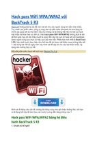
The coverage volume of the AP is idealized as three coaxial cylinders,
as shown in Fig. 6-1.1 The middle cylinder, representing coverage on the
floor on which the axis point is located, has radius R. The AP is located on
the axis of this cylinder. The upper and lower cylinders, representing coverage on the floors above and below the one on which the AP is located,
have radius R⬘, which is less than R. The height of each of the three cylinders is the height of a floor in the building. These three cylinders can be
thought of as a single object, which moves about as the location of the AP
moves.
166
Part 2:
Planning and Designing Data Applications
R'
Figure 6-1
Idealized access point
coverage.
R
R'
The problem of locating APs within a building can be viewed as a
problem of locating these shapes within the building in such a way that
all spaces are filled with as little overlap as possible. While coverage volumes are not actually perfect cylinders, one can find the average coverage radius inside a building and use this as the radius of an idealized
cylindrical coverage volume. This can be achieved by defining an acceptable signal strength threshold (⫺80 dBm) and determining the average
distance from the AP at which signals fall below the threshold.
Procedure The initial selection of AP locations begins with a complete
set of signal strength measurements within the building. Signal
strength measurements should be made in all areas of the building,
with particular attention to the building’s construction so that the characteristics within each part of the building are understood. These measurements have two purposes: to divide the building into spaces that are
relatively isolated from each other from a signal propagation perspective
and to determine the typical coverage radius of an AP. Signal strength
measurements should be taken to determine the same floor coverage
radius R and the adjacent floor coverage radius R⬘ of an AP.
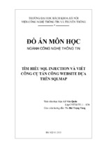
Access points can be placed within a building in an array that is either
linear or rectangular. An example of a linear array is shown in Fig. 6-2,
and an example of a rectangular array is shown in Fig. 6-3.1 Each of these
shows how APs can be located in a single-floor building or in a building
with only one floor needing WDLAN coverage. It is necessary only to
locate the APs in a way that provides coverage throughout the floor and
Chapter 6: Planning, Designing Data, Satellite Applications
167
Figure 6-2
A linear array of APs in
a single-floor building.
45°
R
D
R
R
also minimizes as far as possible the overlap between and among AP coverage areas. A linear array is used when the building is narrow relative to
R, and a rectangular array when the building width is large relative to R.
On the other hand, in a building that requires coverage on more than
one floor, adjacent floor coverage must be considered in locating each AP.
Usually, a staggered approach is used. As one moves along the length (or
width) of a building, one places APs first on one floor and then on an adjacent floor. In this case, the coverage of an AP’s adjacent floor coverage
168
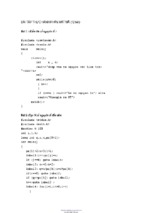
Figure 6-3
A rectangular array of
access points in a single-floor building.
Part 2:
Planning and Designing Data Applications
45°
R
D
must dovetail with the coverage of the next AP’s same floor coverage. As
in a single-floor building, a linear array is used when the building is
narrow relative to R, and a rectangular array when the building width
is large relative to R.
Let’s now illustrate by using four scenarios one will encounter when
planning and designing an indoor wireless data network. Each is determined by whether the building is single-story or multistory and by the
width of the building relative to R and R⬘. In each case, the appropriate
layout approach is given and the figure that illustrates it is listed. Solid
lines show coverage on a floor; dashed lines show adjacent floor coverage.
Scenario 1 A single-floor linear array is illustrated in Fig. 6-2.1 This is a
single-story building (or a building that requires wireless data coverage
on only one floor) whose width (smallest outer dimension) is not large
relative to R. D denotes the distance between adjacent APs.
Scenario 2 A single-floor rectangular array is illustrated in Fig. 6-3.
This is a single-story building (or a building that requires wireless data
coverage on only one floor) whose width (smallest outer dimension) is
large relative to R. D denotes the distance between adjacent APs.
Chapter 6: Planning, Designing Data, Satellite Applications
169
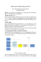
Scenario 3 A multifloor linear array is illustrated in Fig. 6-4.1 This is a
multistory building whose width (smallest outer dimension) is not large
relative to R and R⬘. D⬘ denotes the distance between adjacent APs on
different floors.
Scenario 4 A multifloor rectangular array is illustrated in Fig. 6-5.1 This
is a multistory building whose width (smallest outer dimension) is large
relative to R and R⬘. D denotes the distance between adjacent APs on the
same floor, and D⬘ denotes the distance between adjacent APs on different
floors.
Frequency Assignment
After the AP locations have been finalized and a coverage map has been
created, frequencies are assigned to the APs. In the United States and
Canada, three nonoverlapping channels (channels 1, 6, and 11) are used.
Thus, one can assign one of these three frequencies to each AP, doing so
Figure 6-4
A linear array of
access points in a
multifloor building.
R'
R
D'
R'
R
D'
R'
R
170
Part 2:
Figure 6-5
Rectangular array of
access points in a
multifloor building.
Planning and Designing Data Applications
D'
D
D'
in a way that minimizes cochannel overlap. Assignment of frequencies is
essentially a map coloring problem with three colors.
A variety of algorithms can be used to assign AP frequencies when the
AP coverages are known. One can do this exhaustively by checking the
cochannel overlap for all possible frequency assignments, and this is a reasonable approach if a computer is being used. Other, less time-consuming
algorithms are also possible, and some of these can give near-optimal
results. Another approach is to use the building coverage map that has
been created to visualize the coverage overlaps and assign frequencies so
that cochannel APs have only small coverage overlaps.
It is recommend that you assign AP frequencies in high-density areas
before low-density areas. If, for example, one uses three APs to cover a
high-density space, three different channels should be assigned to these
APs. These frequency assignments will subsequently need to be considered in assigning frequencies to nearby APs covering low-density areas.
This is true because APs covering the high-density space will usually
have some coverage overlap with APs covering only low-density areas.
Now, let’s look at how the planning and design of effective interworking between a multimedia terrestrial backbone and a satellite access
platform5 is a key issue for the development of a large-scale IP system
designed for transporting multimedia applications with QoS guarantees.
Chapter 6: Planning, Designing Data, Satellite Applications
171
This part of the chapter focuses on the planning and design of a gateway
station that acts as an interworking unit between the two segments of the
systems. The guarantee of differentiated QoS for applications within the
envisaged global IP system is achieved effectively by assuming that the IP
IntServ model in the satellite access system is combined with a DiffServ
fixed-core network, in which the RSVP aggregation protocol is implemented. Thus, the design activity of the IWU mainly focuses on the
following issues: seamless roaming between the two heterogeneous wireless data and wired environments, efficient integration between the two
IP service models (IntServ and DiffServ), and suitable mapping of terrestrial onto satellite bearer for traffic with different profiles and QoS
requirements.
Planning and Designing the
Interworking of Satellite IP-Based
Wireless Data Networks
Within the Internet community, strong expectations for a global system
that is able to offer a differentiated quality of service (QoS) come from
customers and applications. Such expectations both make the traditional
Internet model based on the “same service to all” concept inadequate and,
at the same time, move research and development activities toward the
deployment of large-scale IP networks (implementing the concept of
the global Internet).
Thus, on one hand, a commonly employed solution is to extend the
potentialities of the Internet through service differentiation mechanisms, in order that some groups of customers and applications can
obtain a superior level of service just by accepting different agreements
with the carrier and higher costs. Such an enormous interest in IP QoS
has brought about the rapid development of two standards for IP with
quality assurance: one, an integrated services model coupled to the
Resource Reservation Protocol (IntServ/RSVP), the other a differentiated services (DiffServ) model. On the other hand, it is clear that in order
to offer the negotiated service quality to mobile end users in an
enhanced broadband platform4 for the global Internet, the Internet with
QoS guarantees a new generation of multimedia satellite platforms that
must converge toward integrated platforms.
NOTE The research reported in this part of the chapter deals with the
issue of integrating IP with QoS assurance into a multimedia terrestrialsatellite infrastructure.
172
Part 2:
Planning and Designing Data Applications
The Internet Engineering Task Force (IETF) proposes access networks working with the IntServ/RSVP architecture and core networks
based on the DiffServ architecture. Such a proposal is driven by the
essential difference between IntServ and DiffServ models: While the former is interested in offering end-to-end QoS guarantees to a single flow,
the latter aims at scalability in large networks.
The envisaged solution guarantees many advantages. In particular, it
provides a scalable end-to-end service with reasonable QoS guarantees
across the core network, while an explicit reservation of resources is
available on the access links where the bandwidth may be scarce.
The difficulties and the consequent awkward research issues that lie
behind the deployment of effective interworking between the terrestrial
and satellite segments are mainly tied to the contrasting features of the
two cited IP models and the different natures of the environments
involved (one common feature: The satellite bandwidth is still a precious
resource, and the propagation delay strongly influences any design decisions). The proposed effective design of the whole terrestrial-satellite
multimedia system will focus on the following design options:
The design of a “reservation protocol” compatible with both
enhanced-IP models (DiffServ and IntServ) that is able to handle
heterogeneous connections with the required QoS on both the fixed
and satellite sides.
The implementation of a “mapping” among service classes of both
models to carry out effective IntServ-DiffServ integration.
The implementation of a mapping of fixed network bearer services
over the bearer services offered by the satellite access network in
order to perform effective integration of terrestrial and satellite
segments.2
It goes without saying that a gateway station, interconnecting satellite and terrestrial segments, has a role of prime importance within the
highlighted architecture. This makes its design particularly delicate.
The aim of this part of the chapter is therefore to address the research
issues pointed out hitherto and present a proposal for the design of the
interworking unit (IWU) operating within the terrestrial and satellite segments of an integrated system architecture for fourth-generation IP wireless data systems. The role of integrated QoS-aware IP models (DiffServ
and IntServ) within the designed infrastructure is also highlighted.
IP Networks with QoS Guarantee
The research IETF carried out on QoS provisioning in IP networks led to
the definition of two distinct architectures: integrated services (IntServ)
(with its signaling protocol RSVP) and differentiated services (DiffServ).
Chapter 6: Planning, Designing Data, Satellite Applications
173
The IntServ framework defines mechanisms that control the networklevel QoS of applications requiring more guarantees than those available when the traditional best-effort IP model is exploited. Provision of
end-to-end QoS control in the IntServ model is based on a per-flow
approach, in that every single flow is separately handled at each router
along the data transmission path.
The IntServ architecture assumes that explicit setup mechanisms are
employed to convey information to the routers involved in a source-todestination path. These mechanisms enable each flow to request a specific QoS level. RSVP is the most widely used setup mechanism.
Through RSVP signaling, network elements are notified of per-flow
resource requirements by using IntServ parameters. Subsequently, such
network elements apply admission control and traffic resource management policies to ensure that each admitted flow receives the requested
service. It is thus clear that RSVP implements its functionality by
means of signaling messages exchanged among sender, receiver, and
intermediate network elements. A sender host uses the Path message to
advertise the bandwidth requirements of its information flow downstream along the routing path. It also stores the path state in each node
along the way. By using the Resv message, the receiving host reserves
the amount of bandwidth necessary to guarantee a given QoS level. The
Resv message retraces exactly the path to the sender host, reserving the
resources in the intermediate routers (it creates and maintains reservation state in each node along the path used by the data) and is finally
delivered to the sender host, so that it can set up appropriate traffic control parameters. The following factors have prevented a large deployment of RSVP (and IntServ) in the Internet:
The use of per-flow state and per-flow processing raises scalability
problems for large networks.
Only a small number of hosts currently generate RSVP signaling.
Although this number is expected to grow dramatically, many
applications may never generate RSVP signaling.
The needed policy control mechanisms (access control,
authentication, and accounting) have become available only recently.2
In contrast to the per-flow orientation of RSVP, the DiffServ framework
defines mechanisms for differentiating traffic streams within a network
and providing different levels of delivery service to them. These mechanisms include differentiated per-hop queueing and forwarding behaviors
(PHBs), as well as traffic classification, metering, policing, and shaping
functions that are intended to be used at the edge of a DiffServ region.
The DiffServ framework manages traffic at the aggregate rather than
per-flow level. The internal routers in a DiffServ region do not distinguish
the individual flows. They handle packets according to their PHB identifier
174
Part 2:
Planning and Designing Data Applications
based on the DiffServ codepoint (DSCP) in the IP packet header. Since
DiffServ eliminates the need for per-flow state and per-flow processing, it
scales well to large networks.
IETF is currently interested in two types of DiffServ traffic classes:
uncontrolled and controlled. The first class offers qualitative service guarantees, but is unable to offer quantitative guarantees. An example of an
uncontrolled traffic class is the assured forwarding (AF) PBH. The controlled traffic class uses per-flow admission control to provide end-to-end
QoS guarantees. An example of controlled traffic class is represented by
the expedited forwarding (EF) PBH.
IntServ/RSVP and DiffServ can also be used as complementary technologies in the pursuit of end-to-end QoS. IntServ can be used in the
access network to request per-flow quantifiable resources along a whole
end-to-end data path, while DiffServ enables scalability across large networks and can be used in the core network. The main benefits of this
model are a scalable end-to-end IntServ framework with QoS guarantee in
the core network, and explicit reservations for the access network where
bandwidth can be a scarce resource.
Border routers between the IntServ and DiffServ regions may interact
with core routers using aggregate RSVP in the DiffServ region to reserve
resources between edges of the region. In fact, per-flow RSVP requests
from the IntServ region would be counted in an aggregate reservation.
The advantage of this approach is that it offers dynamic admission control
to the DiffServ network region, without requiring the level of RSVP signaling processing that would be required to support per-flow RSVP.
Details of this approach will be given later.
The Satellite-Terrestrial Integrated
Framework
Let’s now address the support of end-to-end IntServ over a DiffServ core
network. Figure 6-6 illustrates the whole reference architecture, whose
main components are a DiffServ network region and some IntServ network
regions.2
The DiffServ network region is a terrestrial core network that supports aggregate traffic control. This region provides two or more levels of
service based on the DSCP in packet headers. The IntServ network
regions are segments outside the DiffServ region that may consist of
generic IntServ access networks. In this case, let’s consider an IntServ
satellite access network on one side and any DiffServ terrestrial network on the other. The specific satellite network used here as a reference is the EuroSkyWay (ESW) geosatellite system (see Fig. 6-7), which
is an enhanced satellite platform for multimedia applications.2
- Xem thêm -