aDANANG UNIVERSITY
UNIVERSITY OF SCIENCE AND TECHNOLOGY
P.F.I.E.V
UNIVERSITY
GRADUATIONUNDERGRADUATE
THESIS
SubjectTitle:
DESIGN ROBOT CARTESIAN
COORDINATE ROBOT SYSTEM
AND MANUFACTURE A MODEL
Đã định dạng: Giãn cách dòng: Ké
Supervisor
:
MSc. Nguyen Đac Luc
Student
:
Tran Quoc Bao
Class
:
10CLC1
Major
:
Automation Production
Chapter I: Introduction
I.1 Arguments for choosing the subjectObjective
Technical sciences today are growing very strongly, led to great changes in
production. That is the change of productive forces in all sectors by replacing
human labor with machinery to ensure that labor productivity growth, yield and
product quality. Hence the use of the machine, also known as handusing
industrial robots in production are very popular because they meet the above
requirements. As we all know robots have many advantages, especially quality
Đã định dạng: Tiếng Anh (Mỹ)
and accuracy, in addition to mention the high economic efficiency, can work in
hazardous environments where people do not swear, the work requires careful
not to be confused, gentle subtle manipulations require a level of skilled workers,
and it is important not stress Robot as humans should be able to work all day.
The learning, researching Robot within the framework robot design
calculations will be the basis for us to calculate, design and control all types of
industrial robots for production. Specifically, here we chose a subjects in
calculatedion, designed of a robot that picks objects to serve arrangement,
moving industrial products.
I.2 Research Content
Analysis and choice select of design plans.
Set the kinetic equation for the system structure.
Design of mechanical components.
Design of controls.
Concludesion.
Chapter II: Analysis and select design plans
II.1 Some of the textures tTypical manipulators
a) Cartesian coordinates Robot type
Manipulator has 3 basic transmissions; translate according to the direction
of the coordinate system (configuration TTT),. Wworkspace work with is
rectangular blocks. Due to simple textures, this type of machine armmanipulator
has high rigidity, precision mechanics, so it's easy to ensure often used to
transport raw draftworkpices, assembly, welding plane …
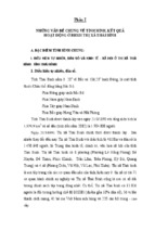
b) Cylindrical coordinates Robot type
Workspace of Robot has hollow cylindrical shape. Normally, the first joint
is rotation.. Example 3 degrees of freedom robot, has configure RTT
configurationas that is shown as following picture. There are cylindrical
coordinates type robots such as its robot Versatran robot of AMF (USA).
c) Spherical coordinates Robot type
Workspace of Robot has the globular shape. Normally, the stiffness of this
robot is lower than the above two types. Example 3 degrees of freedom robot
has, configuration RRR or RRT configuration.
d) Coordinates biomimicry Robot type
The first three movements are rotary motions;, The the first axis of rotation
is perpendicular to the other two axes. The other oriented movements are rotary
motion. Workspace of manipulators is almost identical a part of sphere.
e) SCARA Robot type
SCARA name stands for "Selective Compliant Articulated Robot Arm".
This robot type is used in assembly work so SCARA is sometimes been
interpreted as an acronym forcalled "Selective Compliance Assembly Robot
Arm". Three first joints of this type robot of configuration Robotare RRT, the
joint axes are vertical.
II.2 Analysis and choice machine texturesselect structure
a) Screw - Nut structure
Chú thích [B1]: Hiệu chỉnh ký hiệu tiế
Anh
Advantages:
Speed to move quickly by attaching coaxial.
Chú thích [B2]: Cần xem lại ưu điểm
này!
High accuracy.
The common plan in the currentPopular in industrial CNC
machines.
DefectDisavantages:
Translation of each sectional screw nut depends on steps of
screw thread so althought fast moving, accuracy is not high,
depends very much on the fitting and assembling,
construction products.
For more accurate replaceable screw actuator with ball screw.
Chú thích [B3]: Chỉ cần nói: cần lắp r
với độ chính xác cao
This transmission decreases friction between the nut and the screw,
advanced accuracy motion.
b) Tooth belt – Slider structure
Advantages:
Simple structure, low cost.
Work smoothly, without noise thanks to the flexibility of the belt,
suitable for high-speed transmission.
Transmission between widely separated axes.
High performance transmission.
Convenient, easy to control.
Defect:
There may be problems with size, great framework.
The force exerted on the drive shaft is large and must tighten the belt
initial at fisrt.
The lifespan of the belt is usually lower.
Requires high precision, the construction and assembly meet more
dificult.
The cost of making relatively high.
Difficulty in adjusting of the belt parallel to drag the axes the most
accurate.
c) Pneumatic Cylinder.
Advantages:
Abundant energy source.
Used for many different purposes such as cleaning work,
transmission in the machine …
Ability to transmit away by pipeline systems with small losses;
Pneumatic can drain out without causing harm to the environment.
High-speed transmission, flexible;
Easy to control with the reliability and high accuracy.
Defect:
Power transmission is not large.
The accuracy is not high.
Pneumatic line is released into the environment can cause noise.
d) Structure of navigation.
Request:
The surface of the slider requires high corrosion resistance,
0,004÷0,008 (mm/year).
Request about the hardness of the slider relatively important.
Slider of the camera body, office machines, ironing machine should
be fine processed by grinding or scraping method by means of
polishing, grinding.
Flatness allows the slider 0.02 ÷ 0.03 mm / m.
Glossy of surface from level 6 to level 8.
The openings of the slider and the more fitting for it to be checked
by painting and by 0.04 mm thick gauge.
The guide slider: rectangular slider, swallow tail slider,
roller slider cylindrical, V slider, cylinder slider.
The transmission used
To save in economic terms, while ensuring the requirements of the
problem posed, we choose design Robot 3 degrees of freedom TTT, Robot has 3
translational links locate a point on the space in coordinates descarde, and a hand
grip for gripping objects. Based on the analysis of transmission alternatives
above, combined with the ability to calculate the supply and purchase of the
necessary components and economic conditions, plans for tooth belt - slider
transmission and pneumatic cylinders are selected to perform robot arm.
Chapter III: Set the kinetic equation
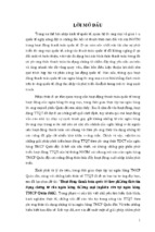
III.1 Attach the coordinates to the links
III.2 Parameters tabulated DH
Link
θi
αi
di
ai
1
0
90
d1
a1
Đã định dạng: Giãn cách dòng: Ké
2
-90
90
d2
a2
Đã định dạng: Giãn cách dòng: Ké
3
0
0
d3
a3
Đã định dạng: Giãn cách dòng: Ké
Đã định dạng: Giãn cách dòng: Ké
III.3 Dynamical equations
0
0
T3
1
0
0
1
1
0
0
0
0
0
a1 d3
d 2
d1 a2 a3
1
Chapter IV: Design of mechanical components
IV.1 Choose axis guide
We choose slided circular axis SDK Crom-plated with Ф8, hardness
58HRC.
IV.2 Calculate and choose motor
IV.2.1 Link 1
Total mass of belt and load m1 = 5 [kg]
Roller diameter D = 20 [mm]
Roller mass m2 = 0,1 [kg]
Friction coefficient of sliding surface µ = 0.04
Belt and roller efficiency η = 0,9
Frequency of power supply 60 Hz (Motor speed: 72 r / min).
Belt speed
v
.D.N
60
.2.72
60
7,5 mm/s
Calculate the Required Torque
TL
F .D m1.g..D
2,18.103 N.m
2.
2.
Load inertia of belt and load
2
.2.103
.D
2
6
J m1 m1.
5.10 kg.m
5.
2.
2.
2
Load Inertia of Roller
1
1
2
J m 2 .m2 .D 2 .0,1.(2.103 ) 2 0, 05.106 kg.m
8
8
The load inertia is calculated as follows:
J L J m1 2.J m2 5,1.106 kg.m
2
Calculate the Acceleration Torque
Ta ( J 0 J L )
. s
180.n
f 2 905.J 0 4, 6.103 N.m
Here θs = 1,8o, f = 60Hz, n = 3,6o / θs
Jo : Rotor Inertia
Required Torque
TM (TL Ta ) 2 1810.J 0 13,56.103 N.m
Choose a Motor
Select a motor that satisfies both the required torque and the
permissible load inertia.
Motor
Rotor Inertia
Permissible
Load Output Torque
Inertia [kg·m2]
[kg·m2]
57BYGH2500B
[N·m]
1.4x10⁻⁴
7x10⁻⁴
1,00
When the required torque is calculated by substituting the rotor inertia, TM
is obtained as 0,267 Nm, which is below the output torque. Next, check the
permissible load inertia. Since the load inertia calculated in above is also
below the permissible load inertia, 57BYGH2500B can be used in this
application.
IV.2.2 Link 2
Total mass of belt and load m1 = 2 [kg].
Roller diameter D = 20 [mm].
Roller mass m2 = 0,1 [kg].
Friction coefficient of sliding surface µ = 0,04.
Belt and roller efficiency η = 0,9.
Frequency of power supply 60 Hz (Motor speed: 72 r / min).
Belt speed
v
.D.N
60
.2.72
60
7,5 mm/s
Calculate the Required Torque
TL
F .D m1.g..D
0.87.103 N.m
2.
2.
Load inertia of belt and load
Đã định dạng: Giãn cách dòng: Ké
Đã định dạng: Giãn cách dòng: Ké
2
.2.103
.D
2
6
J m1 m1.
2.
2.10 kg.m
2.
2.
2
Load Inertia of Roller
1
1
2
J m 2 .m2 .D 2 .0,1.(2.103 ) 2 0, 05.106 kg.m
8
8
The load inertia is calculated as follows
J L J m1 2.J m2 2,1.106 kg.m
2
Calculate the Acceleration Torque
Ta ( J 0 J L )
. s
f 2 905.J 0 1,9.103 N.m
180.n
Here θs = 7,2o, f = 60Hz, n = 3,6o / θs
Jo : Rotor Inertia
Required Torque
TM (TL Ta ) 2 1810.J 0 2,77.103 N.m
Choose a Motor
Select a motor that satisfies both the required torque and the
permissible load inertia.
Motor
Rotor Inertia
[kg·m2]
Permissible
Load Output Torque
Inertia [kg·m2]
[N·m]
YH42BYGH47
1.4x10⁻⁴
7x10⁻⁴
0.55
When the required torque is calculated by substituting the rotor inertia, TM
is obtained as 0,256 Nm, which is below the output torque. Next, check the
permissible load inertia. Since the load inertia calculated in above is also below
the permissible load inertia, YH42BYGH47 can be used in this application.
IV.2.3 Link 3
Conditions for the piston can lift objects as:
FP >= Mob =10N
Then FP = p.S
I choose pressure air compressor: p = 6bar = 6.105N/m2
Here : S
And S
FP
10
1, 67.105 m2
p 6.105
.d 2
4
d
4.S
4,6.10-3 m =4,6 mm
We choose 2 axial plunger d=5(mm), Cruise 20mm
IV.2.4 Hand grip
The weight will be required to pick up: 10N.
Size : long : L=15mm=0,015m.
broad: a=25mm=0,025m.
tall :b=10mm=0,01 m.
Frictional force acting on the object is:
Fms = k.FP, we choose sliding friction coefficient k = 0,3
Đã định dạng: Giãn cách dòng: Ké
Đã định dạng: Giãn cách dòng: Ké
Conditions for the piston do not drop object is:
Fms >= Mob =10N hay k.FP>=10
Mà FP = p.S
I choose pressure air compressor p = 6bar = 6.105N/m2.
Here : S
And S
k.FP 0,3.10
0,5.105 m2.
p
6.105
.d 2
4
d
4.S
4,5.10-3 m =2,5 mm.
We choose plunger d= 4mm. Cruise 20mm
Chapter V: Design of controls
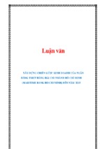
V.1 Construction algorithm flowchart
V.2 The device and control program
Solenoid valve 5/2
When electric signal doesn’t impact entrance (0), the gate (3) is blocked,
gate (1) connected to the gate (2) and gate (4) connected to the gate (5). When
there is the electrical signal that impacts at the door (0), the barrel valve will shift
to the right, the gate (2) connected to the gate (3) and gate (1) connected to the
gate (4) while the door (5) is blocked. When the impact signal at the door (0) is
lost, under the action of the barrel valve springs return the original location.
PIC16F887
PIC is a microcontroller RISC architecture, running a command a machine
cycle (4 oscillator cycles).
PIC16F887 they have 40 legs, each leg has a different function. Including
some multiple-use leg (compound), each leg can act as a way to export / import
(I / O) independently or as a special function used to communicate with
peripheral devices.
- Xem thêm -